EP0911223B1 - Occupant restraint system having serially connected devices - Google Patents
Occupant restraint system having serially connected devices Download PDFInfo
- Publication number
- EP0911223B1 EP0911223B1 EP98119493A EP98119493A EP0911223B1 EP 0911223 B1 EP0911223 B1 EP 0911223B1 EP 98119493 A EP98119493 A EP 98119493A EP 98119493 A EP98119493 A EP 98119493A EP 0911223 B1 EP0911223 B1 EP 0911223B1
- Authority
- EP
- European Patent Office
- Prior art keywords
- restraint system
- devices
- central control
- system device
- communication
- Prior art date
- Legal status (The legal status is an assumption and is not a legal conclusion. Google has not performed a legal analysis and makes no representation as to the accuracy of the status listed.)
- Expired - Lifetime
Links
- 238000004891 communication Methods 0.000 claims description 62
- 238000000034 method Methods 0.000 claims description 9
- 230000001105 regulatory effect Effects 0.000 claims description 5
- 230000000452 restraining effect Effects 0.000 claims description 5
- 230000001276 controlling effect Effects 0.000 claims description 4
- 230000004044 response Effects 0.000 claims description 4
- 239000012530 fluid Substances 0.000 description 6
- 230000006870 function Effects 0.000 description 5
- 238000002604 ultrasonography Methods 0.000 description 3
- 230000001133 acceleration Effects 0.000 description 2
- 238000013461 design Methods 0.000 description 2
- 210000003127 knee Anatomy 0.000 description 2
- 238000012986 modification Methods 0.000 description 2
- 230000004048 modification Effects 0.000 description 2
- 230000008569 process Effects 0.000 description 2
- 230000001953 sensory effect Effects 0.000 description 2
- 239000000758 substrate Substances 0.000 description 2
- 238000011144 upstream manufacturing Methods 0.000 description 2
- IJGRMHOSHXDMSA-UHFFFAOYSA-N Atomic nitrogen Chemical compound N#N IJGRMHOSHXDMSA-UHFFFAOYSA-N 0.000 description 1
- 238000013459 approach Methods 0.000 description 1
- 238000010586 diagram Methods 0.000 description 1
- 229910001873 dinitrogen Inorganic materials 0.000 description 1
- 230000000694 effects Effects 0.000 description 1
- 239000003999 initiator Substances 0.000 description 1
- 239000000463 material Substances 0.000 description 1
- 229910052757 nitrogen Inorganic materials 0.000 description 1
Images


Classifications
-
- B—PERFORMING OPERATIONS; TRANSPORTING
- B60—VEHICLES IN GENERAL
- B60R—VEHICLES, VEHICLE FITTINGS, OR VEHICLE PARTS, NOT OTHERWISE PROVIDED FOR
- B60R21/00—Arrangements or fittings on vehicles for protecting or preventing injuries to occupants or pedestrians in case of accidents or other traffic risks
- B60R21/01—Electrical circuits for triggering passive safety arrangements, e.g. airbags, safety belt tighteners, in case of vehicle accidents or impending vehicle accidents
-
- B—PERFORMING OPERATIONS; TRANSPORTING
- B60—VEHICLES IN GENERAL
- B60R—VEHICLES, VEHICLE FITTINGS, OR VEHICLE PARTS, NOT OTHERWISE PROVIDED FOR
- B60R21/00—Arrangements or fittings on vehicles for protecting or preventing injuries to occupants or pedestrians in case of accidents or other traffic risks
- B60R21/01—Electrical circuits for triggering passive safety arrangements, e.g. airbags, safety belt tighteners, in case of vehicle accidents or impending vehicle accidents
- B60R21/015—Electrical circuits for triggering passive safety arrangements, e.g. airbags, safety belt tighteners, in case of vehicle accidents or impending vehicle accidents including means for detecting the presence or position of passengers, passenger seats or child seats, and the related safety parameters therefor, e.g. speed or timing of airbag inflation in relation to occupant position or seat belt use
- B60R21/01512—Passenger detection systems
-
- B—PERFORMING OPERATIONS; TRANSPORTING
- B60—VEHICLES IN GENERAL
- B60R—VEHICLES, VEHICLE FITTINGS, OR VEHICLE PARTS, NOT OTHERWISE PROVIDED FOR
- B60R21/00—Arrangements or fittings on vehicles for protecting or preventing injuries to occupants or pedestrians in case of accidents or other traffic risks
- B60R21/01—Electrical circuits for triggering passive safety arrangements, e.g. airbags, safety belt tighteners, in case of vehicle accidents or impending vehicle accidents
- B60R2021/0104—Communication circuits for data transmission
- B60R2021/01047—Architecture
- B60R2021/01054—Bus
- B60R2021/01068—Bus between different sensors and airbag control unit
-
- B—PERFORMING OPERATIONS; TRANSPORTING
- B60—VEHICLES IN GENERAL
- B60R—VEHICLES, VEHICLE FITTINGS, OR VEHICLE PARTS, NOT OTHERWISE PROVIDED FOR
- B60R21/00—Arrangements or fittings on vehicles for protecting or preventing injuries to occupants or pedestrians in case of accidents or other traffic risks
- B60R21/01—Electrical circuits for triggering passive safety arrangements, e.g. airbags, safety belt tighteners, in case of vehicle accidents or impending vehicle accidents
- B60R2021/0104—Communication circuits for data transmission
- B60R2021/01047—Architecture
- B60R2021/01054—Bus
- B60R2021/01075—Bus between the airbag control unit and pyrotechnic fuses or equivalent actuators
Definitions
- the present invention is generally directed to an occupant restraint system, having a central controller that communicates with a plurality of restraint system devices, and associated methods of providing and using the restraint system.
- the present invention is particularly directed to a system in which the restraint system devices are connected in a daisy chain arrangement.
- An occupant restraint system includes one or more sensor devices for sensing vehicle characteristics and/or occupant characteristics. The sensed characteristics are used to determine whether a vehicle occupant is to be restrained and/or a deployment profile for restraining the occupant. Examples of such sensor devices include a vehicle acceleration sensor, an occupant position sensor, and an occupant weight sensor.
- the restraint system also includes one or more actuatable restraint devices for restraining the occupant. Examples of such restraint devices include an air bag module, a knee bolster, and a seat belt pretensioner.
- US 5,404,460 A discloses an electronic system having multiple identical Input/Output (I/O) devices which are all connected in daisy-chain fashion on a serial bus.
- I/O Input/Output
- the I/O device at the end of the chain configures itself as Device 0, and outputs data to the next device which configures it as Device 1.
- Device 1 then outputs data to the next device which configures it as Device 2, and so on until all the l/0 devices have been assigned a device number.
- the I/O devices are configured to unique addresses without additional external pins or intervention by the System Controller, minimizing package size and eliminating logic which would otherwise be required if the System Controller had to configure these I/O devices.
- the present invention provides an occupant restraint system for a vehicle.
- a plurality of controllable restraint system devices is provided within the restraint system.
- Each of the restraint system devices has programmable means, which is programmable, for permitting control of the respective restraint system device.
- Central control means of the system provides programming signals and control signals for the restraint system devices.
- a connection line connects the central control means and the restraint system devices. The connection line is for communication between the central control means and the restraint system devices.
- the system includes a plurality of communication regulation means.
- the communication regulation means are connected in series along the connection line.
- Each of the communication regulation means is associated with one of the restraint system devices.
- Each of the communication regulation means regulates communication between the central control means and any restraint system device(s) downstream of the associated restraint system device along the connection line from the central control means.
- the system includes a plurality of enable means.
- Each of the enable means is associated with one of the restraint system devices.
- Each enable means causes the communication regulation means associated with the one restraint system device to permit communication between the central control means and the any restraint system device(s) downstream of the one restraint system device. The permission of communication is in response to the central control means providing a programming signal to the one restraint system device, via the connection line.
- the present invention includes a method of configuring and controlling an occupant restraint system for a vehicle.
- the system has a plurality of controllable restraint system devices.
- Each of the restraint system devices has a programmable means for permitting control of the respective restraint system device.
- the system includes central control means, which provides programming signals and control signals for the restraint system devices.
- the system includes a connection line connecting the central control means and the restraint system devices.
- a plurality of communication regulation means is connected in series along the connection line.
- Each of the communication regulation means is associated with a respective restraint system device.
- Communication is regulated at one of the communication regulation means.
- the regulated communication is between the central control means and any restraint system device(s) downstream of the restraint system device associated with the one communication regulation means along the connection line from the central control means.
- the regulation is such that the communication between the central controller and the any restraint system device(s) downstream of the associated restraint system device is permitted after the central control means provides a programming signal to the one restraint system device, via the connection line.
- a representation of the present invention is schematically shown in Fig. 1 as an occupant restraint system 10.
- the system 10 includes a plurality of restraint system devices 12.
- the restraint system devices 12 may be comprised of any combination of devices.
- some of the restraint system devices 12 may be actuatable occupant restraint devices (e.g., devices 1 and 2 of Fig. 1) for restraining a vehicle occupant.
- occupant restraint devices include an air bag device, a knee bolster, a seat belt lock, a seat belt pretensioner, and a D-ring adjuster.
- the example shown in Fig. 1 has occupant restraint devices 12A and 12B, which are air bag restraint devices.
- Each restraint device 12A and 12B includes an associated inflatable restraint 14, commonly referred to as an air bag.
- the air bag 14 is stored in a folded condition within the device 12 in a manner well known in the art.
- a source 16 of inflation fluid e.g., nitrogen gas
- the source 16 of inflation fluid is commonly referred to as an inflator, and includes a stored quantity of pressurized inflation fluid and/or an inflation fluid generating material.
- the inflator 16 has an associated initiator (e.g., a pyrotechnic squib), which is electrically activated to initiate flow of the inflation fluid from the inflator.
- the flow of inflation fluid to the air bag 14 inflates the air bag, as will be appreciated by a person of ordinary skill in the art.
- the example of Fig. I contains two restraint system devices 12(N-1) and 12N that are sensor devices.
- Each sensor device senses a characteristic that is used to determine whether a vehicle occupant is to be restrained and/or deployment profile for restraining the occupant.
- sensor devices include a vehicle crash sensor, such as an accelerometer, an occupant position sensor, such as an ultrasound and infrared sensor, and an occupant weight sensor, such as a pressure sensor.
- the sensor device 12(N-1) of Fig. 1 is an occupant characteristic sensor (e.g., an ultrasound sensor) with an occupant characteristic sensor function 15
- the sensor device 12N of Fig. 1 is a vehicle characteristic sensor (e.g., an accelerometer) with a vehicle characteristic sensor function 17.
- restraint system devices for discussions which are applicable to any or all of the devices in the restraint system 10.
- restraint system devices 12A-12N of the illustrated example have elements which are identified by numbers with corresponding alphabetic suffixes.
- alphabetic suffixes are sometimes omitted for generic discussions, i.e., applicable to all of the restraint system devices.
- a first occupant restraint device 12A is a vehicle side-impact air bag restraint device mounted in a driver's side door 24.
- the air bag 14A Upon inflation of the air bag 14A of the driver's side door mounted restraint device 12A, the air bag 14A extends at a side of a driver's seat 26 of the vehicle.
- a second one of the devices is a hub-mounted restraint device 12B located within a hub of the vehicle's steering wheel 28.
- the air bag 14B of the hub-mounted restraint device 12B Upon inflation of the air bag 14B of the hub-mounted restraint device 12B, the air bag 14B inflates at a location in front of the driver's seat 26, with respect to the fore-to-aft axis of the vehicle 22.
- a third one of the restraint devices (i.e., 12C) is mounted in a passenger side of an instrument panel 30 of the vehicle 22.
- the air bag 14C of the instrument panel-mounted restraint device 12C inflates at a location in front of a front passenger seat 32 of the vehicle 22.
- a fourth one of the restraint devices is a door mounted restraint device 12D located in a passenger door 34 of the vehicle 22.
- the air bag 14D of the door-mounted restraint device 12D inflates at a location to the side of the passenger seat 32.
- a first one 12E of the two sensor devices is an ultrasound sensor (e.g., an ultrasonic transducer 20 and associated drive/monitor circuitry) for sensing the presence and position of a front seat passenger.
- the second sensor device 12F is an accelerometer for sensing vehicle acceleration in the fore-to-aft direction. It will be appreciated that additional and/or different actuatable occupant restraint devices and that additional and/or different sensor devices can be included within the restraint system 10.
- each restraint system device 12 includes control circuitry 18, which controls the respective device.
- the control circuitry controls actuation of the inflator 16.
- the control circuitry 18 contains logic and memory circuitry, and is addressable/programmable.
- the control circuitry 18 is connected to communicate in a network within the restraint system 10. The addressable aspect of the control circuitry 18 is provided such that the restraint system device 12 "knows" when a communication is directed to that particular device.
- the restraint system 10 includes a central controller 38 (Fig. 1).
- the central controller 38 includes a microcomputer.
- the central controller 38 receives sensory input from the sensor devices (e.g., 12(N-1) 12N), and using the sensory input regarding the sensed characteristics, makes determination regarding restraint module control (e.g., the central controller operates a crash algorithm).
- the restraint devices e.g., 12A, 12B
- the restraint devices could have adjustable aspects that are adjustable to tailor deployment of the respective restraint device. Information derived from such sensed characteristic(s) would be used by the controller 38 to determine adjustment of the deployment variable(s).
- Such adjustable deployment variables include timing, air bag dynamic profile, pressure, etc.
- the controller 38 would control the adjustment of the deployment variable(s) accordingly.
- the central controller 38 analyzes the information derived from the sensed characteristics and determines if a deployment crash condition is occurring.
- a deployment crash condition is one in which deployment of one or more air bag(s) 14 is desired to hopefully, in combination with the vehicle seat belts (not shown) or other actuatable restraints, enhance the restraint function of the occupant restraint system 10. Also, any adjustment of the deployment profiles is accomplished.
- the restraint system 10 is configured such that the central controller 38 appropriately actuates the plurality of restraint system devices 12.
- the central controller 38 is connected to the plurality of restraint system devices 12 via a control interconnection 44.
- the control interconnection 44 between the central controller 38 and the restraint system devices 12, has at least one connection that is a serial or "daisy-chain" connection along the restraint system devices.
- two connection lines 46A, 46B (Fig. 1) provide the control interconnection 44 between the central controller 38 and the restraint system devices 12.
- the central controller 38 includes a communication portion 48 connected to the two connection lines 46A, 46B.
- the communication portion 48 outputs communication signals, from the central controller 38 to the restraint system devices 12, via the connection lines 46A, 46B.
- the communication portion 48 also receives communication signals from the restraint system devices 12, via the connection lines 46A, 46B.
- the central controller 38 is connected to both the vehicle power source 50 (i.e., the vehicle battery) and to vehicle ground 52.
- the central controller 38 via the communication portion 48, also provides electrical power for the plurality of restraint system devices 12, via the connection lines 46A, 46B.
- Any known method of providing electrical power and communication signals over the same electrical interconnection(s), can be employed within the system. Thus, the known methods of electrical power and communication signal provision are not discussed in detail herein.
- connection lines 46A and 46B of the control interconnection 44 one of the connection lines connects the central controller 38 to each of the restraint system devices 12 in parallel.
- the parallel-connection is provided by the line 46B.
- the other connection line 46A connects the central controller 38 to the restraint system devices 12 in series (i.e., the daisy chain connection).
- the connection lines 46A, 46B are connected to the control circuitry 18 of the respective device.
- the central controller 38 can communication with, and can supply power to, the control circuitry 18 of the respective device 12.
- each restraint system device 12 Associated with each restraint system device 12 is an electronic switch 54.
- Each electronic switch 54 has an “ON” or “closed” state, and an “OFF” or “open” state. In its “ON” state, each switch 54 permits electrical signals to flow through the switch, and in the "OFF” state, the switch blocks/interrupts flow of the electrical signals.
- the electronic switch 54 for each restraint system device 12 is shown within the respective device.
- the electronic switch 54 can be a separate element from the respective restraint system device 12, and yet be associated with the restraint system device.
- the electronic switches 54 are connected in series, along one of the connection lines 46A, 46B. In Fig. 1, the switches 54 are in series along the connection line 46A.
- the electronic switch 54 associated with a particular restraint system device 12 is interposed between the central controller 38 and all of the restraint system devices 12, if any, which are "downstream" of the particular restraint system device.
- the restraint system devices 12 are, therefore electrically "daisy-chained". It should be noted that although, the illustrated examples have their sensor devices located at a "far" end of the daisy-chain from the controller 38, other connection orders are possible.
- Each of the electronic switches 54 is in its "OFF" state until its associated restraint system device 12 is programmed.
- Programming of each of the restraint system devices 12 includes establishing an unique address for each device 12. Programming may also include initialization of the restraint system device 12 (e.g., setting of initial states within the restraint system device).
- Programming by the central controller 38 allows the programmed restraint system device 12 to engage in operational communication with the central controller.
- the inflator 16 is controllable either by the controller 38, or by its associated control circuit 18 in response to data received from controller 38.
- Initial assembly of the system 10 shown in Figure 1 requires an initial programming of addresses for the restraint system devices 12. Also whenever a module is replaced, the new module must be programmed with the address of the module that it replaced. The establishment of these module addresses is referred to as a programming sequence. Once programmed by the central controller 38 during the programming sequence, the control circuitry 18 of the respective device 12 causes its associated electronic switch 54 to "close” (i.e., turn "ON").
- the restraint system 10 of the present invention permits the restraint system devices 12 to be quickly and easily assembled into the system, and permits quick and easy removal and replacement of the restraint system devices (e.g., replacement of a restraint device after deployment). Further, communication between the central controller 38 and the restraint system devices 12 is readily established both initially or when a particular restraint system device 12 is replaced. For example, assume for the purpose of illustration, that the restraint system 10 is newly assembled, or that at least one of the restraint system devices 12 is being replaced. All of the electronic switches 54 either are set or are reset to an initial "open" state or condition by any suitable means for accomplishing the task (e.g., a default or reset command).
- the central controller 38 outputs a polling signal on the control interconnection 44 (e.g., a coded signal on connection line 46A). Because all of the electronic switches 54 are in an "open" state, only the first restraint system device 12A (i.e., device 1 of Fig. 1) receives the polling signal. The first restraint system device 12A (device 1) replies to the central controller 38, and, through a sequence of communications between the central controller and the first restraint system device, the first restraint system device is programmed.
- a polling signal on the control interconnection 44 e.g., a coded signal on connection line 46A.
- the control circuitry 18 "closes" the electronic switch 54A associated with the first restraint system device 12A.
- the central controller 38 again outputs a polling signal on the control interconnection 44 (e.g., a signal on line 46A).
- the first restraint system device 12A which is now programmed, does not respond to the present polling signal.
- the second restraint system device 12B i.e., device 2 of Fig. 1 receives the polling signal.
- the currently un-programmed second restraint system device 12B responds to the central controller 38 and, via a sequence of communication between the controller 38 and the second restraint system device 12B, the central controller 38 programs the second restraint system device.
- the second to last restraint system device 12(N-1) i.e., device (N-1) of Fig. 1) is programmed (i.e., an address established) and causes its associated electronic switch 54(N-1) to "close” such that the last restraint system device 12N (i.e., device N of Fig. 1) may subsequently be programmed (i.e., an address established).
- the electronic switch 54N of the last restraint system device may be "closed”. However, closing this switch 54N has no consequence.
- connection lines 46A, 46B are shown as having free ends which are connectable to an added device.
- the free ends of the connection lines 46A, 46B may be plug-in ports for wires extending from an added device.
- all of the restraint system devices 12 may communicate with the central controller 38. Communication may be by single bit signals, or by a multi-bit series of signals. The communication between the central controller 38 and the restraint system devices 12 may be governed by any suitable communication scheme. For example, in order to avoid signal "collisions" on the control interconnection 44, a communication protocol may be imposed such that each restraint system device 12 may only communicate at its assigned time.
- the central controller 38 may provide a communication signal intended for any one, any combination, or all of the restraint system devices 12.
- An example of a signal provided to some of the restraint system devices 12 is an "actuate" signal provided to the steering wheel hub-mounted and the instrument panel-mounted restraint system devices 12B and 12C (Fig. 2) when the central controller 38 determines that the vehicle 22 is involved in a head-on collision.
- the devices 12A and 12B may be any type of restraint system device (e.g., a sensor device or a restraint device).
- the connection line 46B is the communication drive line and the connection line 46A is the return line.
- the connection line 46B connects the central controller 38 to each of the control circuits 18 of the restraint system devices 12 (i.e., the parallel connection).
- the connection line 46A is daisy-chained between the plurality of restraint system devices 12 (i.e., the series connection).
- the connection line 46B is connected to an input port 60 of the restraint system device.
- the connection line 46A is connected to a return port 62 of the restraint system device 12.
- the electronic switch 54 includes an N-channel MOSFET 64. Focusing on the first restraint system device 12A, the source 66A and substrate 68A of the N-channel MOSFET 64A are connected together and are connected to the return port 62A of the device 12A. The drain 70A of the N-channel MOSFET 64A is connected to a daisy chain port 72A of the restraint system device 12A. A segment of the connection line 46A extends from the daisy chain port 72A of the restraint system device 12A to the return port 62B of the next, downstream restraint system device 12B (i.e., in the direction away from the central controller 38).
- the gate 74A of the N-channel MOSFET 64A is connected to a control node 76A, which is connected, in turn to the control circuitry 18A of the restraint system device 12A.
- a resistor 78A couples the control node 76A to the input port 60A.
- a zener diode 80A is operative between the control node 76A and the return port 62A. The zener diode 80A protects the N-channel MOSFET 64A from damage when the voltage at input port 60A relative to return port 62A exceeds the maximum gate to source voltage of the MOSFET.
- the control circuitry 18A is connected to the input port 60A and the return port 62A.
- the second restraint system device 12B has the same structure identified by a suffix "B".
- the control circuitry 18A After the central controller 38 has finished programming (i.e., establishing an address) the restraint system device 12A, the control circuitry 18A "closes” the electronic switch 54A by controlling the control node 76A (i.e., the gate 74A of the N-channel MOSFET 64). Specifically, prior to the restraint system device 12A being programmed, the control circuitry 18A biases the MOSFET 64 "OFF". When the MOSFET 64 is "OFF", the return port 62A of the restraint system device 12A is not connected to the daisy chain port 72A of the restraint system device 12A. Once the restraint system device 12A is programmed, the control circuitry 18A biases the MOSFET 64A "ON".
- This daisy chain process of programming the respective devices 12 continues until all have been programmed (i.e., given associated addresses). Assume that within the system 10, a restraint system device 12X was to be replaced. Restraint system device 12X can be any one of the devices 12A-12N. Once placed in the daisy chain, the MOSFET 64X of the device 12X would be biased “OFF” since the control circuit 18X of device 12X has not yet been programmed. This would "break” the daisy chain connection, and all, if any, devices downstream of device 12X would be non-responsive to the central controller 38 since their control circuits 18 would lose their ground connection.
- controller 38 can detect such occurrence and proceed to send the appropriate signal(s) to program the controller 18X. It should be appreciated that once device 12X is connected in the system 10, its associated control circuit 18X is grounded through the device 18(X-1), if any. Once device 18X is programmed, the control circuit 18X would bias its associated MOSFET 64X "ON" to complete the serially connected daisy chain.
- Fig. 4 illustrates another embodiment of the present invention using a P-channel MOSFET as the switch 54'.
- a prime i.e., " ' ”
- the prime designates that the identified element of this embodiment has a function similar to its earlier mentioned counterpart, but has a different structure.
- the use of alphabetic suffixes is the same as its use above.
- connection line 46A' (Fig. 4) is connected to the central controller 38' as the driven connection line and the connection line 46B' is connected to the controller as the return line.
- the connection line 46A' is daisy-chained among the plurality of restraint system devices 12' and the connection line 46B' is connected to the plurality of restraint system devices in a parallel connection arrangement.
- a P-channel MOSFET 84 is provided within the electronic switch 54' at each restraint system device 12'.
- the source 86 and substrate 88 of the P-channel MOSFET 84 are connected together and are connected to an input port 90 of the restraint system device 12'.
- the input port 90A is connected to the line 46A' from the central controller 38.
- the drain 92A of the P-channel MOSFET 84A is connected to a daisy chain port 94A.
- the daisy chain port 94A of the first restraint system device 12A' (device 1) is connected to the input port 90B of the second restraint system device 12B' (device 2). Accordingly, the daisy chain along the connection line 46A' is through the P-channel MOSFETs 84.
- the gate 96A of the P-channel MOSFET 84A is connected to a gate node 98A.
- Zener diode 100A is operatively connected between the input port 90A and the gate node 98A.
- the gate node 98A is connected to a return port 102A, via a resistor 104A.
- the gate node 98A is also connected to a collector 106A of a PNP transistor 108A.
- the emitter 110A of the PNP transistor 108A is connected to the input port 90A, and the base 112A of the PNP transistor is connected to a control node 114A.
- the control node 114A is connected to the control circuitry 18A' and is also connected to the input port 90A, through a resistor 116A. Accordingly, the resistor 116A is connected between the emitter 110A and base 112A of the PNP transistor 108A. Further, the control node 114A serves as both the control node for the electronic switch 54A' and the input node for the control circuitry 18A'.
- the second restraint system device 12B' has the same structure identified by a suffix "B".
- the control circuitry 18' biases the control node 114 so as to, in turn, bias the P-channel MOSFET 84 "OFF". Once the restraint system device 12' is programmed, the control circuitry 18' biases the control node 114 so as to maintain the P-channel MOSFET 84 "ON". Thus, the input port 90 is connected to the daisy chain port 94. The input port 90 of the next restraint system device is, thus, connected to the central controller 38 through the upstream P-channel MOSFET 84. Programming of all devices 12' is completed initially through the series daisy chain. A replacement devices 12X' would initially break the daisy chain until it is programmed with an address which, in turn, results in its associated switch 54' to close.
Landscapes
- Engineering & Computer Science (AREA)
- Mechanical Engineering (AREA)
- Air Bags (AREA)
Description
- The present invention is generally directed to an occupant restraint system, having a central controller that communicates with a plurality of restraint system devices, and associated methods of providing and using the restraint system. The present invention is particularly directed to a system in which the restraint system devices are connected in a daisy chain arrangement.
- An occupant restraint system includes one or more sensor devices for sensing vehicle characteristics and/or occupant characteristics. The sensed characteristics are used to determine whether a vehicle occupant is to be restrained and/or a deployment profile for restraining the occupant. Examples of such sensor devices include a vehicle acceleration sensor, an occupant position sensor, and an occupant weight sensor. The restraint system also includes one or more actuatable restraint devices for restraining the occupant. Examples of such restraint devices include an air bag module, a knee bolster, and a seat belt pretensioner.
- As the sophistication of occupant restraint systems has increased, the number and complexity of the sensor and restraint devices in a single vehicle has increased. In response to the increased number and complexity of devices, there has been a movement toward centralized control of the devices to reduce cost and to increase reliability of the overall restraint system.
- Also, sometimes there is a need to replace one of the restraint system devices. For example, after deployment of an individual restraint device, the deployed restraint device must be replaced. Also, if a sensor device becomes inoperative, it must be replaced. The replacement device must be properly connected into the overall restraint system.
- The changes in design approach and the need for ease in replacement for such restraint systems has brought about a need to design new arrangements for interconnecting individual devices to a central controller.
- US 5,404,460 A discloses an electronic system having multiple identical Input/Output (I/O) devices which are all connected in daisy-chain fashion on a serial bus. At power-up or reset, the I/O device at the end of the chain configures itself as Device 0, and outputs data to the next device which configures it as
Device 1.Device 1 then outputs data to the next device which configures it asDevice 2, and so on until all the l/0 devices have been assigned a device number. In this manner the I/O devices are configured to unique addresses without additional external pins or intervention by the System Controller, minimizing package size and eliminating logic which would otherwise be required if the System Controller had to configure these I/O devices. - In accordance with one aspect, the present invention provides an occupant restraint system for a vehicle. A plurality of controllable restraint system devices is provided within the restraint system. Each of the restraint system devices has programmable means, which is programmable, for permitting control of the respective restraint system device. Central control means of the system provides programming signals and control signals for the restraint system devices. A connection line connects the central control means and the restraint system devices. The connection line is for communication between the central control means and the restraint system devices.
- The system includes a plurality of communication regulation means. The communication regulation means are connected in series along the connection line. Each of the communication regulation means is associated with one of the restraint system devices. Each of the communication regulation means regulates communication between the central control means and any restraint system device(s) downstream of the associated restraint system device along the connection line from the central control means.
- The system includes a plurality of enable means. Each of the enable means is associated with one of the restraint system devices. Each enable means causes the communication regulation means associated with the one restraint system device to permit communication between the central control means and the any restraint system device(s) downstream of the one restraint system device. The permission of communication is in response to the central control means providing a programming signal to the one restraint system device, via the connection line.
- In accordance with another aspect, the present invention includes a method of configuring and controlling an occupant restraint system for a vehicle. The system has a plurality of controllable restraint system devices. Each of the restraint system devices has a programmable means for permitting control of the respective restraint system device. The system includes central control means, which provides programming signals and control signals for the restraint system devices. The system includes a connection line connecting the central control means and the restraint system devices.
- A plurality of communication regulation means is connected in series along the connection line. Each of the communication regulation means is associated with a respective restraint system device. Communication is regulated at one of the communication regulation means. The regulated communication is between the central control means and any restraint system device(s) downstream of the restraint system device associated with the one communication regulation means along the connection line from the central control means. The regulation is such that the communication between the central controller and the any restraint system device(s) downstream of the associated restraint system device is permitted after the central control means provides a programming signal to the one restraint system device, via the connection line.
- The foregoing and other features and advantages of the present invention will becomes apparent to one skilled in the art to which the present invention relates upon consideration of the following description of the invention with reference to the accompanying drawings, wherein:
- Fig. I is a schematic illustration of an apparatus in accordance with the present invention;
- Fig. 2 is a schematic illustration of a vehicle, which includes an example of the present invention;
- Fig. 3 is a circuit diagram showing details of a portion of a first embodiment of the present invention; and
- Fig. 4 is a view similar to Fig. 3 and shows details of a second embodiment of the present invention.
- A representation of the present invention is schematically shown in Fig. 1 as an
occupant restraint system 10. Thesystem 10 includes a plurality ofrestraint system devices 12. Therestraint system devices 12 may be comprised of any combination of devices. For example, some of therestraint system devices 12 may be actuatable occupant restraint devices (e.g.,devices occupant restraint devices - Each
restraint device device 12 in a manner well known in the art. A source 16 of inflation fluid (e.g., nitrogen gas) is provided to inflate the air bag 14. The source 16 of inflation fluid is commonly referred to as an inflator, and includes a stored quantity of pressurized inflation fluid and/or an inflation fluid generating material. The inflator 16 has an associated initiator (e.g., a pyrotechnic squib), which is electrically activated to initiate flow of the inflation fluid from the inflator. The flow of inflation fluid to the air bag 14 inflates the air bag, as will be appreciated by a person of ordinary skill in the art. - Further, the example of Fig. I contains two restraint system devices 12(N-1) and 12N that are sensor devices. Each sensor device senses a characteristic that is used to determine whether a vehicle occupant is to be restrained and/or deployment profile for restraining the occupant. Examples of sensor devices include a vehicle crash sensor, such as an accelerometer, an occupant position sensor, such as an ultrasound and infrared sensor, and an occupant weight sensor, such as a pressure sensor. For the purpose of illustration only and not for the purpose of limitation, the sensor device 12(N-1) of Fig. 1 is an occupant characteristic sensor (e.g., an ultrasound sensor) with an occupant characteristic sensor function 15, and the
sensor device 12N of Fig. 1 is a vehicle characteristic sensor (e.g., an accelerometer) with a vehicle characteristic sensor function 17. - Hereinafter, all of the devices (i.e., the restraint devices and the sensor devices) are referred to collectively as restraint system devices for discussions which are applicable to any or all of the devices in the
restraint system 10. Also, it should be appreciated that therestraint system devices 12A-12N of the illustrated example have elements which are identified by numbers with corresponding alphabetic suffixes. Herein, the alphabetic suffixes are sometimes omitted for generic discussions, i.e., applicable to all of the restraint system devices. - Any number (e.g., N) of
restraint system devices 12 may be provided within therestraint system 10. An example of a restraint system having four restraint devices and two sensor devices is shown within avehicle 22 in Fig. 2. In the illustrated example, a firstoccupant restraint device 12A is a vehicle side-impact air bag restraint device mounted in a driver'sside door 24. Upon inflation of theair bag 14A of the driver's side door mountedrestraint device 12A, theair bag 14A extends at a side of a driver'sseat 26 of the vehicle. A second one of the devices is a hub-mountedrestraint device 12B located within a hub of the vehicle's steering wheel 28. Upon inflation of theair bag 14B of the hub-mountedrestraint device 12B, theair bag 14B inflates at a location in front of the driver'sseat 26, with respect to the fore-to-aft axis of thevehicle 22. - A third one of the restraint devices (i.e., 12C) is mounted in a passenger side of an
instrument panel 30 of thevehicle 22. The air bag 14C of the instrument panel-mountedrestraint device 12C inflates at a location in front of afront passenger seat 32 of thevehicle 22. A fourth one of the restraint devices is a doormounted restraint device 12D located in apassenger door 34 of thevehicle 22. Theair bag 14D of the door-mountedrestraint device 12D inflates at a location to the side of thepassenger seat 32. A first one 12E of the two sensor devices is an ultrasound sensor (e.g., anultrasonic transducer 20 and associated drive/monitor circuitry) for sensing the presence and position of a front seat passenger. Thesecond sensor device 12F is an accelerometer for sensing vehicle acceleration in the fore-to-aft direction. It will be appreciated that additional and/or different actuatable occupant restraint devices and that additional and/or different sensor devices can be included within therestraint system 10. - Referring now again to Fig. 1, each
restraint system device 12 includescontrol circuitry 18, which controls the respective device. For example, with regard to therestraint devices restraint system devices 12 may be different, each has similar control circuitry for controlling communication. Thecontrol circuitry 18 contains logic and memory circuitry, and is addressable/programmable. Thecontrol circuitry 18 is connected to communicate in a network within therestraint system 10. The addressable aspect of thecontrol circuitry 18 is provided such that therestraint system device 12 "knows" when a communication is directed to that particular device. - The
restraint system 10 includes a central controller 38 (Fig. 1). In one example, thecentral controller 38 includes a microcomputer. Thecentral controller 38 receives sensory input from the sensor devices (e.g., 12(N-1) 12N), and using the sensory input regarding the sensed characteristics, makes determination regarding restraint module control (e.g., the central controller operates a crash algorithm). Also, a person of ordinary skill in the art will appreciate that the restraint devices (e.g., 12A, 12B) could have adjustable aspects that are adjustable to tailor deployment of the respective restraint device. Information derived from such sensed characteristic(s) would be used by thecontroller 38 to determine adjustment of the deployment variable(s). Such adjustable deployment variables include timing, air bag dynamic profile, pressure, etc. Thecontroller 38 would control the adjustment of the deployment variable(s) accordingly. - The
central controller 38 analyzes the information derived from the sensed characteristics and determines if a deployment crash condition is occurring. A deployment crash condition is one in which deployment of one or more air bag(s) 14 is desired to hopefully, in combination with the vehicle seat belts (not shown) or other actuatable restraints, enhance the restraint function of theoccupant restraint system 10. Also, any adjustment of the deployment profiles is accomplished. Thus, in accordance with the present invention, therestraint system 10 is configured such that thecentral controller 38 appropriately actuates the plurality ofrestraint system devices 12. - To permit this communication/control, the
central controller 38 is connected to the plurality ofrestraint system devices 12 via acontrol interconnection 44. In accordance with the present invention and as schematically represented in Fig. 2, thecontrol interconnection 44, between thecentral controller 38 and therestraint system devices 12, has at least one connection that is a serial or "daisy-chain" connection along the restraint system devices. In the preferred embodiment, twoconnection lines control interconnection 44 between thecentral controller 38 and therestraint system devices 12. - The
central controller 38 includes acommunication portion 48 connected to the twoconnection lines communication portion 48 outputs communication signals, from thecentral controller 38 to therestraint system devices 12, via theconnection lines communication portion 48 also receives communication signals from therestraint system devices 12, via theconnection lines - The
central controller 38 is connected to both the vehicle power source 50 (i.e., the vehicle battery) and tovehicle ground 52. In one preferred embodiment, thecentral controller 38, via thecommunication portion 48, also provides electrical power for the plurality ofrestraint system devices 12, via theconnection lines - Focusing now on the two
connection lines control interconnection 44, one of the connection lines connects thecentral controller 38 to each of therestraint system devices 12 in parallel. In the illustrated example of Fig. 1, the parallel-connection is provided by theline 46B. Theother connection line 46A connects thecentral controller 38 to therestraint system devices 12 in series (i.e., the daisy chain connection). Within each of therestraint system devices 12, theconnection lines control circuitry 18 of the respective device. Thus, thecentral controller 38 can communication with, and can supply power to, thecontrol circuitry 18 of therespective device 12. - Associated with each
restraint system device 12 is anelectronic switch 54. Eachelectronic switch 54 has an "ON" or "closed" state, and an "OFF" or "open" state. In its "ON" state, each switch 54 permits electrical signals to flow through the switch, and in the "OFF" state, the switch blocks/interrupts flow of the electrical signals. In the illustrated embodiment of Fig. 1, theelectronic switch 54 for eachrestraint system device 12 is shown within the respective device. A person of ordinary skill in the art should appreciate that theelectronic switch 54 can be a separate element from the respectiverestraint system device 12, and yet be associated with the restraint system device. - The
electronic switches 54 are connected in series, along one of theconnection lines switches 54 are in series along theconnection line 46A. Theelectronic switch 54 associated with a particularrestraint system device 12 is interposed between thecentral controller 38 and all of therestraint system devices 12, if any, which are "downstream" of the particular restraint system device. Therestraint system devices 12 are, therefore electrically "daisy-chained". It should be noted that although, the illustrated examples have their sensor devices located at a "far" end of the daisy-chain from thecontroller 38, other connection orders are possible. - Communication between the
central controller 38 and a respective one of therestraint system devices 12 is possible only if a completed connection (i.e., non-interrupted) between the central controller and that respective restraint system device is present within thecontrol interconnection 44. Specifically, communication is possible between a "downstream" restraint system device only if all, if any present, of the "upstream"electronic switches 54 are closed. Thus, each of therestraint system devices 12, via their associatedelectronic switch 54, controls communication between thecentral controller 38 and all, if any, "downstream" restraint system devices in the daisy chain. It should be appreciated that the nomenclature "downstream" is with reference to a direction away from thecentral controller 38, and proceeding through the firstrestraint system device 12A (device 1, in Fig. 1) in the daisy chain toward lastrestraint system device 12N (device N, in Fig. 1) in the daisy chain. - Each of the
electronic switches 54 is in its "OFF" state until its associatedrestraint system device 12 is programmed. Programming of each of therestraint system devices 12 includes establishing an unique address for eachdevice 12. Programming may also include initialization of the restraint system device 12 (e.g., setting of initial states within the restraint system device). Programming by thecentral controller 38 allows the programmedrestraint system device 12 to engage in operational communication with the central controller. Specifically, once addressed, the inflator 16 is controllable either by thecontroller 38, or by its associatedcontrol circuit 18 in response to data received fromcontroller 38. - Initial assembly of the
system 10 shown in Figure 1 requires an initial programming of addresses for therestraint system devices 12. Also whenever a module is replaced, the new module must be programmed with the address of the module that it replaced. The establishment of these module addresses is referred to as a programming sequence. Once programmed by thecentral controller 38 during the programming sequence, thecontrol circuitry 18 of therespective device 12 causes its associatedelectronic switch 54 to "close" (i.e., turn "ON"). - The
restraint system 10 of the present invention permits therestraint system devices 12 to be quickly and easily assembled into the system, and permits quick and easy removal and replacement of the restraint system devices (e.g., replacement of a restraint device after deployment). Further, communication between thecentral controller 38 and therestraint system devices 12 is readily established both initially or when a particularrestraint system device 12 is replaced. For example, assume for the purpose of illustration, that therestraint system 10 is newly assembled, or that at least one of therestraint system devices 12 is being replaced. All of theelectronic switches 54 either are set or are reset to an initial "open" state or condition by any suitable means for accomplishing the task (e.g., a default or reset command). - To begin a programming sequence for the
restraint system 10, thecentral controller 38 outputs a polling signal on the control interconnection 44 (e.g., a coded signal onconnection line 46A). Because all of theelectronic switches 54 are in an "open" state, only the firstrestraint system device 12A (i.e.,device 1 of Fig. 1) receives the polling signal. The firstrestraint system device 12A (device 1) replies to thecentral controller 38, and, through a sequence of communications between the central controller and the first restraint system device, the first restraint system device is programmed. - Once the first
restraint system device 12A (device 1) is programmed (i.e., an address established), thecontrol circuitry 18 "closes" theelectronic switch 54A associated with the firstrestraint system device 12A. Thecentral controller 38 again outputs a polling signal on the control interconnection 44 (e.g., a signal online 46A). The firstrestraint system device 12A, which is now programmed, does not respond to the present polling signal. However, the secondrestraint system device 12B (i.e.,device 2 of Fig. 1) receives the polling signal. The currently un-programmed secondrestraint system device 12B responds to thecentral controller 38 and, via a sequence of communication between thecontroller 38 and the secondrestraint system device 12B, thecentral controller 38 programs the second restraint system device. Thecontrol circuitry 18 of the, now programmed (i.e., an address established), secondrestraint system device 12B causes is associatedelectronic switch 54B to "close". - This process repeats, sequentially through each of the
restraint system devices 12 in the daisy chain. For example, the second to last restraint system device 12(N-1) (i.e., device (N-1) of Fig. 1) is programmed (i.e., an address established) and causes its associated electronic switch 54(N-1) to "close" such that the lastrestraint system device 12N (i.e., device N of Fig. 1) may subsequently be programmed (i.e., an address established). Once the lastrestraint system device 12N is programmed, theelectronic switch 54N of the last restraint system device may be "closed". However, closing thisswitch 54N has no consequence. Theswitch 54N associated with the lastrestraint system device 12N is provided such that additional restraint system devices may be added to the system without rewiring any of the existing devices. Also, theconnection lines connection lines - Once all of the
restraint system devices 12 are programmed (i.e., have addresses established) all of the restraint system devices may communicate with thecentral controller 38. Communication may be by single bit signals, or by a multi-bit series of signals. The communication between thecentral controller 38 and therestraint system devices 12 may be governed by any suitable communication scheme. For example, in order to avoid signal "collisions" on thecontrol interconnection 44, a communication protocol may be imposed such that eachrestraint system device 12 may only communicate at its assigned time. - The
central controller 38 may provide a communication signal intended for any one, any combination, or all of therestraint system devices 12. An example of a signal provided to some of therestraint system devices 12 is an "actuate" signal provided to the steering wheel hub-mounted and the instrument panel-mountedrestraint system devices central controller 38 determines that thevehicle 22 is involved in a head-on collision. - A specific example of the sequential (i.e., daisy chain) control arrangement of the
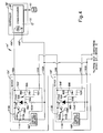
interconnection 44, and the associatedelectronic switches 54, is shown in Fig. 3. In this example thedevices connection line 46B is the communication drive line and theconnection line 46A is the return line. Theconnection line 46B connects thecentral controller 38 to each of thecontrol circuits 18 of the restraint system devices 12 (i.e., the parallel connection). Theconnection line 46A is daisy-chained between the plurality of restraint system devices 12 (i.e., the series connection). At eachrestraint system device 12, theconnection line 46B is connected to an input port 60 of the restraint system device. Theconnection line 46A is connected to a return port 62 of therestraint system device 12. - At each
restraint system device 12, theelectronic switch 54 includes an N-channel MOSFET 64. Focusing on the firstrestraint system device 12A, thesource 66A andsubstrate 68A of the N-channel MOSFET 64A are connected together and are connected to thereturn port 62A of thedevice 12A. Thedrain 70A of the N-channel MOSFET 64A is connected to adaisy chain port 72A of therestraint system device 12A. A segment of theconnection line 46A extends from thedaisy chain port 72A of therestraint system device 12A to thereturn port 62B of the next, downstreamrestraint system device 12B (i.e., in the direction away from the central controller 38). - Still focusing on the first
restraint system device 12A, thegate 74A of the N-channel MOSFET 64A is connected to a control node 76A, which is connected, in turn to thecontrol circuitry 18A of therestraint system device 12A. Aresistor 78A couples the control node 76A to theinput port 60A. Azener diode 80A is operative between the control node 76A and thereturn port 62A. Thezener diode 80A protects the N-channel MOSFET 64A from damage when the voltage atinput port 60A relative to returnport 62A exceeds the maximum gate to source voltage of the MOSFET. Thecontrol circuitry 18A is connected to theinput port 60A and thereturn port 62A. The secondrestraint system device 12B has the same structure identified by a suffix "B". - After the
central controller 38 has finished programming (i.e., establishing an address) therestraint system device 12A, thecontrol circuitry 18A "closes" theelectronic switch 54A by controlling the control node 76A (i.e., thegate 74A of the N-channel MOSFET 64). Specifically, prior to therestraint system device 12A being programmed, thecontrol circuitry 18A biases the MOSFET 64 "OFF". When the MOSFET 64 is "OFF", thereturn port 62A of therestraint system device 12A is not connected to thedaisy chain port 72A of therestraint system device 12A. Once therestraint system device 12A is programmed, thecontrol circuitry 18A biases theMOSFET 64A "ON". This, in effect, "closes" theswitch 54A which connects thereturn port 62A to thedaisy chain port 72A. Thereturn port 62B of the nextrestraint system device 12B (device 2) is connected to thecentral controller 38 through theelectronic switch 54A of the firstrestraint system device 12A (device 1). - This daisy chain process of programming the
respective devices 12 continues until all have been programmed (i.e., given associated addresses). Assume that within thesystem 10, a restraint system device 12X was to be replaced. Restraint system device 12X can be any one of thedevices 12A-12N. Once placed in the daisy chain, the MOSFET 64X of the device 12X would be biased "OFF" since the control circuit 18X of device 12X has not yet been programmed. This would "break" the daisy chain connection, and all, if any, devices downstream of device 12X would be non-responsive to thecentral controller 38 since theircontrol circuits 18 would lose their ground connection. - Once the new device 12X is connected,
controller 38 can detect such occurrence and proceed to send the appropriate signal(s) to program the controller 18X. It should be appreciated that once device 12X is connected in thesystem 10, its associated control circuit 18X is grounded through the device 18(X-1), if any. Once device 18X is programmed, the control circuit 18X would bias its associated MOSFET 64X "ON" to complete the serially connected daisy chain. - Fig. 4 illustrates another embodiment of the present invention using a P-channel MOSFET as the switch 54'. In the embodiment of Fig. 4, a prime (i.e., " ' ") is added to the alpha-numeric numbers used above to identify components generically above (Fig. 1). The prime (Fig. 4) designates that the identified element of this embodiment has a function similar to its earlier mentioned counterpart, but has a different structure. The use of alphabetic suffixes is the same as its use above.
- The
connection line 46A' (Fig. 4) is connected to the central controller 38' as the driven connection line and theconnection line 46B' is connected to the controller as the return line. Theconnection line 46A' is daisy-chained among the plurality of restraint system devices 12' and theconnection line 46B' is connected to the plurality of restraint system devices in a parallel connection arrangement. - Within the electronic switch 54' at each restraint system device 12', a P-channel MOSFET 84 is provided. The source 86 and substrate 88 of the P-channel MOSFET 84 are connected together and are connected to an input port 90 of the restraint system device 12'. For the first
restraint system device 12A' (device 1), theinput port 90A is connected to theline 46A' from thecentral controller 38. Thedrain 92A of the P-channel MOSFET 84A is connected to adaisy chain port 94A. - The
daisy chain port 94A of the firstrestraint system device 12A' (device 1) is connected to theinput port 90B of the secondrestraint system device 12B' (device 2). Accordingly, the daisy chain along theconnection line 46A' is through the P-channel MOSFETs 84. - Focusing again on the first
restraint system device 12A', thegate 96A of the P-channel MOSFET 84A is connected to agate node 98A.Zener diode 100A is operatively connected between theinput port 90A and thegate node 98A. Thegate node 98A is connected to areturn port 102A, via aresistor 104A. Thegate node 98A is also connected to acollector 106A of aPNP transistor 108A. Theemitter 110A of thePNP transistor 108A is connected to theinput port 90A, and thebase 112A of the PNP transistor is connected to acontrol node 114A. Thecontrol node 114A is connected to thecontrol circuitry 18A' and is also connected to theinput port 90A, through aresistor 116A. Accordingly, theresistor 116A is connected between theemitter 110A andbase 112A of thePNP transistor 108A. Further, thecontrol node 114A serves as both the control node for theelectronic switch 54A' and the input node for thecontrol circuitry 18A'. The secondrestraint system device 12B' has the same structure identified by a suffix "B". - When a restraint system device 12' is in an un-programmed state, the control circuitry 18' biases the control node 114 so as to, in turn, bias the P-channel MOSFET 84 "OFF". Once the restraint system device 12' is programmed, the control circuitry 18' biases the control node 114 so as to maintain the P-channel MOSFET 84 "ON". Thus, the input port 90 is connected to the daisy chain port 94. The input port 90 of the next restraint system device is, thus, connected to the
central controller 38 through the upstream P-channel MOSFET 84. Programming of all devices 12' is completed initially through the series daisy chain. A replacement devices 12X' would initially break the daisy chain until it is programmed with an address which, in turn, results in its associated switch 54' to close. - From the above description of the invention, those skilled in the art will perceive improvements, changes and modifications. For example, programming of
devices 12 is described above as the establishment of a device address. Those skilled in the art should appreciate that other programming function can be programmed into adevice 12 particularly in a system in which thecontrol circuitry 18 includes a microcomputer. Such improvements, changes and modifications within the skill the of the art are intended to be covered by the appended claims.
Claims (13)
- An occupant restraint system (10) for a vehicle (22), said system comprising:a plurality of controllable occupant restraint system devices (12), each of said restraint system devices (12) having programmable means (18), which is programmable, for permitting control of the respective restraint system device;central control means (38) for providing programming signals and control signals for receipt by said restraint system devices;a connection line (44), connecting said central control means (38) and said restraint system devices (12), for providing communication between said central control means and said restraint system devices;a plurality of communication regulation means (54), connected in series along said connection line (44), each of said communication regulation means (54) being associated with one of said restraint system devices (12) and for regulating communication between said central control means (38) and any restraint system devices (12) down-stream of said associated restraint system device along said connection line from said central control means; anda plurality of enable means, each of said enable means being associated with one of said restraint system devices (12) and for causing said communication regulation means (54) associated with the one restraint system device (12) to permit communication between said central control means (38) and said any restraint system devices (12) down-stream of said one restraint system device in response to said central control means (38) providing a programming signal to said one restraint system device via said connection line (44).
- An occupant restraint system as set forth in claim 1, wherein said plurality of restraint system devices (12) includes at least one sensor device (12E) for sensing a characteristic used for determining vehicle occupant restraint.
- An occupant restraint system as set forth in claim 1, wherein said plurality of restraint system devices (12) includes at least one restraint device (12A) for restraining a vehicle occupant.
- An occupant restraint system as set forth in claim 1, wherein each of said communication regulation means (54) includes an electronic switch having a closed state for permitting communication between said central control means (38) and said any restraint system devices (12) downstream of said associated restraint system device and an open state for preventing communication between said central control means (38) and said any restraint system devices downstream of said associated restraint system device.
- An occupant restraint system as set forth in claim 4, wherein said electronic switch of each communication regulation means (54) includes an N-channel MOSFET (64) having its source and drain connected in said connection line, and wherein said MOSFET (64) of each electronic switch has its gate connected to an associated one of said enable means.
- An occupant restraint system as set forth in claim 5, wherein for each associated group of restraint system device (12), communication regulation means (54) and enable means, said enable means is part of a control circuitry associated with said restraint system device (12), said programmable means (18) of said restraint system device (12) is another part of said associated control circuitry, said control circuitry biases said gate of said MOSFET (64) of said communication regulation means to change said MOSFET (64) from its open state to its closed state when said control circuitry is programmed.
- An occupant restraint system as set forth in claim 4, wherein for each communication regulation means (54), said electronic switch includes a P-channel MOSFET (84) having its source and drain connected in series with said connection line, said electronic switch also including a PNP transistor (108) having its emitter and collector connected between said connection line and a gate of said MOSFET, said PNP transistor (108) having its base connected to said associated enable means.
- An occupant restraint system as set forth in claim 7, wherein for each associated group of restraint system device (12), communication regulation means (54) and enable means, said enable means is part of a control circuitry associated with said restraint system device, said programmable means (18) of said restraint system device (12) is another part of said associated control circuitry, said control circuitry biases said base of said PNP transistor (108) to cause said MOSFET (84) to change from its open state to its closed state when said control circuitry is programmed.
- An occupant restraint system as set forth in claim 1, wherein said central control means (38) includes means for providing each of said programming signals in series over said connection line (44).
- An occupant restraint system as set forth in claim 1, wherein said central control means (38) including means for providing polling signals to determine the position of each restraint system device along said connection line (44).
- An occupant restraint system as set forth in claim 1, wherein each restraint system device (12) has an address provided by said central control means (38) via the programming signal from said central control means (38) to that restraint system device, said central control means (38) being able to communicate with any restraint system device (12) which has been provided with an address.
- A method of configuring and controlling an occupant restraint system (10) for a vehicle (22), the system having a plurality of controllable occupant restraint system device (12), which each have programmable means (18) for permitting control of the respective restraint system device, central control means (38) for providing programming signals and control signals for receipt by the restraint system devices, and a connection line (44) connecting the central control means and the restraint system devices, said method comprising:connecting a plurality of communication regulation means (54) in series along the connection line (44), each of the communication regulation means being associated with a respective restraint system device; andregulating communication at one of the communication regulation means (54), the regulated communication being between the central control means (38) and any restraint system devices (12) down-stream of the restraint system device associated with the one communication regulation means (54) along the connection line (44) from the central control means (38), and the regulation being such that the communication between the central control means (38) and the any restraint system devices (12) down-stream of the associated restraint system device is permitted after the central control means (38) provides a programming signal to the one restraint system device (12) via the connection line (44).
- A method as set forth in claim 12, wherein each programming signal provided by the central control means (38) is intended for only one of the restraint system device (12), each control signal provided by the central control means (38) is intended for one or more of the restraint system devices (12).
Applications Claiming Priority (2)
| Application Number | Priority Date | Filing Date | Title |
|---|---|---|---|
| US955470 | 1997-10-21 | ||
| US08/955,470 US5964815A (en) | 1997-10-21 | 1997-10-21 | Occupant restraint system having serially connected devices, a method for providing the restraint system and a method for using the restraint system |
Publications (3)
| Publication Number | Publication Date |
|---|---|
| EP0911223A2 EP0911223A2 (en) | 1999-04-28 |
| EP0911223A3 EP0911223A3 (en) | 2001-03-14 |
| EP0911223B1 true EP0911223B1 (en) | 2007-02-28 |
Family
ID=25496865
Family Applications (1)
| Application Number | Title | Priority Date | Filing Date |
|---|---|---|---|
| EP98119493A Expired - Lifetime EP0911223B1 (en) | 1997-10-21 | 1998-10-15 | Occupant restraint system having serially connected devices |
Country Status (3)
| Country | Link |
|---|---|
| US (1) | US5964815A (en) |
| EP (1) | EP0911223B1 (en) |
| DE (1) | DE69837182T2 (en) |
Families Citing this family (86)
| Publication number | Priority date | Publication date | Assignee | Title |
|---|---|---|---|---|
| US6168198B1 (en) * | 1992-05-05 | 2001-01-02 | Automotive Technologies International, Inc. | Methods and arrangements for controlling an occupant restraint device in a vehicle |
| US7134687B2 (en) * | 1992-05-05 | 2006-11-14 | Automotive Technologies International, Inc. | Rear view mirror monitor |
| US6910711B1 (en) | 1992-05-05 | 2005-06-28 | Automotive Technologies International, Inc. | Method for controlling deployment of an occupant protection device |
| US6422595B1 (en) | 1992-05-05 | 2002-07-23 | Automotive Technologies International, Inc. | Occupant position sensor and method and arrangement for controlling a vehicular component based on an occupant's position |
| US7467809B2 (en) | 1992-05-05 | 2008-12-23 | Automotive Technologies International, Inc. | Vehicular occupant characteristic determination system and method |
| US6942248B2 (en) | 1992-05-05 | 2005-09-13 | Automotive Technologies International, Inc. | Occupant restraint device control system and method |
| US6820897B2 (en) | 1992-05-05 | 2004-11-23 | Automotive Technologies International, Inc. | Vehicle object detection system and method |
| US6533316B2 (en) | 1995-06-07 | 2003-03-18 | Automotive Technologies International, Inc. | Automotive electronic safety network |
| US6905135B2 (en) | 1995-06-07 | 2005-06-14 | Automotive Technologies International, Inc. | Inflator system |
| US6733036B2 (en) * | 1995-06-07 | 2004-05-11 | Automotive Technologies International, Inc. | Automotive electronic safety network |
| US6648367B2 (en) | 1995-06-07 | 2003-11-18 | Automotive Technologies International Inc. | Integrated occupant protection system |
| US7832762B2 (en) * | 1995-06-07 | 2010-11-16 | Automotive Technologies International, Inc. | Vehicular bus including crash sensor or occupant protection system control module |
| US9443358B2 (en) | 1995-06-07 | 2016-09-13 | Automotive Vehicular Sciences LLC | Vehicle software upgrade techniques |
| US7580782B2 (en) * | 1995-10-30 | 2009-08-25 | Automotive Technologies International, Inc. | Vehicular electronic system with crash sensors and occupant protection systems |
| US7774115B2 (en) * | 1995-10-30 | 2010-08-10 | Automotive Technologies International, Inc. | Electronics-containing airbag module |
| US7744122B2 (en) | 1995-12-12 | 2010-06-29 | Automotive Technologies International, Inc. | Driver side aspirated airbags |
| DE19616293A1 (en) * | 1996-04-24 | 1997-10-30 | Bosch Gmbh Robert | Bus system for the transmission of messages |
| DE19648268A1 (en) * | 1996-11-21 | 1998-05-28 | Siemens Ag | Vehicle seat with a control device |
| US6412391B1 (en) | 1997-05-12 | 2002-07-02 | Southwest Research Institute | Reactive personnel protection system and method |
| JP3572921B2 (en) * | 1998-01-06 | 2004-10-06 | 日産自動車株式会社 | Air bag device |
| JP4112020B2 (en) * | 1998-01-16 | 2008-07-02 | シンボル テクノロジーズ インコーポレイテッド | Wireless LAN infrastructure |
| DE19813957C2 (en) * | 1998-03-28 | 2003-06-18 | Conti Temic Microelectronic | Occupant protection system with a central unit, sensors and several control modules communicatively connected by means of a BUS system for triggering occupant protection devices |
| DE19813921A1 (en) * | 1998-03-28 | 1999-09-30 | Telefunken Microelectron | Method for operating a restraint system networked via a bus line in the event of a faulty power supply |
| US6305708B2 (en) * | 1998-06-29 | 2001-10-23 | Motorola, Inc. | Air bag deployment system and method for monitoring same |
| US10240935B2 (en) | 1998-10-22 | 2019-03-26 | American Vehicular Sciences Llc | Vehicle software upgrade techniques |
| US6273460B1 (en) * | 1999-05-27 | 2001-08-14 | Daimlerchrysler Corporation | Smart remote indicator module |
| US6439602B2 (en) | 1999-05-27 | 2002-08-27 | Daimlerchrysler Corporation | Remote indicator module |
| US6212457B1 (en) * | 1999-08-05 | 2001-04-03 | Trw Inc. | Mixed parallel and daisy chain bus architecture in a vehicle safety system |
| US6448671B1 (en) * | 1999-08-05 | 2002-09-10 | Trw Inc. | Distributed vehicle safety system having fault protection |
| US6220628B1 (en) * | 1999-12-01 | 2001-04-24 | Trw Inc. | Vehicle occupant protection apparatus and method having multiple stage control |
| US6302439B1 (en) * | 2000-02-01 | 2001-10-16 | Trw Inc. | Distributed occupant protection system and method with cooperative central and distributed protection module actuation control |
| US7278657B1 (en) * | 2000-02-01 | 2007-10-09 | Trw Automotive U.S. Llc | Method and apparatus for controlling an actuatable occupant protection device using an ultrasonic sensor |
| US6296273B1 (en) * | 2000-02-22 | 2001-10-02 | David G. Lewallen | Automobile airbag deactivation system |
| US7173922B2 (en) * | 2000-03-17 | 2007-02-06 | Symbol Technologies, Inc. | Multiple wireless local area networks occupying overlapping physical spaces |
| US7173923B2 (en) * | 2000-03-17 | 2007-02-06 | Symbol Technologies, Inc. | Security in multiple wireless local area networks |
| US6584907B2 (en) * | 2000-03-17 | 2003-07-01 | Ensign-Bickford Aerospace & Defense Company | Ordnance firing system |
| DE10115409A1 (en) * | 2001-03-29 | 2002-10-10 | Bosch Gmbh Robert | Bus master for a bus for connecting sensors and / or ignition devices |
| DE10115410A1 (en) * | 2001-03-29 | 2002-10-24 | Bosch Gmbh Robert | Bus station for connection to a bus system for restraint devices and / or sensors |
| US6480144B1 (en) | 2002-01-30 | 2002-11-12 | Ford Global Technologies, Inc. | Wireless communication between countermeasure devices |
| DE10225888B4 (en) * | 2002-06-11 | 2007-06-21 | Daimlerchrysler Ag | Modular chassis system |
| US6961645B2 (en) | 2002-06-18 | 2005-11-01 | Siemens Vdo Automotive Corporation | Multiple-satellite sensor algorithm wake up and reset strategy for an inflatable restraint system |
| US20040224557A1 (en) * | 2002-11-05 | 2004-11-11 | Wight Barbara Jane | System and method of detecting and particularly identifying controlled devices |
| JP2004312804A (en) * | 2003-04-02 | 2004-11-04 | Asmo Co Ltd | Actuator device and actuator system |
| US20050165538A1 (en) * | 2004-01-28 | 2005-07-28 | Aisin Seiki Kabushiki Kaisha | Load-detecting device for an object on a seat |
| DE102004015125B4 (en) * | 2004-03-27 | 2017-09-14 | Robert Bosch Gmbh | Device for controlling personal protective equipment |
| US20080259787A1 (en) * | 2004-05-28 | 2008-10-23 | Symbol Technologies, Inc. | Backup cell controller |
| EP1683684A1 (en) * | 2005-01-21 | 2006-07-26 | IEE INTERNATIONAL ELECTRONICS & ENGINEERING S.A. | Checkable seat occupancy sensor |
| DE102005036287B3 (en) * | 2005-08-02 | 2007-05-16 | Infineon Technologies Ag | Method for power supply of sensors in a sensor arrangement and sensor arrangement |
| US20070067082A1 (en) * | 2005-09-20 | 2007-03-22 | Robert Bosch Gmbh | Integrated vehicle system |
| JP2007215102A (en) * | 2006-02-13 | 2007-08-23 | Denso Corp | Communication device |
| US20070198139A1 (en) * | 2006-02-21 | 2007-08-23 | Colm Boran | Auto-address multi-sensor network |
| DE102007045561B4 (en) * | 2007-09-24 | 2018-02-15 | Robert Bosch Gmbh | Method for operating a driver assistance system |
| US7746114B2 (en) | 2007-11-14 | 2010-06-29 | Denso Corporation | Bus switch and electronic switch |
| JP5075724B2 (en) * | 2008-04-18 | 2012-11-21 | 株式会社ケーヒン | Occupant protection control device and occupant protection system |
| JP4596068B2 (en) | 2008-11-12 | 2010-12-08 | 株式会社デンソー | Communication device for occupant protection system |
| US9817085B2 (en) * | 2012-03-15 | 2017-11-14 | Infineon Technologies Ag | Frequency doubling of xMR signals |
| GB201207450D0 (en) * | 2012-04-26 | 2012-06-13 | Secr Defence | An electrical pulse splitter for an explosives system |
| DE102015204714A1 (en) * | 2015-03-16 | 2016-09-22 | Robert Bosch Gmbh | Subscriber station for a bus system and method for data transmission in a bus system |
| US9840220B2 (en) * | 2015-04-27 | 2017-12-12 | L & B Manufacturing, Inc. | Wireless airbag control system |
| JP2018135060A (en) * | 2017-02-23 | 2018-08-30 | 株式会社デンソー | Crew member protection system |
| US12233756B2 (en) | 2018-05-04 | 2025-02-25 | Lear Corporation | Track system with a support member |
| US10926667B2 (en) | 2018-05-04 | 2021-02-23 | Lear Corporation | Track assembly |
| US10882420B2 (en) | 2019-03-08 | 2021-01-05 | Lear Corporation | Track assembly |
| US11358497B2 (en) | 2018-05-04 | 2022-06-14 | Lear Corporation | Track system having a rolling member |
| US11040638B2 (en) | 2018-05-04 | 2021-06-22 | Lear Corporation | Track assembly |
| US10562414B2 (en) | 2018-05-04 | 2020-02-18 | Lear Corporation | Track assembly |
| US11040639B2 (en) | 2018-05-04 | 2021-06-22 | Lear Corporation | Track assembly |
| US10906431B2 (en) | 2018-05-04 | 2021-02-02 | Lear Corporation | Track assembly |
| US11225201B2 (en) | 2018-12-10 | 2022-01-18 | Lear Corporation | Track assembly |
| US11440482B2 (en) | 2018-12-10 | 2022-09-13 | Lear Corporation | Track assembly |
| US10855037B2 (en) | 2018-12-17 | 2020-12-01 | Lear Corporation | Support assembly with a support member and a track assembly |
| US11117538B2 (en) | 2018-12-17 | 2021-09-14 | Lear Corporation | Electrical assembly |
| US11613220B2 (en) | 2018-12-17 | 2023-03-28 | Lear Corporation | Electrical assembly |
| US10950977B2 (en) | 2018-12-18 | 2021-03-16 | Lear Corporation | Track assembly for a vehicle component |
| US11975665B2 (en) | 2019-02-20 | 2024-05-07 | Lear Corporation | Electrical assembly |
| US11040653B2 (en) | 2019-02-25 | 2021-06-22 | Lear Corporation | Track assembly |
| US11807142B2 (en) | 2019-03-06 | 2023-11-07 | Lear Corporation | Electrical track assembly |
| US11299075B2 (en) | 2019-03-06 | 2022-04-12 | Lear Corporation | Electrical assembly |
| US10795845B1 (en) * | 2019-08-23 | 2020-10-06 | Texas Instruments Incorporated | Method and system for auto-addressing nodes on a communication bus |
| US11323114B2 (en) | 2019-10-04 | 2022-05-03 | Lear Corporation | Electrical system |
| US11463083B2 (en) | 2019-10-04 | 2022-10-04 | Lear Corporation | Electrical system |
| US11634101B2 (en) | 2019-10-04 | 2023-04-25 | Lear Corporation | Removable component system |
| US11677233B2 (en) * | 2019-11-12 | 2023-06-13 | Eaton Intelligent Power Limited | Smart bus plug remote actuation, monitoring, and control |
| DE102021104018B4 (en) | 2020-02-21 | 2023-11-09 | Lear Corporation | Rail system with a support element, method for operating a rail system |
| US11906028B2 (en) | 2020-02-21 | 2024-02-20 | Lear Corporation | Track system with a support member |
| US11505141B2 (en) | 2020-10-23 | 2022-11-22 | Lear Corporation | Electrical system with track assembly and support assembly |
Family Cites Families (22)
| Publication number | Priority date | Publication date | Assignee | Title |
|---|---|---|---|---|
| US3768409A (en) * | 1972-11-10 | 1973-10-30 | Us Navy | Binary explosive logic network |
| DE2945122A1 (en) * | 1978-02-01 | 1980-05-22 | Ici Ltd | ELECTRIC DELAY DEVICE |
| US4496010A (en) * | 1982-07-02 | 1985-01-29 | Schlumberger Technology Corporation | Single-wire selective performation system |
| US4527636A (en) * | 1982-07-02 | 1985-07-09 | Schlumberger Technology Corporation | Single-wire selective perforation system having firing safeguards |
| US4674047A (en) * | 1984-01-31 | 1987-06-16 | The Curators Of The University Of Missouri | Integrated detonator delay circuits and firing console |
| US4689786A (en) * | 1985-03-21 | 1987-08-25 | Apple Computer, Inc. | Local area network with self assigned address method |
| GB2190730B (en) * | 1986-05-22 | 1990-10-24 | Detonix Close Corp | Detonator firing element |
| ZA875014B (en) * | 1987-07-09 | 1988-01-18 | ||
| JPH01162967A (en) * | 1987-12-18 | 1989-06-27 | Fujitsu Ltd | Method and device for interruption processing |
| US4843964A (en) * | 1988-02-01 | 1989-07-04 | The United States Of America As Represented By The United States Department Of Energy | Smart explosive igniter |
| JPH02262444A (en) * | 1989-03-31 | 1990-10-25 | Aisin Seiki Co Ltd | Attitude control of installation on automobile and attitude control device |
| US4986183A (en) * | 1989-10-24 | 1991-01-22 | Atlas Powder Company | Method and apparatus for calibration of electronic delay detonation circuits |
| JPH0694996B2 (en) * | 1989-11-24 | 1994-11-24 | 繁明 國友 | Fireworks ignition device |
| US5287531A (en) * | 1990-10-31 | 1994-02-15 | Compaq Computer Corp. | Daisy-chained serial shift register for determining configuration of removable circuit boards in a computer system |
| US5446442A (en) * | 1992-03-31 | 1995-08-29 | Siemens Aktiengesellschaft | Circuit arrangement for triggering a vehicle passenger protection system |
| US5291680A (en) * | 1992-09-19 | 1994-03-08 | The United States Of America As Represented By The Secretary Of The Army | Grenade launching apparatus |
| US5404460A (en) * | 1994-01-28 | 1995-04-04 | Vlsi Technology, Inc. | Method for configuring multiple identical serial I/O devices to unique addresses through a serial bus |
| DE4425845A1 (en) * | 1994-07-21 | 1996-01-25 | Telefunken Microelectron | Data transmission method in a data processing system suitable for use in motor vehicles |
| EP0788929A1 (en) * | 1996-02-12 | 1997-08-13 | Applied Power Inc. | Communication system for data transmission in a control device of a car |
| AU1260697A (en) * | 1996-02-21 | 1997-08-28 | Consolidated Technologies International | Multiplexed electrical system having a central controller and programmable control nodes |
| US5825098A (en) * | 1997-02-21 | 1998-10-20 | Breed Automotive Technologies, Inc. | Vehicle safety device controller |
| US5835873A (en) * | 1997-02-21 | 1998-11-10 | Breed Automotive Technology, Inc. | Vehicle safety system with safety device controllers |
-
1997
- 1997-10-21 US US08/955,470 patent/US5964815A/en not_active Expired - Lifetime
-
1998
- 1998-10-15 EP EP98119493A patent/EP0911223B1/en not_active Expired - Lifetime
- 1998-10-15 DE DE69837182T patent/DE69837182T2/en not_active Expired - Lifetime
Also Published As
| Publication number | Publication date |
|---|---|
| DE69837182T2 (en) | 2007-11-22 |
| DE69837182D1 (en) | 2007-04-12 |
| EP0911223A3 (en) | 2001-03-14 |
| EP0911223A2 (en) | 1999-04-28 |
| US5964815A (en) | 1999-10-12 |
Similar Documents
| Publication | Publication Date | Title |
|---|---|---|
| US5964815A (en) | Occupant restraint system having serially connected devices, a method for providing the restraint system and a method for using the restraint system | |
| US6212457B1 (en) | Mixed parallel and daisy chain bus architecture in a vehicle safety system | |
| US6449545B1 (en) | Method for data transfer in a restraint system connected to a bus line | |
| US20070233919A1 (en) | Communication apparatus | |
| US6302439B1 (en) | Distributed occupant protection system and method with cooperative central and distributed protection module actuation control | |
| US6448671B1 (en) | Distributed vehicle safety system having fault protection | |
| KR100343268B1 (en) | Method and device for controlling data transmission between two modules located in a motor vehicle | |
| JPH11337427A (en) | Apparatus and method for specifying part of body of near crew by sensor matrix | |
| US6072246A (en) | Process for triggering a passive occupant safety protection system for motor vehicles | |
| US6249228B1 (en) | Vehicle occupant protection device and system having an anti-theft, anti-tamper feature | |
| US11167710B2 (en) | Airbag driving apparatus for vehicle and control method thereof | |
| EP0957013B1 (en) | Ignition control system for a passive safety device with interconnected airbag control and roll-over control | |
| US6218738B1 (en) | Ignition control method in passive safety device for vehicle | |
| US6070687A (en) | Vehicle occupant restraint device, system, and method having an anti-theft feature | |
| US6293583B1 (en) | Apparatus for activating passive safety device | |
| US6045156A (en) | Supplement restraint system having deployment inhibit apparatus | |
| US6236920B1 (en) | Distributed vehicle safety with bus connection components having a remotely-located initiation electronics arrangement and a bus tap arrangement | |
| WO1998043853A1 (en) | Control apparatus for passenger restraining safety devices | |
| US6363307B1 (en) | Control system for occupant protection apparatus | |
| JP4591383B2 (en) | Bus communication system | |
| US6273460B1 (en) | Smart remote indicator module | |
| US6304004B1 (en) | Apparatus for actuating a passenger safety system | |
| JP2001187558A (en) | Transportation means passenger crash protection device having multistage control | |
| US20020079679A1 (en) | Automatic impact severity compensation system | |
| JP2004255911A (en) | Airbag system |
Legal Events
| Date | Code | Title | Description |
|---|---|---|---|
| PUAI | Public reference made under article 153(3) epc to a published international application that has entered the european phase |
Free format text: ORIGINAL CODE: 0009012 |
|
| AK | Designated contracting states |
Kind code of ref document: A2 Designated state(s): DE FR GB |
|
| AX | Request for extension of the european patent |
Free format text: AL;LT;LV;MK;RO;SI |
|
| PUAL | Search report despatched |
Free format text: ORIGINAL CODE: 0009013 |
|
| AK | Designated contracting states |
Kind code of ref document: A3 Designated state(s): AT BE CH CY DE DK ES FI FR GB GR IE IT LI LU MC NL PT SE |
|
| AX | Request for extension of the european patent |
Free format text: AL;LT;LV;MK;RO;SI |
|
| RIC1 | Information provided on ipc code assigned before grant |
Free format text: 7B 60R 21/00 A, 7B 60R 16/02 B |
|
| 17P | Request for examination filed |
Effective date: 20010911 |
|
| AKX | Designation fees paid |
Free format text: DE FR GB |
|
| RAP1 | Party data changed (applicant data changed or rights of an application transferred) |
Owner name: TRW AUTOMOTIVE U.S. LLC |
|
| GRAP | Despatch of communication of intention to grant a patent |
Free format text: ORIGINAL CODE: EPIDOSNIGR1 |
|
| GRAS | Grant fee paid |
Free format text: ORIGINAL CODE: EPIDOSNIGR3 |
|
| GRAA | (expected) grant |
Free format text: ORIGINAL CODE: 0009210 |
|
| AK | Designated contracting states |
Kind code of ref document: B1 Designated state(s): DE FR GB |
|
| REG | Reference to a national code |
Ref country code: GB Ref legal event code: FG4D |
|
| REF | Corresponds to: |
Ref document number: 69837182 Country of ref document: DE Date of ref document: 20070412 Kind code of ref document: P |
|
| EN | Fr: translation not filed | ||
| PLBE | No opposition filed within time limit |
Free format text: ORIGINAL CODE: 0009261 |
|
| STAA | Information on the status of an ep patent application or granted ep patent |
Free format text: STATUS: NO OPPOSITION FILED WITHIN TIME LIMIT |
|
| 26N | No opposition filed |
Effective date: 20071129 |
|
| PG25 | Lapsed in a contracting state [announced via postgrant information from national office to epo] |
Ref country code: FR Free format text: LAPSE BECAUSE OF FAILURE TO SUBMIT A TRANSLATION OF THE DESCRIPTION OR TO PAY THE FEE WITHIN THE PRESCRIBED TIME-LIMIT Effective date: 20071019 |
|
| GBPC | Gb: european patent ceased through non-payment of renewal fee |
Effective date: 20071015 |
|
| PG25 | Lapsed in a contracting state [announced via postgrant information from national office to epo] |
Ref country code: GB Free format text: LAPSE BECAUSE OF NON-PAYMENT OF DUE FEES Effective date: 20071015 Ref country code: FR Free format text: LAPSE BECAUSE OF FAILURE TO SUBMIT A TRANSLATION OF THE DESCRIPTION OR TO PAY THE FEE WITHIN THE PRESCRIBED TIME-LIMIT Effective date: 20070228 |
|
| PGFP | Annual fee paid to national office [announced via postgrant information from national office to epo] |
Ref country code: DE Payment date: 20171027 Year of fee payment: 20 |
|
| REG | Reference to a national code |
Ref country code: DE Ref legal event code: R071 Ref document number: 69837182 Country of ref document: DE |