EP0911190A1 - Tyre removal machine - Google Patents
Tyre removal machine Download PDFInfo
- Publication number
- EP0911190A1 EP0911190A1 EP98203156A EP98203156A EP0911190A1 EP 0911190 A1 EP0911190 A1 EP 0911190A1 EP 98203156 A EP98203156 A EP 98203156A EP 98203156 A EP98203156 A EP 98203156A EP 0911190 A1 EP0911190 A1 EP 0911190A1
- Authority
- EP
- European Patent Office
- Prior art keywords
- tyre
- removal machine
- current
- phase
- motor
- Prior art date
- Legal status (The legal status is an assumption and is not a legal conclusion. Google has not performed a legal analysis and makes no representation as to the accuracy of the status listed.)
- Granted
Links
- 238000010521 absorption reaction Methods 0.000 claims abstract 3
- 239000011324 bead Substances 0.000 claims abstract 2
- 230000005284 excitation Effects 0.000 claims abstract 2
- 230000005611 electricity Effects 0.000 description 5
- 230000006698 induction Effects 0.000 description 4
- 230000007423 decrease Effects 0.000 description 3
- 238000010586 diagram Methods 0.000 description 2
- 238000001914 filtration Methods 0.000 description 1
- 238000004519 manufacturing process Methods 0.000 description 1
- 238000005259 measurement Methods 0.000 description 1
- 239000002184 metal Substances 0.000 description 1
- 230000005612 types of electricity Effects 0.000 description 1
- 238000004804 winding Methods 0.000 description 1
Images


Classifications
-
- B—PERFORMING OPERATIONS; TRANSPORTING
- B60—VEHICLES IN GENERAL
- B60C—VEHICLE TYRES; TYRE INFLATION; TYRE CHANGING; CONNECTING VALVES TO INFLATABLE ELASTIC BODIES IN GENERAL; DEVICES OR ARRANGEMENTS RELATED TO TYRES
- B60C25/00—Apparatus or tools adapted for mounting, removing or inspecting tyres
- B60C25/01—Apparatus or tools adapted for mounting, removing or inspecting tyres for removing tyres from or mounting tyres on wheels
- B60C25/05—Machines
- B60C25/132—Machines for removing and mounting tyres
Definitions
- This invention concerns machines for mounting and removing a tyre on and from a wheel rim, and in particular relates to the means for their operation.
- Known machines for tyre mounting and removal on and from a wheel rim comprise an outer sheet metal casing, on the top of which there is located a rotary platform provided with self-centering means for locking the wheel rim.
- a vertical structure which supports, and locks in the required position, a horizontal arm, of which that end overlying the rotary platform supports the slide seat of a vertical arm.
- a tool which acts against the tyre edge to urge it below the edge of the wheel rim or to extract it therefrom.
- Said rotary platform is driven by an electric motor positioned within the casing via a connection shaft, between which a speed step-down gear is interposed.
- the electric motor used for driving the machine can be of three-phase induction or single-phase induction type.
- the electricity supply voltage differs for different countries, for example in Italy the three-phase a.c. supply voltage is 380V and the single-phase supply is at 220V, whereas in the United States the electricity supply is single-phase a.c. at 110V.
- a three-phase or single-phase induction motor is known to have a characteristic torque curve in which the torque varies substantially as the r.p.m. varies, within a very narrow range.
- the object of the invention is to provide a machine for tyre mounting and removal on and from a wheel rim which overcomes the aforesaid drawbacks by virtue of the characteristics defined in the claims.
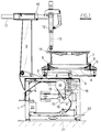
- Said figures show the casing 1, from the top 2 of which there emerges the shaft 3 which rotatably supports the platform 4.
- Said circular platform 4 is provided with four usual radial slots, not shown, within which there move slides 5 upperly provided with jaws 6 for locking the wheel rim 7 in the working position.
- the slides 5 are driven by a usual pneumatic unit 8 supported within the lower part of the circular platform 4, as shown in Figure 1.
- a guide 12 of vertical axis which receives and can lock thereto a rod 13, to the lower end of which the tool 14 which acts against the tyre edge is connected.
- the circular platform 4 is rotated about its axis by the electric motor 15, means being interposed for reducing the rotational speed of the motor shaft.
- these means comprise a step-down gear 16 and the pair of pulleys 17 and 18 between which the belt 19 extends.
- the electric motor 15, shown schematically in Figure 2 is of series-excited single-phase type supplying a power output of between 350W and 600W with an absorbed current of between 10A and 15A.
- Said figure shows the stator 23 with its stator winding 24, the rotor 25 provided with brushes 26, and the terminal block 27 to which the ends of the stator and rotor circuits, 240, 241 and 260, 261 respectively, are connected.
- the leads 280, 281 from a speed indicator of tachometer type, and the leads 290, 291 from the motor thermal protection device, are also connected to the terminal block 27.
- an electronic card 20 for controlling and protecting the electric motor, and a reversing switch 21 operated by the start-stop pedal 22 of the tyre removal machine.
- Said electric motor 15 is powered with 220V a.c. in those regions in which this electrical voltage is available, or otherwise at 110V a.c.
- the electronic card 20 will comprise a rectifier stage to rectify the 110V a.c. supply to about 150V d.c. (rectified), to provide the power required for mounting and/or removing the tyre on or from the wheel rim.
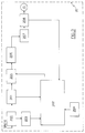
- the electronic card 20 for powering the motor with a d.c. voltage of about 150V is shown in the block diagram of Figure 3. Said figure shows an initial stage 200 comprising components for filtering out the contaminating harmonics present in the mains a.c. supply and the protection devices at the input to the card 20.
- stage 201 Downstream of the stage 200 there is a stage 201 for measuring the current absorbed by the electric motor 15 and consisting for example of a usual ammeter-transformer which measures the current through the motor supply line and feeds the signal obtained to a measurement and control circuit represented by the block 202.
- the electric circuits represented by the block 202 which are not shown because they are of usual type, are powered by a power unit indicated by 203 in Figure 3.
- said block 202 comprises an input stage consisting of a rectifier and filter in which the a.c. signal from the ammeter-transformer is rectified, a comparator in which said rectified current signal is compared with a reference current value, generally the maximum current allowable through the motor to not exceed the desired torque, and set in the block 204, a memory circuit in which the measured value of said current signal is memorized, and a circuit for opening and closing the relay represented by the block 205.
- a block 207 comprising a motor filter and a block 208 consisting of a reversing switch which acts as a general switch and enables the direction of rotation of the rotor of the electric motor 15 to be reversed by acting on the contacts of the terminal block 27.
- the electric current absorbed by the line is proportional to the resistant torque applied to the shaft of the electric motor 15, which itself depends on the force applied to the tool 14 when it acts between the edge of the wheel rim and the edge of the tyre.
- the absorbed current must always be less than a value determined by the manufacturer of the electric motor 15 in order not to damage the rotor brushes 26.
- this determined value is 15A, and is preset in the block 204 to provide an operating limit.
- the control circuit for the relay 205 opens this latter to interrupt current feed to the electric motor 15.
- the described tyre removal machine can also be powered with 220V a.c. by replacing the electronic card 20 with an electronic card similar to that shown but without the rectifier stage 206.
Landscapes
- Engineering & Computer Science (AREA)
- Mechanical Engineering (AREA)
- Testing Of Balance (AREA)
- Moulds For Moulding Plastics Or The Like (AREA)
- Protection Of Generators And Motors (AREA)
- Control Of Electric Motors In General (AREA)
- Vehicle Cleaning, Maintenance, Repair, Refitting, And Outriggers (AREA)
- Arrangement Or Mounting Of Propulsion Units For Vehicles (AREA)
Abstract
Description
- This invention concerns machines for mounting and removing a tyre on and from a wheel rim, and in particular relates to the means for their operation.
- Known machines for tyre mounting and removal on and from a wheel rim comprise an outer sheet metal casing, on the top of which there is located a rotary platform provided with self-centering means for locking the wheel rim.
- To the side of the rotary platform there extends a vertical structure which supports, and locks in the required position, a horizontal arm, of which that end overlying the rotary platform supports the slide seat of a vertical arm. To the lower end of said vertical arm there is connected a tool which acts against the tyre edge to urge it below the edge of the wheel rim or to extract it therefrom.
- Said rotary platform is driven by an electric motor positioned within the casing via a connection shaft, between which a speed step-down gear is interposed.
- In those regions in which electricity for industrial use is distributed via a three-phase alternating current grid, the electric motor used for driving the machine can be of three-phase induction or single-phase induction type.
- However in those regions in which electricity is distributed via a single-phase grid a single-phase induction motor is used.
- The electricity supply voltage differs for different countries, for example in Italy the three-phase a.c. supply voltage is 380V and the single-phase supply is at 220V, whereas in the United States the electricity supply is single-phase a.c. at 110V.
- This requires the manufacturers of this type of machine to diversify production in accordance with the voltage and type of electricity grid in the regions in which the product is to be sold.
- This is made more difficult by the fact that tyre removal machines require their rotary platform to be operated with a torque which has a substantial value at the low r.p.m. at which the platform rotates when the tool is in use.
- In this respect, a three-phase or single-phase induction motor is known to have a characteristic torque curve in which the torque varies substantially as the r.p.m. varies, within a very narrow range.
- There is therefore a requirement for a machine for mounting and removing tyres on and from a wheel rim, the operation of which satisfies this torque requirement independently of the voltage and type of the power grid electricity.
- The object of the invention is to provide a machine for tyre mounting and removal on and from a wheel rim which overcomes the aforesaid drawbacks by virtue of the characteristics defined in the claims.
- The operational and constructional characteristics of the invention will be more apparent from the ensuing description of a preferred embodiment thereof given by way of non-limiting example with reference to the accompanying drawings.
- Figure 1 is a section through the machine of the invention.
- Figure 2 is a schematic view of the drive motor for the machine of the invention.
- Figure 3 shows the block diagram of the control and protection circuit for the machine of the invention.
- Figure 4 shows the characteristic torque/r.p.m. curve of the electric motor used by the invention.
-
- Said figures show the
casing 1, from thetop 2 of which there emerges theshaft 3 which rotatably supports theplatform 4. - Said
circular platform 4 is provided with four usual radial slots, not shown, within which there moveslides 5 upperly provided withjaws 6 for locking thewheel rim 7 in the working position. Theslides 5 are driven by a usualpneumatic unit 8 supported within the lower part of thecircular platform 4, as shown in Figure 1. - To the side of the
circular platform 4 there upwardly extends the column 9, to the upper end of which there is connected a horizontal guide 10 within which theshaped rod 11 moves. - At the end of said
shaped rod 11 there is supported aguide 12 of vertical axis, which receives and can lock thereto arod 13, to the lower end of which thetool 14 which acts against the tyre edge is connected. - The
circular platform 4 is rotated about its axis by theelectric motor 15, means being interposed for reducing the rotational speed of the motor shaft. - Specifically, these means comprise a step-down
gear 16 and the pair ofpulleys belt 19 extends. - The
electric motor 15, shown schematically in Figure 2, is of series-excited single-phase type supplying a power output of between 350W and 600W with an absorbed current of between 10A and 15A. - Said figure shows the
stator 23 with its stator winding 24, therotor 25 provided withbrushes 26, and theterminal block 27 to which the ends of the stator and rotor circuits, 240, 241 and 260, 261 respectively, are connected. - The
leads terminal block 27. - The characteristic torque/r.p.m. curve for a series-excited motor is shown in Figure 4. This figure shows that as the resistant torque increases, the motor r.p.m. decreases and the developed torque increases. Hence this type of motor has an r.p.m. which varies considerably as the load varies, a characteristic well suited to tyre removal machines, in which a low speed is required with high resistant torques, and a high speed when the resistant torque is low.
- Between the power terminals of the
electric motor 15 and the mains line there are connected anelectronic card 20 for controlling and protecting the electric motor, and areversing switch 21 operated by the start-stop pedal 22 of the tyre removal machine. - Said
electric motor 15 is powered with 220V a.c. in those regions in which this electrical voltage is available, or otherwise at 110V a.c. - In this latter case the
electronic card 20 will comprise a rectifier stage to rectify the 110V a.c. supply to about 150V d.c. (rectified), to provide the power required for mounting and/or removing the tyre on or from the wheel rim. - The
electronic card 20 for powering the motor with a d.c. voltage of about 150V is shown in the block diagram of Figure 3. Said figure shows aninitial stage 200 comprising components for filtering out the contaminating harmonics present in the mains a.c. supply and the protection devices at the input to thecard 20. - Downstream of the
stage 200 there is astage 201 for measuring the current absorbed by theelectric motor 15 and consisting for example of a usual ammeter-transformer which measures the current through the motor supply line and feeds the signal obtained to a measurement and control circuit represented by theblock 202. The electric circuits represented by theblock 202, which are not shown because they are of usual type, are powered by a power unit indicated by 203 in Figure 3. - Specifically, said
block 202 comprises an input stage consisting of a rectifier and filter in which the a.c. signal from the ammeter-transformer is rectified, a comparator in which said rectified current signal is compared with a reference current value, generally the maximum current allowable through the motor to not exceed the desired torque, and set in theblock 204, a memory circuit in which the measured value of said current signal is memorized, and a circuit for opening and closing the relay represented by theblock 205. - Downstream of said
block 205 there is a rectifier of usual type, indicated by 206, which rectifies the alternating current required by theelectric motor 15. - Between said
electric motor 15 and theblock 205 there are connected ablock 207 comprising a motor filter and ablock 208 consisting of a reversing switch which acts as a general switch and enables the direction of rotation of the rotor of theelectric motor 15 to be reversed by acting on the contacts of theterminal block 27. - During the operation of the tyre removal machine the electric current absorbed by the line is proportional to the resistant torque applied to the shaft of the
electric motor 15, which itself depends on the force applied to thetool 14 when it acts between the edge of the wheel rim and the edge of the tyre. - If during the mounting or removal of the tyre on or from the wheel rim the tool encounters difficulty in advancing, the resistant torque increases with corresponding motor r.p.m. decrease in accordance with the curve of Figure 4. When the tool overcomes the point of opposition, the resistant torque decreases and the motor r.p.m. increases.
- During the mounting or removal of the tyre on or from the wheel rim, the absorbed current must always be less than a value determined by the manufacturer of the
electric motor 15 in order not to damage therotor brushes 26. In the illustrated example this determined value is 15A, and is preset in theblock 204 to provide an operating limit. - If during the operation of the tyre removal machine the absorbed current exceeds the current value preset in the
block 204, the control circuit for therelay 205 opens this latter to interrupt current feed to theelectric motor 15. - Current feed is restored only after the operator releases the
start pedal 22 of the tyre removal machine, so cancelling the locked state memorized by the memory circuit, the control circuit for therelay 205 then reclosing this latter. - The described tyre removal machine can also be powered with 220V a.c. by replacing the
electronic card 20 with an electronic card similar to that shown but without therectifier stage 206.
Claims (3)
- A tyre removal machine comprising a rotary platform for supporting the wheel, means for acting on the tyre bead and platform operating means, characterised in that the operating means are a single-phase electric motor with series excitation supplying a power output of between 350W and 600W with an absorbed current not exceeding 15A, connected to a single-phase feed line at 110V a.c. via a voltage rectifier, means being provided for limiting current absorption to a predetermined value.
- A tyre removal machine as claimed in claim 1, characterised in that the motor is connected to a single-phase 220V a.c. line without the voltage rectifier being connected therebetween.
- A tyre removal machine as claimed in the preceding claims, characterised in that the current absorption limiting means comprise a current meter, a rectifier, a comparator, a memory circuit and an opening circuit for a relay, which is subsequently closed by releasing the machine operating pedal.
Applications Claiming Priority (2)
| Application Number | Priority Date | Filing Date | Title |
|---|---|---|---|
| IT97RE000077A IT1297989B1 (en) | 1997-10-24 | 1997-10-24 | TIRE CHANGER MACHINE |
| ITRE970077 | 1997-10-24 |
Publications (2)
| Publication Number | Publication Date |
|---|---|
| EP0911190A1 true EP0911190A1 (en) | 1999-04-28 |
| EP0911190B1 EP0911190B1 (en) | 2002-11-27 |
Family
ID=11399117
Family Applications (1)
| Application Number | Title | Priority Date | Filing Date |
|---|---|---|---|
| EP98203156A Expired - Lifetime EP0911190B1 (en) | 1997-10-24 | 1998-09-18 | Tyre removal machine |
Country Status (6)
| Country | Link |
|---|---|
| US (1) | US6227277B1 (en) |
| EP (1) | EP0911190B1 (en) |
| JP (1) | JP3749796B2 (en) |
| AT (1) | ATE228441T1 (en) |
| DE (1) | DE69809684T2 (en) |
| IT (1) | IT1297989B1 (en) |
Cited By (3)
| Publication number | Priority date | Publication date | Assignee | Title |
|---|---|---|---|---|
| EP2353889A1 (en) * | 2010-01-25 | 2011-08-10 | Snap-on Equipment Srl a unico socio | Method for mounting a tyre on a rim or demounting a tyre from a rim and apparatus therefore |
| EP3147141A1 (en) * | 2014-09-23 | 2017-03-29 | Snap-on Equipment S.r.l. | Improved method and device for fitting or removing tyres on rims |
| US10507699B2 (en) | 2010-01-25 | 2019-12-17 | Snap-On Equipment Srl A Unico Socio | Method for mounting a tyre on a rim or demounting a tyre from a rim and apparatus therefore |
Families Citing this family (9)
| Publication number | Priority date | Publication date | Assignee | Title |
|---|---|---|---|---|
| JP3626088B2 (en) * | 2000-11-09 | 2005-03-02 | 小野谷機工株式会社 | Automobile tire removing method and tire removing device |
| DE10116469B4 (en) * | 2001-04-03 | 2006-08-03 | Hofmann Maschinen- Und Anlagenbau Gmbh | A method for mounting a motor vehicle tire on a rim of a disc wheel |
| ITVR20020060A1 (en) * | 2002-05-29 | 2003-12-01 | Butler Eng & Marketing | TIRE CHANGER ASSEMBLING MACHINE |
| US7343955B2 (en) | 2005-12-28 | 2008-03-18 | Hennessy Industries, Inc. | Tire changing machine |
| US7438109B2 (en) * | 2005-12-30 | 2008-10-21 | Hennessy Industries, Inc. | Tire changer |
| US20100089257A1 (en) * | 2006-02-27 | 2010-04-15 | Entire Solutions Ltd | Apparatus for, and methods of, compacting a tyre part |
| USD614679S1 (en) * | 2006-04-26 | 2010-04-27 | Corghi S.P.A. | Tire dismounter |
| IT201700065506A1 (en) | 2017-06-13 | 2018-12-13 | Snap On Equipment S R L A Unico Socio | METHOD AND PROCESS PERFORMED TO ASSEMBLE OR DISASSEMBLE TIRES ON RIMS |
| IT201900009321A1 (en) * | 2019-06-18 | 2020-12-18 | Nexion Spa | TIRE CHANGING DEVICE |
Citations (2)
| Publication number | Priority date | Publication date | Assignee | Title |
|---|---|---|---|---|
| US5196772A (en) * | 1990-09-05 | 1993-03-23 | Hofmann Maschinenbau Gmbh | Apparatus for fitting tires on wheels |
| DE4205045C1 (en) * | 1992-02-19 | 1993-08-19 | Hofmann Werkstatt-Technik Gmbh, 6102 Pfungstadt, De | Pneumatic tyre fitting device for vehicle wheel - uses current amplitude regulation of drive motor to control torque during fitting process |
Family Cites Families (9)
| Publication number | Priority date | Publication date | Assignee | Title |
|---|---|---|---|---|
| DE2621236C3 (en) * | 1976-05-13 | 1981-08-13 | Gebr. Hofmann Gmbh & Co Kg Maschinenfabrik, 6100 Darmstadt | Assembly and disassembly device for tires |
| DE3513421A1 (en) * | 1985-04-15 | 1986-10-23 | Siemens AG, 1000 Berlin und 8000 München | CIRCUIT FOR LIMITING CURRENT |
| US4809759A (en) * | 1987-02-02 | 1989-03-07 | Fmc Corporation | Tire changer safety arm |
| US4840215A (en) * | 1987-02-02 | 1989-06-20 | Fmc Corporation | Tire changer safety post |
| IT1262836B (en) * | 1993-09-09 | 1996-07-04 | Giuliano Vignoli | PNEUMATIC OPERATED TIRE CHANGER MACHINE. |
| US5747955A (en) * | 1995-03-31 | 1998-05-05 | Quinton Instrument Company | Current sensing module for a variable speed AC motor drive for use with a treadmill |
| IT1287640B1 (en) * | 1996-05-03 | 1998-08-06 | Corghi Spa | MACHINE FOR THE ASSEMBLY AND DISASSEMBLY OF TIRES ON AND FROM THE RESPECTIVE RIMS |
| US5764463A (en) * | 1996-09-06 | 1998-06-09 | Hypro Corporation | Current limiting circuit and electronic fuse for use in foam injection fire fighting systems |
| US6137418A (en) * | 1998-03-05 | 2000-10-24 | Eaton Corporation | Single channel apparatus for on-line monitoring of three-phase AC motor stator electrical faults |
-
1997
- 1997-10-24 IT IT97RE000077A patent/IT1297989B1/en active IP Right Grant
-
1998
- 1998-09-18 EP EP98203156A patent/EP0911190B1/en not_active Expired - Lifetime
- 1998-09-18 AT AT98203156T patent/ATE228441T1/en not_active IP Right Cessation
- 1998-09-18 DE DE69809684T patent/DE69809684T2/en not_active Expired - Fee Related
- 1998-09-21 US US09/157,579 patent/US6227277B1/en not_active Expired - Fee Related
- 1998-10-12 JP JP28917098A patent/JP3749796B2/en not_active Expired - Fee Related
Patent Citations (2)
| Publication number | Priority date | Publication date | Assignee | Title |
|---|---|---|---|---|
| US5196772A (en) * | 1990-09-05 | 1993-03-23 | Hofmann Maschinenbau Gmbh | Apparatus for fitting tires on wheels |
| DE4205045C1 (en) * | 1992-02-19 | 1993-08-19 | Hofmann Werkstatt-Technik Gmbh, 6102 Pfungstadt, De | Pneumatic tyre fitting device for vehicle wheel - uses current amplitude regulation of drive motor to control torque during fitting process |
Non-Patent Citations (2)
| Title |
|---|
| J.L.WATTS: "SERIES ALTERNATING CURRENT MOTORS - 2", PRACTICAL ENGINEERING, 20 March 1953 (1953-03-20), pages 294 - 296, XP002093537 * |
| J.L.WATTS: "SERIES ALTERNATING CURRENT MOTORS - 3", PRACTICAL ENGINEERING, 27 March 1953 (1953-03-27), pages 317 - 318, XP002093538 * |
Cited By (7)
| Publication number | Priority date | Publication date | Assignee | Title |
|---|---|---|---|---|
| EP2353889A1 (en) * | 2010-01-25 | 2011-08-10 | Snap-on Equipment Srl a unico socio | Method for mounting a tyre on a rim or demounting a tyre from a rim and apparatus therefore |
| US8967223B2 (en) | 2010-01-25 | 2015-03-03 | Snap-On Equipment Srl A Unico Socio | Method for mounting A tyre on a rim or demounting A tyre from a rim and apparatus therefore |
| US10507699B2 (en) | 2010-01-25 | 2019-12-17 | Snap-On Equipment Srl A Unico Socio | Method for mounting a tyre on a rim or demounting a tyre from a rim and apparatus therefore |
| US10513158B2 (en) | 2010-01-25 | 2019-12-24 | Snap-On Equipment Srl A Unico Socio | Method for mounting a tyre on a rim or demounting a tyre from a rim and apparatus therefore |
| US11358423B2 (en) | 2010-01-25 | 2022-06-14 | Snap-On Equipment Srl A Unico Socio | Method for mounting a tyre on a rim or demounting a tyre from a rim and apparatus therefore |
| EP3147141A1 (en) * | 2014-09-23 | 2017-03-29 | Snap-on Equipment S.r.l. | Improved method and device for fitting or removing tyres on rims |
| CN107053971A (en) * | 2014-09-23 | 2017-08-18 | 斯耐普昂设备有限公司 | Improved method and apparatus for tire to be installed or removed on wheel rim |
Also Published As
| Publication number | Publication date |
|---|---|
| ATE228441T1 (en) | 2002-12-15 |
| US6227277B1 (en) | 2001-05-08 |
| JP3749796B2 (en) | 2006-03-01 |
| DE69809684D1 (en) | 2003-01-09 |
| EP0911190B1 (en) | 2002-11-27 |
| ITRE970077A0 (en) | 1997-10-24 |
| IT1297989B1 (en) | 1999-12-20 |
| DE69809684T2 (en) | 2003-04-10 |
| ITRE970077A1 (en) | 1999-04-24 |
| JPH11301227A (en) | 1999-11-02 |
Similar Documents
| Publication | Publication Date | Title |
|---|---|---|
| US6227277B1 (en) | Tire removal machine | |
| EP2293426B1 (en) | Softstarter device and method for an electric motor | |
| CN102457224B (en) | Control apparatus for power conversion system including DC/AC converter connected between electric rotating machine and DC power source | |
| EP3225361A1 (en) | Electric tool | |
| CN109080381B (en) | Improved method and apparatus for fitting and removing tires to and from rims | |
| US11511387B2 (en) | Electric tool | |
| EP1184331B1 (en) | Method and apparatus for controlling release of hoisting motor brake in hoisting apparatus | |
| Hardine et al. | Analysis of the influence of star delta system in reduce electric starting surge in 3 phase motors | |
| US20030213563A1 (en) | Device and method for fitting motor vehicle tires onto rims of disk wheels | |
| CN105437887B (en) | Improved method and apparatus for mounting or removing tires on rims | |
| EP2353889B1 (en) | Method for mounting a tyre on a rim or demounting a tyre from a rim and apparatus therefore | |
| CN101568815B (en) | Method and device for measuring the operating temperature of a drive motor, method for controlling drive device of washing machine | |
| JPH06327141A (en) | Asynchronous machine with squirrel cage rotor | |
| CN107877369A (en) | Emery wheel automatic dynamic balance machine | |
| JP3364090B2 (en) | Main inverter and auxiliary equipment | |
| US20240035907A1 (en) | Upper and lower limit detecting apparatus and method for electric chain block | |
| KR0129939Y1 (en) | Motor Brake System of Wheel Balancer | |
| GB2289347A (en) | Controlling compressor start-up | |
| CN100359334C (en) | Electric machine operation state sensor and sensing method | |
| JP2001508277A (en) | Drive for vacuum pump | |
| JP2002291269A (en) | Braking device for flywheel | |
| JPS5683283A (en) | Detecting method and device for rotational frequency of ac motor | |
| JPH07333282A (en) | Ground fault detector for VVVF system | |
| Zainea et al. | Optimizing electrical motor control for a wood grinder application using Reduced Voltage Soft Starters | |
| JPH1067483A (en) | Inspection device for governor for passenger carrier |
Legal Events
| Date | Code | Title | Description |
|---|---|---|---|
| PUAI | Public reference made under article 153(3) epc to a published international application that has entered the european phase |
Free format text: ORIGINAL CODE: 0009012 |
|
| AK | Designated contracting states |
Kind code of ref document: A1 Designated state(s): AT BE CH CY DE DK ES FI FR GB GR IE IT LI LU MC NL PT SE |
|
| AX | Request for extension of the european patent |
Free format text: AL;LT;LV;MK;RO;SI |
|
| 17P | Request for examination filed |
Effective date: 19990913 |
|
| AKX | Designation fees paid |
Free format text: AT BE CH CY DE DK ES FI FR GB GR IE IT LI LU MC NL PT SE |
|
| 17Q | First examination report despatched |
Effective date: 20011016 |
|
| GRAG | Despatch of communication of intention to grant |
Free format text: ORIGINAL CODE: EPIDOS AGRA |
|
| GRAG | Despatch of communication of intention to grant |
Free format text: ORIGINAL CODE: EPIDOS AGRA |
|
| GRAH | Despatch of communication of intention to grant a patent |
Free format text: ORIGINAL CODE: EPIDOS IGRA |
|
| GRAH | Despatch of communication of intention to grant a patent |
Free format text: ORIGINAL CODE: EPIDOS IGRA |
|
| GRAA | (expected) grant |
Free format text: ORIGINAL CODE: 0009210 |
|
| AK | Designated contracting states |
Kind code of ref document: B1 Designated state(s): AT BE CH CY DE DK ES FI FR GB GR IE IT LI LU MC NL PT SE |
|
| PG25 | Lapsed in a contracting state [announced via postgrant information from national office to epo] |
Ref country code: NL Free format text: LAPSE BECAUSE OF FAILURE TO SUBMIT A TRANSLATION OF THE DESCRIPTION OR TO PAY THE FEE WITHIN THE PRESCRIBED TIME-LIMIT Effective date: 20021127 Ref country code: LI Free format text: LAPSE BECAUSE OF FAILURE TO SUBMIT A TRANSLATION OF THE DESCRIPTION OR TO PAY THE FEE WITHIN THE PRESCRIBED TIME-LIMIT Effective date: 20021127 Ref country code: GR Free format text: LAPSE BECAUSE OF FAILURE TO SUBMIT A TRANSLATION OF THE DESCRIPTION OR TO PAY THE FEE WITHIN THE PRESCRIBED TIME-LIMIT Effective date: 20021127 Ref country code: FR Free format text: LAPSE BECAUSE OF FAILURE TO SUBMIT A TRANSLATION OF THE DESCRIPTION OR TO PAY THE FEE WITHIN THE PRESCRIBED TIME-LIMIT Effective date: 20021127 Ref country code: FI Free format text: LAPSE BECAUSE OF FAILURE TO SUBMIT A TRANSLATION OF THE DESCRIPTION OR TO PAY THE FEE WITHIN THE PRESCRIBED TIME-LIMIT Effective date: 20021127 Ref country code: CH Free format text: LAPSE BECAUSE OF FAILURE TO SUBMIT A TRANSLATION OF THE DESCRIPTION OR TO PAY THE FEE WITHIN THE PRESCRIBED TIME-LIMIT Effective date: 20021127 Ref country code: BE Free format text: LAPSE BECAUSE OF FAILURE TO SUBMIT A TRANSLATION OF THE DESCRIPTION OR TO PAY THE FEE WITHIN THE PRESCRIBED TIME-LIMIT Effective date: 20021127 Ref country code: AT Free format text: LAPSE BECAUSE OF FAILURE TO SUBMIT A TRANSLATION OF THE DESCRIPTION OR TO PAY THE FEE WITHIN THE PRESCRIBED TIME-LIMIT Effective date: 20021127 |
|
| REF | Corresponds to: |
Ref document number: 228441 Country of ref document: AT Date of ref document: 20021215 Kind code of ref document: T |
|
| REG | Reference to a national code |
Ref country code: GB Ref legal event code: FG4D |
|
| REG | Reference to a national code |
Ref country code: CH Ref legal event code: EP |
|
| REG | Reference to a national code |
Ref country code: IE Ref legal event code: FG4D |
|
| REF | Corresponds to: |
Ref document number: 69809684 Country of ref document: DE Date of ref document: 20030109 |
|
| PG25 | Lapsed in a contracting state [announced via postgrant information from national office to epo] |
Ref country code: SE Free format text: LAPSE BECAUSE OF FAILURE TO SUBMIT A TRANSLATION OF THE DESCRIPTION OR TO PAY THE FEE WITHIN THE PRESCRIBED TIME-LIMIT Effective date: 20030227 Ref country code: PT Free format text: LAPSE BECAUSE OF FAILURE TO SUBMIT A TRANSLATION OF THE DESCRIPTION OR TO PAY THE FEE WITHIN THE PRESCRIBED TIME-LIMIT Effective date: 20030227 Ref country code: DK Free format text: LAPSE BECAUSE OF FAILURE TO SUBMIT A TRANSLATION OF THE DESCRIPTION OR TO PAY THE FEE WITHIN THE PRESCRIBED TIME-LIMIT Effective date: 20030227 |
|
| NLV1 | Nl: lapsed or annulled due to failure to fulfill the requirements of art. 29p and 29m of the patents act | ||
| PG25 | Lapsed in a contracting state [announced via postgrant information from national office to epo] |
Ref country code: ES Free format text: LAPSE BECAUSE OF FAILURE TO SUBMIT A TRANSLATION OF THE DESCRIPTION OR TO PAY THE FEE WITHIN THE PRESCRIBED TIME-LIMIT Effective date: 20030529 |
|
| REG | Reference to a national code |
Ref country code: CH Ref legal event code: PL |
|
| EN | Fr: translation not filed | ||
| PG25 | Lapsed in a contracting state [announced via postgrant information from national office to epo] |
Ref country code: LU Free format text: LAPSE BECAUSE OF NON-PAYMENT OF DUE FEES Effective date: 20030918 Ref country code: IE Free format text: LAPSE BECAUSE OF NON-PAYMENT OF DUE FEES Effective date: 20030918 Ref country code: GB Free format text: LAPSE BECAUSE OF NON-PAYMENT OF DUE FEES Effective date: 20030918 Ref country code: CY Free format text: LAPSE BECAUSE OF FAILURE TO SUBMIT A TRANSLATION OF THE DESCRIPTION OR TO PAY THE FEE WITHIN THE PRESCRIBED TIME-LIMIT Effective date: 20030918 |
|
| PG25 | Lapsed in a contracting state [announced via postgrant information from national office to epo] |
Ref country code: MC Free format text: LAPSE BECAUSE OF NON-PAYMENT OF DUE FEES Effective date: 20030930 |
|
| PLBE | No opposition filed within time limit |
Free format text: ORIGINAL CODE: 0009261 |
|
| STAA | Information on the status of an ep patent application or granted ep patent |
Free format text: STATUS: NO OPPOSITION FILED WITHIN TIME LIMIT |
|
| 26N | No opposition filed |
Effective date: 20030828 |
|
| GBPC | Gb: european patent ceased through non-payment of renewal fee |
Effective date: 20030918 |
|
| REG | Reference to a national code |
Ref country code: IE Ref legal event code: MM4A |
|
| PGFP | Annual fee paid to national office [announced via postgrant information from national office to epo] |
Ref country code: DE Payment date: 20070824 Year of fee payment: 10 |
|
| PGFP | Annual fee paid to national office [announced via postgrant information from national office to epo] |
Ref country code: IT Payment date: 20070727 Year of fee payment: 10 |
|
| PG25 | Lapsed in a contracting state [announced via postgrant information from national office to epo] |
Ref country code: IT Free format text: LAPSE BECAUSE OF NON-PAYMENT OF DUE FEES Effective date: 20080918 Ref country code: DE Free format text: LAPSE BECAUSE OF NON-PAYMENT OF DUE FEES Effective date: 20090401 |