EP0910064B1 - Dispositif de codage du paramêtre de la parole - Google Patents
Dispositif de codage du paramêtre de la parole Download PDFInfo
- Publication number
- EP0910064B1 EP0910064B1 EP98124814A EP98124814A EP0910064B1 EP 0910064 B1 EP0910064 B1 EP 0910064B1 EP 98124814 A EP98124814 A EP 98124814A EP 98124814 A EP98124814 A EP 98124814A EP 0910064 B1 EP0910064 B1 EP 0910064B1
- Authority
- EP
- European Patent Office
- Prior art keywords
- quantizing
- lsp
- vector
- order
- parameters
- Prior art date
- Legal status (The legal status is an assumption and is not a legal conclusion. Google has not performed a legal analysis and makes no representation as to the accuracy of the status listed.)
- Expired - Lifetime
Links
- 238000001228 spectrum Methods 0.000 claims description 74
- 238000013139 quantization Methods 0.000 claims description 50
- 238000000034 method Methods 0.000 description 44
- 238000012986 modification Methods 0.000 description 15
- 230000004048 modification Effects 0.000 description 15
- 238000010586 diagram Methods 0.000 description 11
- 238000012549 training Methods 0.000 description 11
- 238000004458 analytical method Methods 0.000 description 10
- 238000004364 calculation method Methods 0.000 description 9
- 238000010276 construction Methods 0.000 description 5
- 239000011159 matrix material Substances 0.000 description 4
- 238000013461 design Methods 0.000 description 3
- 230000007774 longterm Effects 0.000 description 3
- 238000012545 processing Methods 0.000 description 3
- 101000822695 Clostridium perfringens (strain 13 / Type A) Small, acid-soluble spore protein C1 Proteins 0.000 description 2
- 101000655262 Clostridium perfringens (strain 13 / Type A) Small, acid-soluble spore protein C2 Proteins 0.000 description 2
- 101000655256 Paraclostridium bifermentans Small, acid-soluble spore protein alpha Proteins 0.000 description 2
- 101000655264 Paraclostridium bifermentans Small, acid-soluble spore protein beta Proteins 0.000 description 2
- 238000013528 artificial neural network Methods 0.000 description 2
- 230000008901 benefit Effects 0.000 description 2
- 230000005540 biological transmission Effects 0.000 description 2
- 230000003247 decreasing effect Effects 0.000 description 2
- 230000005284 excitation Effects 0.000 description 2
- 238000005259 measurement Methods 0.000 description 2
- 101000622137 Homo sapiens P-selectin Proteins 0.000 description 1
- 102100023472 P-selectin Human genes 0.000 description 1
- 101000873420 Simian virus 40 SV40 early leader protein Proteins 0.000 description 1
- 238000009825 accumulation Methods 0.000 description 1
- 230000008859 change Effects 0.000 description 1
- 230000006866 deterioration Effects 0.000 description 1
- 230000000694 effects Effects 0.000 description 1
- 230000006872 improvement Effects 0.000 description 1
- 238000004519 manufacturing process Methods 0.000 description 1
- 230000001537 neural effect Effects 0.000 description 1
- 230000009467 reduction Effects 0.000 description 1
- 230000003595 spectral effect Effects 0.000 description 1
- 238000003786 synthesis reaction Methods 0.000 description 1
Images


Classifications
-
- G—PHYSICS
- G10—MUSICAL INSTRUMENTS; ACOUSTICS
- G10L—SPEECH ANALYSIS TECHNIQUES OR SPEECH SYNTHESIS; SPEECH RECOGNITION; SPEECH OR VOICE PROCESSING TECHNIQUES; SPEECH OR AUDIO CODING OR DECODING
- G10L19/00—Speech or audio signals analysis-synthesis techniques for redundancy reduction, e.g. in vocoders; Coding or decoding of speech or audio signals, using source filter models or psychoacoustic analysis
- G10L19/04—Speech or audio signals analysis-synthesis techniques for redundancy reduction, e.g. in vocoders; Coding or decoding of speech or audio signals, using source filter models or psychoacoustic analysis using predictive techniques
- G10L19/06—Determination or coding of the spectral characteristics, e.g. of the short-term prediction coefficients
- G10L19/07—Line spectrum pair [LSP] vocoders
-
- G—PHYSICS
- G10—MUSICAL INSTRUMENTS; ACOUSTICS
- G10L—SPEECH ANALYSIS TECHNIQUES OR SPEECH SYNTHESIS; SPEECH RECOGNITION; SPEECH OR VOICE PROCESSING TECHNIQUES; SPEECH OR AUDIO CODING OR DECODING
- G10L19/00—Speech or audio signals analysis-synthesis techniques for redundancy reduction, e.g. in vocoders; Coding or decoding of speech or audio signals, using source filter models or psychoacoustic analysis
- G10L19/002—Dynamic bit allocation
-
- H—ELECTRICITY
- H03—ELECTRONIC CIRCUITRY
- H03M—CODING; DECODING; CODE CONVERSION IN GENERAL
- H03M7/00—Conversion of a code where information is represented by a given sequence or number of digits to a code where the same, similar or subset of information is represented by a different sequence or number of digits
- H03M7/30—Compression; Expansion; Suppression of unnecessary data, e.g. redundancy reduction
- H03M7/3082—Vector coding
-
- G—PHYSICS
- G10—MUSICAL INSTRUMENTS; ACOUSTICS
- G10L—SPEECH ANALYSIS TECHNIQUES OR SPEECH SYNTHESIS; SPEECH RECOGNITION; SPEECH OR VOICE PROCESSING TECHNIQUES; SPEECH OR AUDIO CODING OR DECODING
- G10L19/00—Speech or audio signals analysis-synthesis techniques for redundancy reduction, e.g. in vocoders; Coding or decoding of speech or audio signals, using source filter models or psychoacoustic analysis
- G10L2019/0001—Codebooks
- G10L2019/0004—Design or structure of the codebook
- G10L2019/0005—Multi-stage vector quantisation
Definitions
- This invention relates to a speech parameter coding apparatus for use with a speech coding method and system for coding a speech signal with high quality at a low bit rate, specifically, at about 8 kb/s or less.
- CELP Code Excited Linear Prediction
- M. R. Shroeder and B. S. Atal "CODE-EXCITED LINEAR PREDICTION (CELP): HIGH-QUALITY SPEECH AT VERY LOW BIT RATES", Proc. ICASSP, pp.937-940, 1985 (reference 1) and also in W. B. Kleijn et al., "IMPROVED SPEECH QUALITY AND EFFICIENT VECTOR QUANTIZATION IN SELP", Proc.
- a spectrum parameter representing a spectrum characteristic of a speech signal is extracted from the speech signal for each frame (e.g., 20 ms).
- Each frame is divided into subframes of, for example, 5 ms, and a pitch parameter representing a long-term correlation (pitch correlation) is extracted for each subframe from excitation signal in the past.
- pitch correlation a pitch parameter representing a long-term correlation
- pitch prediction long-term prediction of the speech signal of the subframes is performed using the pitch parameter.
- a noise signal is selected from a codebook which is constructed from predetermined noise signals so that the error power between the speech signal and a signal synthesized using the selected signal may be minimized, and an optimal gain is calculated.
- An index representing the kind of the thus selected noise signal and the gain are transmitted together with the spectrum parameter and the pitch parameter.
- An efficient quantizing method not only for a excitation signal but also for a spectrum parameter is significant in order to further reduce the bit rate of such CELP method.
- an LPC parameter which is found by an LPC analysis is quantized as a spectrum parameter.
- Scalar quantization is normally employed as such quantizing method, and a bit number of 34 bits per frame (1.7 kb/s) or so is required to quantize 10th order LPC coefficients. While it is necessary to reduce the bit number of a spectrum parameter as low as possible in order to reduce the bit number of the CELP method below 4.8 kb/s, if the bit number is reduced in this manner, then the sound quality is deteriorated accordingly.
- a vector-scalar quantizing method has been proposed as a method of quantizing an LPC parameter more efficiently and is disclosed, for example, in Moriya, "Transform Coding of Speech Using a Weighted Vector Quantizer", IEEE J. Sel. Areas, Commun., pp.425-431, 1988 (reference 3).
- Such vector-scalar quantizing method still requires a bit number of 27 to 30 bits per frame. Accordingly, a more efficient method is required for the reduction of the bit rate.
- the speech parameter coding apparatus when spectrum parameters of a speech signal are vector quantized and then difference signals between the spectrum parameters and the vector quantized values are to be scalar quantized, a predetermined frame number of quantizing ranges for scalar quantization are determined for a predetermined number of codevectors for vector quantization and scalar quantization is performed within such quantizing ranges. Further, when such difference signals are to be scalar quantized, a plurality of candidates of quantized value by scalar quantization are.
- the speech parameter coding system receives a predetermined order number of (for example, order P) spectrum parameters calculated from a speech signal for each frame.
- a well-known linear predictive coding (LPC) analysis can be employed for the analysis of such spectrum parameters. While various spectrum parameters are known, here a line spectrum pair (LSP) parameter is employed for the convenience of description.
- LSP line spectrum pair
- a detailed computational procedure for LSP parameters is disclosed, for example, in N. Suganuma, "Quantizer Design in LSP Speech Analysis-Synthesis", IEEE J. Sel. Areas Commun ., pp.425-431, 1988 (reference 4).
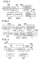
- a dividing section 100 of the speech parameter coding system thus receives Pth-order LSP parameters, divides them into a plurality of, for example, N, sets each including Kth-order LSP parameters (K ⁇ P) and sends each such Kth-order LSP parameters to a vector quantizer 110.
- the vector quantizer 110 has N codebooks 150-1 to 150-N constructed in advance corresponding to the dividing number at the dividing section 100 and each including Kth-order codevectors.
- the codebooks 150-1 to 150-N may be constructed such that they include the LSP parameters as they are, they may otherwise be constructed such that they may represent, making use of the characteristic that such LSP parameters have a high correlation between them at different order numbers, difference values between different spectrum parameters at different order numbers in order to represent them with higher efficiency.
- the codebooks 150-1 to 150-N are constructed by learning difference values between spectrum parameters at different order numbers for each predetermined order number as training signals. Such learning method is disclosed, for example, in Linde, Buzo and Gray, "An Algorithm for Vector Quantization Design” (reference 5).
- the vector quantizer 110 calculates a quantizing distortion for each Kth-order parameters in accordance with the following equation: where ⁇ i is the input ith-order LSP parameter, and ⁇ ' ij is the ith-order LSP parameter represented using the jth codevector.
- the vector quantizer 110 outputs M candidates of codevectors which minimize the equation (2) above for each Kth-order parameters in order of magnitude of distortion from the smaller one.
- An accumulated distortion calculating section 160 calculates an accumulated distortion E for all possible combinations of the M codevectors outputted for each Kth-order parameters in accordance with the following equation:
- a minimum discriminating section 170 finds a combination of candidates which minimizes the accumulated distortion E, and outputs the combination of codevectors then.
- the speech parameter coding system is different from the preceding speech parameter coding system of FIG. 1 in that the vector quantizing codebooks are connected in cascade connection at a plurality of stages and each of such stages receives an error signal between an input signal to the preceding stage and an output signal of the preceding stage and represents it in a codebook. Also, a codebook at at least one stage represents differences between spectrum parameters at different order numbers.
- the specific speech parameter coding system shown in FIG. 2 has two stages wherein spectrum parameters are not divided at. the first stage but they are divided into subframes for each Kth-order spectrum parameters.
- the speech parameter coding system receives Pth-order spectrum parameters, and the thus received Pth-order spectrum parameters are quantized by a first vector quantizer 200 using a first codebook 210 which is constructed by learning Pth-order spectrum parameters in advance.
- the first vector quantizer 200 calculates a distortion of the equation (2) given hereinabove using codevectors j of the codebook 210 and outputs M candidates in order of magnitude of distortion from the minimum.
- a subtractor 220 calculates, for each of the M candidates, an error signal of it from the input spectrum parameter and outputs the error signal to a second vector quantizer 230.
- the second vector quantizer 230 divides such error signals for each predetermined Kth-order parameters.
- the second vector quantizer 230 represents the error signals using second codebooks 240-1 to 240-N which represent differences between parameters at different order numbers for each Kth-order parameters.
- the equations (1) and (2) given hereinabove are used for the calculation of a distortion.
- the second vector quantizer 230 outputs M codevectors in order of magnitude of distortion of the equation (2) from the minimum one as candidates for each K parameters.
- An accumulated distortion calculating section 250 calculates accumulated distortions for all possible combinations of the M candidates outputted from the first stage and the candidates outputted from the second stage for each Kth-order parameters.
- a minimum discriminating section 260 finds a combination of candidates which minimizes an accumulated distortion and outputs a combination of codevectors then.
- learning of the first codebook is performed for Pth-order LSP parameters for the training using reference 5 mentioned hereinabove.
- learning of the second codebooks is performed for error signals using a similar method to that used in the speech parameter coding system described hereinabove with reference to FIG. 1.
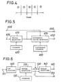
- the present speech parameter coding system divides an input speech signal into a plurality of frames of a predetermined time length (for example, 30 to 40 ms) and then divides the speech signal for each frame into a plurality of subframes (for example, 5 to 8 ms) shorter than the frame, whereafter it performs a well-known LPC analysis for at least one subframe in each frame to find a spectrum parameter.
- the present speech parameter coding system is hereinafter described as performing an LPC analysis, for example, for two subframes in each frame to find spectrum parameters. More particularly, an LPC analysis is performed, for example, for the second and fourth subframes among five subframes of a frame shown in FIG. 4.
- the thus found spectrum parameters are received by way of a pair of terminals 300 and 305 of the speech parameter coding system.
- the spectrum parameter of the subframe 2 is received by way of the terminal 300 while the spectrum parameter of the subframe 4 is received by way of the terminal 305.
- the spectrum parameters here are line spectrum pair (LSP) parameters for the convenience of description.
- LSP parameters can be calculated using the calculating method disclosed, for example, in reference 4 mentioned hereinabove.
- a vector quantizer 310 thus vector quantizes the input LSP parameters using a first codebook 320.
- the codebook 320 is constituted by learning in advance using a large amount of LSP parameter sequence for the training. Such learning method is disclosed, for example, in reference 5 mentioned hereinabove.
- the vector quantizer 310 outputs a codevector which minimizes the equation (4) above by way of a terminal 340 and further outputs the codevector to a predictive vector quantizer 330.
- the predictive vector quantizer 330 finds coefficient codevectors which minimize the equation (5) above, and outputs then as quantizing values for the spectrum parameters of the subframes by way of a terminal 350.
- the predictive coefficients of the coefficient codebook 360 can be constructed by learning the LSP parameter signal for the training using reference 5 mentioned hereinabove or the like so that the equation (5) above may be minimized.
- a non-linear prediction may be performed using non-linear processing.
- Two such methods are available.
- One of the two methods employs a non-linear predictive codebook as the coefficient codebook 360.
- a learning method of such non-linear predictive codebook is disclosed, for example, in S. Wang et al., "Performance of Non-Linear Prediction of Speech", Proc . ICSLP , pp.29-32, 1990 (reference 6).
- the other available method employs a prediction by a neural network instead of the predictive vector quantizer 330 and the coefficient codebook 360.
- the speech parameter coding system is similar to the speech parameter coding system shown in FIG. 3 in that it includes a vector quantizer 410 and a codebook 420 which are similar to the vector quantizer 310 and the codebook 320, respectively, but is different in that it includes a difference vector quantizer 470 and a difference codebook 480 in place of the predictive vector quantizer 330 and the coefficient codebook 360, respectively.
- the difference vector quantizer 470 performs vector quantization of the difference signal LSP e (i) using the difference codebook 480.
- the difference codebook 480 is constructed by learning the training signal of difference LSP parameters in advance using, for example, the method disclosed in reference 5. Then, the difference vector quantizer 470 selects a codevector which minimizes the quantizing distortion, and outputs the selected codevector by way of a terminal 450.
- the present speech parameter coding system divides an input speech signal received by way of a terminal 101 into a plurality of frames of a predetermined time length (for example, 30 to 40 ms) and performs, at an LSP analyzer 105, a well-known analysis to find spectrum parameters.
- the spectrum parameters may be line spectrum pair (LSP) parameters.
- LSP line spectrum pair
- a vector quantizer 110 vector quantizes the input LSP parameters using a codebook 120.
- the codebook 120 is constructed by learning in advance using a large amount of an LSP parameter sequence for the training.
- the vector quantizer 110 outputs a codevector, which minimizes the equation (7) above, to a subtractor 130.
- the vector quantizer 110 may select a single codevector which minimizes the equation (7) or select a plurality of codevectors which minimize the equation (7) in order of magnitude from the minimum one. Further, the vector quantizer 110 outputs an index or indices j representative of the selected codevector or codevectors to a scalar quantizer 140 and a terminal 155.
- the scalar quantizer 140 measures in advance for each order number i a distribution range of residual signals calculated by the subtractor 130 for each of predetermined M codevectors (M ⁇ 2 B , where B is a bit number of the codebook 120) determined at the codebook 120 in advance.
- M ⁇ 2 B a distribution range of residual signals calculated by the subtractor 130 for each of predetermined M codevectors (M ⁇ 2 B , where B is a bit number of the codebook 120) determined at the codebook 120 in advance.
- M ⁇ 2 B where B is a bit number of the codebook 120
- the modified speech parameter coding system is different from the speech parameter coding system of FIG. 6 in that it includes a different scalar quantizer 135 in place of the scalar quantizer 140 and additionally includes an accumulated distortion calculating section 165.
- the scalar quantizer 135 measures in advance an existing range of an output residual signal e(i) of the subtractor 130 for each order number i. Further, the residual signal e(i) is scalar quantized in the following manner.
- a quantizing range is determined as a maximum and a minimum of an existing range determined for each order number i, and the distance between the maximum and minimum is divided by a predetermined level number L.
- L 2 B .
- D SQM (i) [e(i) - e' M (i)] 2
- e' M (i) is the Mth candidate for a quantizing value outputted from the scalar quantizer 135.
- the existing range of LSP parameters is most overlapped among different order numbers. Further, the following expression always stands with regard to the order of LSP parameters: LSP(1) ⁇ LSP(2) ⁇ LSP(3) ⁇ ... ⁇ LSP(10) Making use of the characteristics, the quantizing range of the scalar quantizer 135 for the i-1th order is limited
- a maximum value of an existing range of LSP parameters at the i-1th order is greater than a vector-scalar quantizing value of an LSP parameter at the ith order, then the maximum value is set as a vector-scalar quantizing value at the ith order.
- a residual signal is thus scalar quantized with a predetermined number of bits for each order number by limiting a quantizing range using the method described just above.
- the accumulated distortion calculating section 165 calculates an accumulated distortion for each order number obtained by accumulation of quantizing distortions calculated for the individual candidates of scalar quantizing value in accordance with the following equation: Further, the accumulated distortion calculating section 165 calculates a candidate which minimizes an accumulated distortion for each order number, and outputs scalar quantizing values then by way of the output terminal 145.
- the modified speech parameter coding system is different from the speech parameter coding system of FIG. 7 in that it includes a different scalar quantizer 175 in place of the scalar quantizer 135.
- the scalar quantizer 175 measures in advance for each order number i a distributing range of a residual signal calculated by the subtractor 130 for each of M codevectors (M ⁇ 2 B , where B is a bit number of the codebook 120) determined in advance at the codebook 120.
- the scalar quantizer 175 changes over the distributing range using an index j received from the vector quantizer 110 and scalar quantizes the residual signal e(i) using a bit number determined in advance for each order number i. Further, when scalar quantization is performed for each order number of the residual signal, similarly as in the speech parameter coding system of FIG. 7, a plurality of candidates of quantizing value are determined for the ith order, and the quantizing range for scalar quantization for the i-1th order is limited using the candidates, whereafter quantizing distortions are accumulated for each of the candidates, and then a quantizing value which minimizes the accumulated distortion is found for each quantizing value order number and outputted by way of the terminal 145.
- the speech parameter coding system shown receives an input speech signal by way of an input terminal 500 and stores the speech signal for one frame (for example, 20 ms) into a buffer memory 510.
- An LPC analyzing circuit 530 performs a well-known LPC analysis from the speech signal of a frame to calculate a number of LSP parameters equal to a predetermined order number P as parameters which represent spectrum characteristics of the speech signal of the frame.
- An LSP quantizing circuit 540 quantizes the LSP parameters found for the frame with a predetermined quantizing number of bits and outputs a thus found code l K by way of an output terminal 550.
- FIG. 10 shows detailed construction of the LSP quantizing circuit 540.
- the LSP quantizing circuit 540 receives Pth-order LSP parameters of a frame by way of an input terminal 600.
- the input Pth-order LSP parameters are divided for each Kth-order LSP parameters (K ⁇ P) by a dividing circuit 610, and each such Kth-order LSP parameters are outputted to a vector quantizing circuit 620.
- the vector quantizing circuit 620 constructs in advance N codebooks 650-1 to 650-N corresponding to the dividing number N at the dividing circuit 610 for each Kth-order LSP parameters.
- the codebooks 650-1 to 650-N are each constituted from a number of codevectors depending upon a predetermined bit number.
- the codebooks 650-1 to 650-N are constructed such that, as described hereinabove, they may represent difference values between LSP parameters at different order numbers.
- the vector quantizing circuit 620 calculates a quantizing distortion for each Kth-order LSP parameters beginning with the first order LSP parameter and outputs M candidates of codevector in order of magnitude of quantizing distortion from the minimum for each Kth-order LSP parameters.
- LSP parameters are represented, for the next Kth-order LSP parameters, using the codebook 650-2 in accordance with the equation (1) given hereinabove using each of the M candidates as an initial value, and then quantizing distortions are calculated in accordance with the equation (2) given hereinabove, whereafter M candidates are found in order of magnitude of quantizing distortion from the minimum one. After then, such processing will be repeated by a number of times equal to the dividing number N.
- An accumulated distortion calculating circuit 660 calculates accumulated distortions for all possible combinations of the M codevectors outputted for each Kth-order LSP parameters in accordance with the equation (3) given hereinabove.
- a minimum discriminating circuit 670 finds a combination of candidates which minimizes the accumulated distortion, and outputs a combination of indices of the codevectors then by way of a terminal 680.
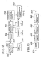
- FIG. 11 there is shown a modification to the speech parameter coding system shown in FIG. 9 in that it includes a different LSP quantizing circuit 700 in place of the LSP quantizing circuit 540.
- FIG. 12 shows details of the LSP quantizing circuit 700.
- the LSP quantizing circuit 700 receives Pth-order spectrum parameters by way of a terminal 705.
- the input Pth-order spectrum parameters are quantized by a first vector quantizing circuit 706 using a first codebook 710 which is constructed by learning in advance.
- the first vector quantizing circuit 706 calculates a distortion of the equation (2) given hereinabove for each of codevectors of the codebook 710 and outputs M candidates in order of magnitude of distortion from the minimum one.
- a subtractor 707 calculates an error signal between each of the M candidates and the input spectrum parameter and outputs it to a dividing circuit 702.
- the dividing circuit 702 calculates the Pth-order error signals for each predetermined Kth-order spectrum parameters (K ⁇ P).
- a second vector quantizing circuit 715 vector quantizes the error signals for each Kth-order spectrum parameters using second codebooks 720-1 to 720-N which are constructed such that they may represent differences between spectrum parameters at different order numbers for each Kth-order spectrum parameters.
- the equations (1) and (2) given hereinabove are used for the calculation of distortions.
- the second vector quantizing circuit 715 outputs, for each Kth-order spectrum parameters, M codevectors in order of magnitude of distortion of the equation (2) from the minimum one as candidates.
- Detailed operation of the second vector quantizing circuit 715 is similar to that of the vector quantizing circuit 620 of FIG. 10.
- An accumulated distortion calculating circuit 750 accumulates quantizing distortions for all possible combinations of the M candidates outputted from the first vector quantizing circuit 706 and the candidates outputted from the second vector quantizing circuit 715 for each Kth-order spectrum parameters to calculate accumulated distortions.
- a minimum discriminating circuit 760 finds a combination of candidates which minimizes the accumulated distortion, and outputs a combination of indices representative of codevectors then by way of a terminal 770.
- the speech parameter coding system receives an input speech signal by way of an input terminal 800 and stores the speech signal for one frame (for example, 30 to 40 ms) into a buffer memory 810.
- a subframe dividing circuit 820 divides the speech signal of each frame into a predetermined plurality of subframes (for example, 5 to 8 ms).
- An LPC analyzing circuit 830 performs a well-known LPC analysis from the speech signal of the frame to calculate a number of LSP parameters equal to a predetermined order number P as parameters which represent spectrum characteristics of the speech signal at predetermined subframe positions (for example, the second and fourth positions in FIG. 4). Details of such calculation are disclosed, for example, in reference 4 mentioned hereinabove.
- An LSP quantizing circuit 840 quantizes the LSP parameters calculated for the frame with a predetermined number of quantizing bits and outputs the thus calculated codes l K by way of an output terminal 850.
- the following description proceeds on the assumption that vector quantization of the dividing type is performed as vector quantization which can be realized with a small amount of calculations and a small memory capacity by the LSP quantizing circuit 840.
- FIG. 14 shows detailed construction of the LSP quantizing circuit 840.
- the LSP quantizing circuit 840 receives LSP parameters of a frame by way of an input terminal 900.
- a dividing circuit 910 receives such Pth-order input LSP parameters and divides them for each Kth-order LSP parameters (K ⁇ P) and then outputs such LSP parameters for each Kth-order LSP parameters to a vector quantizing circuit 920.
- the vector quantizing circuit 920 constructs in advance for each Kth-order LSP parameters N codebooks 950-1 to 950-N corresponding to the dividing number N at the dividing circuit 910.
- the codebooks 950-1 to 950-N are each constituted from a number of codevectors (2 L ) depending upon a predetermined bit number L. Further, the codebooks 950-1 to 950-N are constructed such that they may represent difference values between LSP parameters at different order numbers.
- the codebooks 950-1 to 950-N are constructed by learning difference values between LSP parameters at different order numbers as training signals for spectrum parameters for a predetermined order number. Such learning method is disclosed, for example, in reference 5 mentioned hereinabove.
- the vector quantizing circuit 920 further calculates a quantizing distortion for each Kth-order LSP parameters in accordance with the following equation: where ⁇ ; is the input ith LSP parameter, and ⁇ ' ij is the ith LSP parameter represented using the jth codevector of the ith codebook.
- the vector quantizing circuit 920 calculates quantizing distortions for each Kth-order LSP parameters beginning with the first order LSP parameter in accordance with the equation (5) given hereinabove and outputs M candidates of codevector in order of magnitude of quantizing distortion from the minimum one for each Kth-order LSP parameters.
- the LSP parameters are represented, for the next Kth-order LSP parameters, using the codebook 950-2 in accordance with the equation (4) given hereinabove using each of the M candidates as an initial value, and quantizing distortions are found in accordance with the equation (5) given hereinabove, whereafter M candidates are found in order of magnitude of quantizing distortion from the minimum one. After then, such processing will be repeated by a number of times equal to the dividing number N described hereinabove.
- An accumulated distortion calculating section 960 calculates accumulated distortions for all possible combinations of the M codevectors outputted for each Kth-order LSP parameters in accordance with the following equation:
- a minimum discriminating circuit 970 finds a combination of candidates which minimizes the accumulated distortion E, and outputs a combination of codevectors then.
- a predictive vector quantizing circuit 990 predicts an LSP parameter sequence of the other subframe received by way of a terminal 905 using the output codevector of the minimum discriminating circuit 970 and a coefficient codebook 980, and calculates predictive quantizing distortions in accordance with the equation (5) given hereinabove. Then, the predictive vector quantizing circuit 990 finds a coefficient codevector which minimizes the equation (5), and outputs the coefficient codevector and the output codevector of the minimum discriminating circuit 970 as quantized values of spectrum parameters of the two subframes.
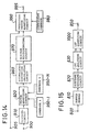
- FIG. 15 there is shown a modification to the speech parameter coding system of FIG. 13 in that it includes a different LSP quantizing circuit 1000 in place of the LSP quantizing circuit 840.
- the LSP quantizing circuit 1000 is a modification to the LSP quantizing circuit 840 shown in FIG. 14 in that it includes a difference vector quantizing circuit 1010 and a difference codebook 1020 in place of the predictive vector quantizing circuit 990 and the coefficient codebook 980, respectively.
- the difference vector quantizing circuit 1010 calculates difference signals between an LSP parameter sequence of the other subframe inputted by way of the terminal 905 and an output of the minimum discriminating circuit 970 in accordance with the equation (6) given hereinabove, and then performs vector quantization of the difference signals using the difference codebook 1020.
- the difference vector quantizing circuit 1010 outputs a codevector which minimizes the quantizing distortion and the output codevector of the minimum discriminating circuit 970.
- the speech parameter coding system receives an input speech signal by way of an input terminal 101 and stores the input speech signal for one frame (for example, 40 ms) into a buffer memory 103.
- An LSP analyzing circuit 107 performs a well-known LPC analysis to find LSP coefficients as spectrum parameters.
- a vector quantizing circuit 112 vector quantizes the input LSP parameters using a codebook 120.
- the codebook 120 is constructed by learning in advance using a large amount of LSP parameter sequence for the training. While various distortion scales in searching for a codevector are known, here a squared distance between LSP parameters is used.
- the vector quantizing circuit 112 finds a codevector which minimizes the equation (7) given hereinabove, and outputs it to a subtracting circuit 130.
- the vector quantizing circuit 112 may select a single codevector which minimizes the equation (7) or select a plurality of codevectors which minimize the equation (7) in order of magnitude from the minimum one. Further, the vector quantizing circuit 112 outputs an index j representative of the selected codevector to a scalar quantizing circuit 142 and a terminal 155.
- the subtracting circuit 130 subtracts the value of the selected codevector from the input LSP parameters to find residual signals e(i) in accordance with the equation (8) given hereinabove and outputs them to the scalar quantizing circuit 142.
- the scalar quantizing circuit 142 measures in advance for each order number i a distribution range of residual signals calculated by the subtracting circuit 130 for each of M codevectors (M ⁇ 2 B , where B is a bit number of the codebook 120) determined at the codebook 120 in advance, and stores such distribution ranges into a quantizing range table 160. Further, the scalar quantizing circuit 142 changes over the distribution range of the quantizing range table 160 using the index j received from the vector quantizing circuit 112 and scalar quantizes the residual signals e(i) using a bit number determined in advance for each order number i. The results of such scalar quantization are outputted to a terminal 145.
- FIG. 18 there is shown a modification to the speech parameter coding apparatus of FIG. 17 in that it includes a different scalar quantizing circuit 143 in place of the scalar quantizing circuit 142 and additionally includes an accumulated distortion calculating circuit 165 and a discriminating circuit 185.
- the scalar quantizing circuit 143 measures in advance for each order number i an existing range of output residual signals e(i) of the subtracting circuit 130 and stores such existing ranges into the quantizing range table 160. As described hereinabove, the scalar quantizing circuit 143 calculates a quantizing distortion for each of quantizing values for the scalar quantization, finds M candidates (here, M ⁇ L) in order of magnitude of quantizing distortion from the minimum one, and outputs quantizing distortion values for the individual candidates to the accumulated distortion calculating circuit 165. Then, the scalar quantizing circuit 143 limits the quantizing ranges using the values of the candidates as described hereinabove and scalar quantizes the residual signals for each order number with a predetermined number of bits.
- M candidates here, M ⁇ L
- the accumulated distortion calculating circuit 165 calculates an accumulated distortion wherein the quantizing distortions found for each of the candidates of scalar quantizing value are accumulated for each order number, in accordance with the equation (11) given hereinabove.
- the discriminating circuit 185 finds a candidate which minimizes the accumulated distortion for each order number, and outputs a scalar quantizing value then by way of the terminal 145.
- FIG. 19 there is shown a modification to the modified speech parameter coding apparatus of FIG. 18 in that it includes a different scalar quantizing circuit 195 in place of the scalar quantizing circuit 143.
- the scalar quantizing circuit 195 measures in advance for each order number i a distribution range of residual signals calculated by the subtractor 130 for each of M codevectors (M ⁇ 2 B , where B is a bit number of the codebook 120) determined at the codebook 120 in advance, and stores such distribution ranges into the quantizing range table 160. Further, the scalar quantizing circuit 193 changes over the quantizing range using the index j received from the vector quantizing circuit 112 and scalar quantizes the residual signals e(i) using a bit number determined in advance for each order number i.
- the scalar quantizing circuit 195 calculates, when scalar quantization is to be performed for each order number of the residual signals, a plurality of candidates of quantizing value for the ith order, limits the quantizing range of scalar quantization for the i-1th order using the candidates and performs scalar quantization of each of the candidates, similarly as described hereinabove.
- the accumulated distortion calculating circuit 165 accumulates a quantizing distortion for each of the candidates in the quantizing range for each order number.
- the discriminating circuit 185 finds a quantizing value which minimizes the accumulated distortion for each order number, and outputs such quantizing values by way of the terminal 145.
- an LSP parameter is used as a spectrum parameter of a speech signal in the speech parameter coding systems described above
- any other known parameter such as, for example, a PARCOR, LAR or cepstrum parameter may be used alternatively.
- any other known distance scale than such squared distance between LSP parameters represented by the equation (2) given hereinabove may be used alternatively.
- a perceptual weighted squared distance is known as one of such distance scales and disclosed, for example, in Honda, "Vector Quantization of LPC Parameters Using Weighted Logarithmic Spectral Distortion Scale", Lecture Thesis Collection of Acoustical Society , pp.195-196, October, 1990 (reference 8).
- Pth-order parameters are divided uniformly for each Kth-order parameters by the dividing circuit, they may otherwise be divided non-uniformly.
- a candidate need not be found by the vector quantizers at all stages or at all divisions and alternatively, a plurality of candidates may be found by vector quantizers at a predetermined number of stages.
- the learning method of a codebook representative of differences of spectrum parameters when vector quantization is performed for each Kth-order parameters may be any other learning method than that described hereinabove.
- learning may be performed coding a training signal with a codebook ⁇ ' 1 so that an error power given by the following equation or a weighted error power may be minimized:
- an optimum combination of candidates may be selected using any other well-known high speech calculating method such as, for example, a dynamic programming method.
- any other well-known vector quantizer of a different construction such as of the tree search type, lattice type or multi-stage type may alternatively be used in order to reduce a total amount of calculation required for the searching for a codevector. Details of such calculation amount reducing techniques are disclosed, for example, in Gray, "Vector Quantization", IEEE ASSP Magazine , pp.4-29, 1984 (reference 9).
- codebooks 1 to N in the speech parameter coding systems of FIGS. 9 and 11 represent differences between LSP parameters at different order numbers, they may otherwise represent LSP parameters directly as they are.
- the speech parameter coding system of FIG. 13 or 15 may be modified such that the minimum discriminating circuit 970 of the LSP quantizing circuit 840 or 1000 is displaced to a location subsequent to the predictive quantizing circuit 990 or difference vector quantizing circuit 1010 such that predictive vector quantization or difference vector quantization is performed for each of candidates outputted from the vector quantizing circuit 920, and then an accumulated distortion for each candidate found by the accumulated distortion calculating circuit 960 and a quantizing distortion caused by such predictive vector quantization or difference vector quantization are added to find a total distortion, whereafter a set of codevectors which minimize the total distortion and a predictive codevector or a difference codevector are selected by the minimum discriminating circuit 970. While such modification increases a total amount of calculation, it will result in improvement in characteristic.
- any other well-known method may be employed for the vector quantization by the vector quantizing circuit 920.
- multi-stage vector quantization wherein a plurality of codebooks are connected in cascade connection at a plurality of stages and the divisional vector quantization described hereinabove may be combined.
- vector quantizing circuit 920 finds M candidates by vector quantization for each division, this will result in exponential increase of the number of candidates for all order numbers or for all stages.
- vector quantization for three divisions involves a total of M 2 candidates.
- the accumulated distortions are trimmed to select a predetermined fixed number of (for example, M) candidates for each stage in order of magnitude of accumulated distortion from the minimum one, then the total number of candidates is M as a whole, and consequently, the number of candidates is prevented from increasing exponentially.
- the amount of calculation can be reduced remarkably comparing with the method employed in the speech parameter coding system, but the performance is deteriorated a little.
- a candidate need not be found at all divisions and alternatively, a plurality of candidates may be found by vector quantizers at a predetermined division or divisions.
- the learning method of a codebook representative of differences of spectrum parameters when vector quantization is performed for each Kth-order parameters may be any other learning method than that described hereinabove.
- learning may be performed coding a training signal with a codebook ⁇ ' i in accordance with a closed loop method so that an error power given by the following equation or a weighted error power may be minimized:
- learning of such codebooks may be repeated alternately using a training signal in order to perform optimal learning.
- the dividing circuit 910 of the speech parameter coding system of FIG. 15 divides LSP parameters uniformly for each Kth-order parameters, the LSP parameters may otherwise be divided non-uniformly.
- an optimum combination of candidates may be selected using any other well-known high speed calculating method such as, for example, a dynamic programming method.
- a predictive coefficient codebook is produced for each subframe in the speech parameter coding system of FIG. 13, alternatively a matrix codebook wherein a codebook is produced collectively for a plurality of subframes may be employed. Production of such matrix codebook is disclosed, for example, in C. Tsao et al., "Matrix Quantizer Design for LPC Speech Using the Generalized Lloyd Algorithm", IEEE Trans . ASSP , pp.537-545, 1985 (reference 10). With the construction which employs a matrix codebook, since a plurality of subframes are represented collectively in codevectors, the number of bits required for predictive coefficient codevector transmission can be decreased.
- the speech parameter coding system of FIG. 15 may otherwise use a value other than 1 for B of the equation (6) given hereinabove. Further, such B may be included in a codebook such that an optimum coefficient may be selected from within the codebook.
- the distance scale in vector quantization or the distance scale in scalar quantization may be any other suitable well-known distance scale than the squared distance such as, for example, a weighted distance scale, a cepstrum distance scale or a melcepstrum distance scale.
- spectrum parameters are calculated for a speech signal for a frame
- a frame may be divided into a plurality of shorter subframes and spectrum parameters may be calculated for a predetermined one or ones of such subframes to effect vector-scalar quantization of them.
- any of the speech parameter coding systems of FIG. 17 to 19 may be modified such that, when a predetermined order number of quantizing ranges for scalar quantization are determined for a predetermined number of codevectors for vector quantization, a quantizing range may be measured for each of all codevectors (2 B ) or for each of a smaller number of codevectors. Or else, different quantizing ranges may be determined for each codevector, or a common quantizing range may be determined for several codevectors. Further, when a quantizing range is measured, such measurement may be performed for spectrum parameters of all orders, or else, such measurement may be performed for a smaller order number of spectrum parameters while a predetermined quantizing range or ranges are provided for the other order number spectrum parameters.
- a frame may be divided into a plurality of shorter subframes such that the present invention is applied to one of the subframes to quantize a spectrum parameter while at least one of the other subframes is represented using quantized values of spectrum parameters of the frame, quantized values of spectrum parameters of a frame or frames in the past and interpolation coefficients or an interpolation coefficient codebook.
Landscapes
- Engineering & Computer Science (AREA)
- Physics & Mathematics (AREA)
- Audiology, Speech & Language Pathology (AREA)
- Computational Linguistics (AREA)
- Signal Processing (AREA)
- Health & Medical Sciences (AREA)
- Human Computer Interaction (AREA)
- Acoustics & Sound (AREA)
- Multimedia (AREA)
- Spectroscopy & Molecular Physics (AREA)
- Theoretical Computer Science (AREA)
- Transmission Systems Not Characterized By The Medium Used For Transmission (AREA)
- Compression, Expansion, Code Conversion, And Decoders (AREA)
Claims (3)
- Dispositif de codage de paramètres vocaux, comprenant :des moyens (101) pour diviser un signal vocal d'entrée en une pluralité de trames ;des moyens (105) pour trouver un numéro d'ordre prédéterminé de paramètres spectraux à partir du signal vocal ;des moyens (110) pour une quantification vectorielle des paramètres spectraux ; .des moyens (140) pour une quantification scalaire de signaux de différence entre les paramètres spectraux et les valeurs quantifiées vectoriellement ; etdes moyens pour déterminer un numéro d'ordre prédéterminé d'intervalles de quantification pour la quantification scalaire pour chacun d'un nombre prédéterminé de vecteurs de code desdits moyens de quantification vectorielle, afin que lesdits moyens de quantification scalaire (140) effectuent une quantification scalaire dans les intervalles de quantification.
- Dispositif de codage de paramètres vocaux, comprenant :des moyens (101) pour diviser un signal vocal d'entrée en une pluralité de trames ;des moyens (105) pour trouver un numéro d'ordre prédéterminé de paramètres spectraux à partir du signal vocal ;des moyens (112) pour une quantification vectorielle des paramètres spectraux ;des moyens (195) pour une quantification scalaire de signaux de différence entre les paramètres spectraux et les valeurs quantifiées vectoriellement ;des moyens pour produire une pluralité de candidats de valeur de. quantification pour chaque numéro d'ordre des paramètres spectraux auxdits moyens de quantification scalaire ;des moyens pour modifier, en utilisant chacun des candidats, un intervalle de quantification d'un paramètre spectral adjacent ; etdes moyens (165) pour cumuler un numéro d'ordre prédéterminé de distorsions de quantification par les valeurs quantifiées et produire une séquence de valeurs quantifiées qui minimise la distorsion cumulée.
- Dispositif de codage de paramètres vocaux selon la revendication 1, comprenant en outre :des moyens pour produire une pluralité de candidats de valeur de quantification pour chaque numéro d'ordre des paramètres spectraux pour la quantification scalaire ;des moyens pour modifier, en utilisant chacun des candidats, un intervalle de quantification d'un paramètre spectral adjacent ; etdes moyens pour cumuler un numéro d'ordre prédéterminé de distorsions de quantification par les valeurs de quantification et produire une séquence de valeurs quantifiées qui minimise la distorsion cumulée.
Applications Claiming Priority (7)
| Application Number | Priority Date | Filing Date | Title |
|---|---|---|---|
| JP10326791 | 1991-02-26 | ||
| JP103267/91 | 1991-02-26 | ||
| JP10326791 | 1991-02-26 | ||
| JP26192591 | 1991-10-09 | ||
| JP261925/91 | 1991-10-09 | ||
| JP26192591A JP3151874B2 (ja) | 1991-02-26 | 1991-10-09 | 音声パラメータ符号化方式および装置 |
| EP92103179A EP0504627B1 (fr) | 1991-02-26 | 1992-02-25 | Méthode et dispositif de codage de paramètres de voix |
Related Parent Applications (1)
| Application Number | Title | Priority Date | Filing Date |
|---|---|---|---|
| EP92103179A Division EP0504627B1 (fr) | 1991-02-26 | 1992-02-25 | Méthode et dispositif de codage de paramètres de voix |
Publications (3)
| Publication Number | Publication Date |
|---|---|
| EP0910064A2 EP0910064A2 (fr) | 1999-04-21 |
| EP0910064A3 EP0910064A3 (fr) | 1999-06-16 |
| EP0910064B1 true EP0910064B1 (fr) | 2002-12-18 |
Family
ID=26443908
Family Applications (2)
| Application Number | Title | Priority Date | Filing Date |
|---|---|---|---|
| EP98124814A Expired - Lifetime EP0910064B1 (fr) | 1991-02-26 | 1992-02-25 | Dispositif de codage du paramêtre de la parole |
| EP98124813A Expired - Lifetime EP0910063B1 (fr) | 1991-02-26 | 1992-02-25 | Procédé de codage de parole |
Family Applications After (1)
| Application Number | Title | Priority Date | Filing Date |
|---|---|---|---|
| EP98124813A Expired - Lifetime EP0910063B1 (fr) | 1991-02-26 | 1992-02-25 | Procédé de codage de parole |
Country Status (2)
| Country | Link |
|---|---|
| EP (2) | EP0910064B1 (fr) |
| DE (3) | DE69232887T2 (fr) |
Families Citing this family (1)
| Publication number | Priority date | Publication date | Assignee | Title |
|---|---|---|---|---|
| GB2490879B (en) * | 2011-05-12 | 2018-12-26 | Qualcomm Technologies Int Ltd | Hybrid coded audio data streaming apparatus and method |
Family Cites Families (7)
| Publication number | Priority date | Publication date | Assignee | Title |
|---|---|---|---|---|
| CA1323934C (fr) * | 1986-04-15 | 1993-11-02 | Tetsu Taguchi | Appareil de traitement de paroles |
| GB2210236B (en) * | 1987-09-24 | 1991-12-18 | Newbridge Networks Corp | Speech processing system |
| US4852179A (en) * | 1987-10-05 | 1989-07-25 | Motorola, Inc. | Variable frame rate, fixed bit rate vocoding method |
| US5194950A (en) * | 1988-02-29 | 1993-03-16 | Mitsubishi Denki Kabushiki Kaisha | Vector quantizer |
| IT1224453B (it) * | 1988-09-28 | 1990-10-04 | Sip | Procedimento e dispositivo per la codifica decodifica di segnali vocali con l'impiego di un eccitazione a impulsi multipli |
| IT1232084B (it) * | 1989-05-03 | 1992-01-23 | Cselt Centro Studi Lab Telecom | Sistema di codifica per segnali audio a banda allargata |
| DE69133296T2 (de) * | 1990-02-22 | 2004-01-29 | Nec Corp | Sprachcodierer |
-
1992
- 1992-02-25 DE DE69232887T patent/DE69232887T2/de not_active Expired - Lifetime
- 1992-02-25 DE DE69232879T patent/DE69232879T2/de not_active Expired - Lifetime
- 1992-02-25 DE DE69229974T patent/DE69229974T2/de not_active Expired - Lifetime
- 1992-02-25 EP EP98124814A patent/EP0910064B1/fr not_active Expired - Lifetime
- 1992-02-25 EP EP98124813A patent/EP0910063B1/fr not_active Expired - Lifetime
Also Published As
| Publication number | Publication date |
|---|---|
| DE69232879T2 (de) | 2003-05-08 |
| DE69232887D1 (de) | 2003-02-06 |
| DE69229974T2 (de) | 2000-07-20 |
| EP0910063A3 (fr) | 1999-06-09 |
| EP0910063A2 (fr) | 1999-04-21 |
| EP0910063B1 (fr) | 2003-01-02 |
| DE69229974D1 (de) | 1999-10-21 |
| DE69232887T2 (de) | 2003-06-05 |
| EP0910064A2 (fr) | 1999-04-21 |
| EP0910064A3 (fr) | 1999-06-16 |
| DE69232879D1 (de) | 2003-01-30 |
Similar Documents
| Publication | Publication Date | Title |
|---|---|---|
| EP0504627B1 (fr) | Méthode et dispositif de codage de paramètres de voix | |
| EP0443548B1 (fr) | Codeur de parole | |
| US5271089A (en) | Speech parameter encoding method capable of transmitting a spectrum parameter at a reduced number of bits | |
| US5675702A (en) | Multi-segment vector quantizer for a speech coder suitable for use in a radiotelephone | |
| US6122608A (en) | Method for switched-predictive quantization | |
| KR100872538B1 (ko) | Lpc 파라미터의 벡터 양자화 장치, lpc 파라미터복호화 장치, lpc 계수의 복호화 장치, 기록 매체,음성 부호화 장치, 음성 복호화 장치, 음성 신호 송신장치, 및 음성 신호 수신 장치 | |
| JP3114197B2 (ja) | 音声パラメータ符号化方法 | |
| US6023672A (en) | Speech coder | |
| EP1093116A1 (fr) | Boucle de recherche basée sur l'autocorrélation pour un codeur de parole de type CELP | |
| CA2061830C (fr) | Systeme de codage de paroles | |
| EP1162604B1 (fr) | Codeur de la parole de haute qualité à faible débit binaire | |
| JP2800618B2 (ja) | 音声パラメータ符号化方式 | |
| EP0899720A2 (fr) | Quantisation des coefficients de prédiction linéaire | |
| US6236961B1 (en) | Speech signal coder | |
| EP0910064B1 (fr) | Dispositif de codage du paramêtre de la parole | |
| EP0483882B1 (fr) | Méthode de codage de paramètres de parole permettant de transmettre un paramètre spectral sur un nombre de bits de réduits | |
| US5978758A (en) | Vector quantizer with first quantization using input and base vectors and second quantization using input vector and first quantization output | |
| EP0755047B1 (fr) | Procédé de codage d'un paramètre de parole capable de transmettre à débit réduit un paramètre spectral | |
| JP3230380B2 (ja) | 音声符号化装置 |
Legal Events
| Date | Code | Title | Description |
|---|---|---|---|
| PUAI | Public reference made under article 153(3) epc to a published international application that has entered the european phase |
Free format text: ORIGINAL CODE: 0009012 |
|
| AC | Divisional application: reference to earlier application |
Ref document number: 504627 Country of ref document: EP |
|
| AK | Designated contracting states |
Kind code of ref document: A2 Designated state(s): DE FR GB |
|
| PUAL | Search report despatched |
Free format text: ORIGINAL CODE: 0009013 |
|
| AK | Designated contracting states |
Kind code of ref document: A3 Designated state(s): DE FR GB |
|
| 17P | Request for examination filed |
Effective date: 19990506 |
|
| 17Q | First examination report despatched |
Effective date: 20010320 |
|
| RIC1 | Information provided on ipc code assigned before grant |
Free format text: 7G 10L 19/00 A |
|
| GRAG | Despatch of communication of intention to grant |
Free format text: ORIGINAL CODE: EPIDOS AGRA |
|
| RIC1 | Information provided on ipc code assigned before grant |
Free format text: 7G 10L 19/00 A |
|
| GRAG | Despatch of communication of intention to grant |
Free format text: ORIGINAL CODE: EPIDOS AGRA |
|
| GRAG | Despatch of communication of intention to grant |
Free format text: ORIGINAL CODE: EPIDOS AGRA |
|
| GRAH | Despatch of communication of intention to grant a patent |
Free format text: ORIGINAL CODE: EPIDOS IGRA |
|
| RTI1 | Title (correction) |
Free format text: SPEECH PARAMETER CODING APPARATUS |
|
| GRAH | Despatch of communication of intention to grant a patent |
Free format text: ORIGINAL CODE: EPIDOS IGRA |
|
| GRAA | (expected) grant |
Free format text: ORIGINAL CODE: 0009210 |
|
| AC | Divisional application: reference to earlier application |
Ref document number: 504627 Country of ref document: EP |
|
| AK | Designated contracting states |
Kind code of ref document: B1 Designated state(s): DE FR GB |
|
| REG | Reference to a national code |
Ref country code: GB Ref legal event code: FG4D |
|
| REF | Corresponds to: |
Country of ref document: DE Kind code of ref document: P Ref document number: 69232879 Date of ref document: 20030130 |
|
| ET | Fr: translation filed | ||
| PLBE | No opposition filed within time limit |
Free format text: ORIGINAL CODE: 0009261 |
|
| STAA | Information on the status of an ep patent application or granted ep patent |
Free format text: STATUS: NO OPPOSITION FILED WITHIN TIME LIMIT |
|
| 26N | No opposition filed |
Effective date: 20030919 |
|
| PGFP | Annual fee paid to national office [announced via postgrant information from national office to epo] |
Ref country code: DE Payment date: 20110223 Year of fee payment: 20 Ref country code: FR Payment date: 20110218 Year of fee payment: 20 |
|
| PGFP | Annual fee paid to national office [announced via postgrant information from national office to epo] |
Ref country code: GB Payment date: 20110223 Year of fee payment: 20 |
|
| REG | Reference to a national code |
Ref country code: DE Ref legal event code: R071 Ref document number: 69232879 Country of ref document: DE |
|
| REG | Reference to a national code |
Ref country code: DE Ref legal event code: R071 Ref document number: 69232879 Country of ref document: DE |
|
| REG | Reference to a national code |
Ref country code: GB Ref legal event code: PE20 Expiry date: 20120224 |
|
| PG25 | Lapsed in a contracting state [announced via postgrant information from national office to epo] |
Ref country code: DE Free format text: LAPSE BECAUSE OF EXPIRATION OF PROTECTION Effective date: 20120226 |
|
| PG25 | Lapsed in a contracting state [announced via postgrant information from national office to epo] |
Ref country code: GB Free format text: LAPSE BECAUSE OF EXPIRATION OF PROTECTION Effective date: 20120224 |