FIELD OF THE INVENTION
The present invention relates to a silver halide
emulsion improved in sensitivity, pressure resistance and
processability.
BACKGROUND OF THE INVENTION
Recently, demand for enhanced sensitivity and image
quality of silver halide light sensitive photographic
materials has become stronger. In addition, requirements for
enhanced photographic performance which is more resistant
under external factors such as pressure, processing
fluctuations and storage at high temperature and/or high
humidity, have been increased.
In response to such requirements, an attempt to enhance
photographic performance of a silver halide emulsion by
introducing dislocation lines into silver halide grains was
made. JP-A 63-220238 and 1-102547 (herein, the term, JP-A
means an unexamined published Japanese Patent Application)
disclose techniques for improving photographic characteristics
through the introduction of dislocation lines. However, as can
be seen from the fact that the disclosure of the techniques
described above was followed by disclosure of a number of
techniques regarding the dislocation lines, further improved
technique of dislocation line introduction is still required.
JP-A 3-175440 discloses a technique of allowing
dislocation lines to be concentrated at the edge of tabular
grains to improve sensitivity and reciprocity law failure
characteristics. JP-A 6-27564 discloses a technique of
restricting dislocation lines to fringe portions of tabular
grains to improve sensitivity and pressure resistance.
Noticeable results of the prior art include improvements
of photographic performance by restricting the position of
dislocation lines to a specific site. It is supposed by the
inventors of the present invention that restriction of
dislocation lines to the specific position also limits the
position of deteriorating factors produced along with the
dislocation lines and these techniques are restrained so as to
not produce influences counteracting improvement effects due
to the dislocation lines.
The inventors further noted that introduction of iodide
ions accompanied formation of a high iodide layer within the
grain. As disclosed in JP-A 6-27564, a means for introducing
dislocation lines is to introduce iodide ions, forming a gap
or misfit of the crystal lattice.
In a technique regarding an iodide content continuously
varying layer disclosed in JP-A 5-53232, 9-138473 and 9-211759,
improvement of photographic performance such as sensitivity
and pressure resistance were accomplished by reducing the gap
and/or misfit of the crystal lattice. However, the gap and/or
misfit of the crystal lattice resulting from introducing the
dislocation in the prior art, i.e. the presence of a layer in
which the iodide content is steeply varied, resulted in
possibility of counteracting the effects of the iodide content
continuously varying layer described above.
It has not been clarified from the prior study whether
the crystal lattice gap/misfit as in the prior art is
essentially dispensable or not to introduce the dislocation
lines. It is supposed that an excessively high iodide layer
may be formed.
The presence of the high iodide containing layer with
the grain is contemplated to be related to deterioration of
photographic performance, such as sensitivity loss due to
closely localized lattice defects, lowered pressure resistance
and deterioration in processability due to iodide ions
released at development.
Supposing that when dislocation lines are formed
according to the prior art, a high iodide layer is also
concurrently formed, leading to deterioration in photographic
performance due to the high iodide layer as well as improved
photographic performance due to the dislocation lines, so that
effects of the dislocation lines can not be sufficiently
displayed, the inventors of the present invention made further
study.
FR-A-2 516 264 discloses a
photographic product consisting of a support and at least one
photosensible emulsion layer formed from a dispersing medium
and tabular grains of silver iodobromide, characterized in that
at least 50 % of the total projected surface of the silver
iodobromide grains is formed of tabular grains having two
principle surfaces parallelly opposed to each other, with a
thickness of at least of 0.5 µm, a diameter of at least 0.6 µm,
the grain diameter being defined as the diameter of a circle,
the surface of which equals the grain projected surface, and a
mean form index, defined as the relation of the grain diameter
to its thickness, which is higher than 8:1, at least one part
of these silver iodobromide tabular grains comprising a central
area located between their main surfaces, containing a lower
proportion of iodine than at least one peripheral portion,
which is also located between the principal surfaces.
SUMMARY OF THE INVENTION
Accordingly, it is an object of the present invention to
provide a silver halide emulsion with enhanced sensitivity and
superior pressure resistance and improved processability.
The above object of the invention can be accomplished by
the following constitution:
BRIEF DESCRIPTION OF THE DRAWINGS
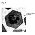
Fig. 1 is an electronmicrograph of a silver halide grain
having a silver iodide border.
Figs. 2 and 3 illustrate variation of the silver iodide
content within a silver halide grain in the direction from the
center to the edge.
DETAILED DESCRIPTION OF THE INVENTION
Effects of the present invention are supposed to be
attributable mainly to reduction of a high iodide containing
layer formed at the time of introducing dislocation lines
without lowering the dislocation line introducing efficiency
and also to its synergistic effect with grain monodispersity,
shallow electron trapping centers and reduction sensitization.
Thus, the essential of the present invention is that the
position of photographic performance deteriorating factors
which are concurrently produced with the dislocation lines, is
not limited, as in the prior art, but the photographic
performance deteriorating factors themselves are reduced.
In the present invention, dislocation lines are closely
introduced and abrupt variation in silver iodide content
produced when introducing the dislocation lines is prevented.
As a result, the silver iodide content is gradually and
continuously varied overall the grain, resulting in close
dislocation lines. On the contrary, in a technique disclosed
in JP-A 9-211759, in which an iodide content continuously
varying layer is formed within a grain, abrupt variation in
the silver iodide content, which is produced along with
introduction of the dislocation lines, can not be prevented.
The present invention will be further described in
detail. A silver halide emulsion according to the invention
comprises grains in a tabular form (hereinafter, denoted
simply as tabular grains). The tabular grains are
crystallographically classified as twinned crystals.
The twinned crystal is a silver halide crystal having
one or more twin planes within the grain. Classification of
the twinned crystal form is detailed in Klein & Moisar,
Photographishe Korrespondenz, Vol.99, p.100, and ibid Vol.100,
p.57.
The tabular grains according to the invention are
preferably ones having two or more twin planes parallel to the
major faces. The twin planes can be observed with a
transmission electron microscope, for example, according to
the following manner. A coating sample is prepared by coating
a silver halide emulsion on a support so that the major faces
of tabular silver halide grains are oriented substantially
parallel to the support. The sample is cut using a diamond
cutter to obtain an approximately. 0.1 µm thick slice. The
twin plane can then be observed with a transmission electron
microscope.
The spacing between twin planes can be determined
according to the following manner. Thus, 1,000 tabular grains
exhibiting a cross-section perpendicular to the major faces
are selected through transmission electron microscopic
observation of the slice and the shortest twin plane spacing
of each grain is measured to obtain an arithmetic average
thereof. The average twin plane spacing is preferably 0.01 to
0.05 µm, and more preferably 0.013 to 0.025 µm. The twin plane
spacing can be controlled by selecting an optimal combination
of parameters affecting supersaturation at nucleation, such as
the gelatin concentration, the kind of gelatin, the
temperature, the iodide ion concentration, pBr, pH, the ion
supplying rate and the stirring rate. Details of the
supersaturation parameter can be referred to, for example, in
JP-A 63-92924 and 1-213637.
The thickness of the silver halide grains according to
the invention can be determined in the following manner. The
silver halide grains are subjected to metal deposition, along
with latexes for reference from the direction oblique to the
grains and electronmicrographs are taken. The shadow length is
measured from the electronmicrograph, and the grain thickness
can be determined by reference to the latex shadow length. The
average grain thickness (d) is defined as di when the product
of the frequency (ni) of grain with a thickness (di) and di3
(i.e., ni x di3) is maximal (with the significant figure being
three, and the last digit being rounded off). The number of
measured grains is 600 or more at random. The average
thickness of the silver halide grains according to the
invention is preferably 0.05 to 1.5 µm, and more preferably
0.07 to 0.50 µm.
The grain size of the silver halide grains according to
the invention is represented in terms of an equivalent circle
diameter of the projected area of the silver halide grain
(i.e., the diameter of a circle having an area equivalent to
the projected area of the grain).
The tabular grains according to the invention are those
having an aspect ratio (or a ratio of grain diameter to grain
thickness) of 5 or more and accounting for at least 50% of the
total grain projected area, and preferably are those having a
6 to 80 aspect ratio and accounting for at least 60% of the
total grain projected area.
The grain diameter can be determined by viewing silver
halide grains with an electron microscope and measuring the
projected area. The average grain diameter (r) is defined as
ri when the product of the frequency (ni) of grain with a
diameter (ri) and ri3 (i.e., ni x ri3) is maximal, in which at
least 6000 randomly selected grains, are subjected to
measurement. The average grain diameter is preferably 0.1 to
5.0 µm, and more preferably 0.2 to 2.5 µm.
The silver halide emulsion according to the invention is
preferably a monodispersed emulsion. The monodispersed
emulsion has preferably 25% or less, more preferably 20% or
less, and still more preferably 16% or less of the grain
diameter distribution width (or a variation coefficient of
grain diameter), as defined below:
(standard deviation of grain diameter, ri/average grain
diameter, r) x 100 = variation coefficient of grain diameter
distribution [%].
The monodispersed emulsion according to the invention has
preferably 25% or less of the grain diameter distribution
width.
Similarly, the emulsion according to the invention has
preferably 35% or less, more preferably 25% or less, and still
more preferably 20% or less of the grain thickness
distribution width (or a variation coefficient of grain
diameter), as defined below:
(standard deviation of grain thickness, di/average
grain diameter, d) x 100 = variation coefficient of grain
thickness distribution [%].
The tabular grains according to the invention may be
comprised of a core and a shell covering the core. The shell
may be formed of one or more layers. In cases where the
tabular grains are core/shell type grains as described above,
the halide composition of the core and shell can optionally be
selected. The silver iodide content of the core or shell is
preferably 5 mol% or less, and more preferably 3 mol% or less.
The core preferably accounts for 1 to 60%, based on the total
silver amount, and more preferably 4 to 40%. The average
overall iodide content of the tabular grains of the invention
is preferably not more than 10 mol%, more preferably not more
than 7 mol%, and still more preferably not more than 4 mol%.
The silver halide emulsion according to the invention
preferably comprises mainly silver iodobromide, and may
further comprise other halide, such as chloride.
Means for forming the tabular grains according to the
invention include a variety of methods known in the art. Thus,
single jet addition, controlled double jet addition and
controlled triple jet addition can be employed individually or
in combination. To obtain highly monodispersed grains, it is
important to control the pAg in the grain forming liquid phase,
so as to fit the growth rate of silver halide grains. The pAg
is to be in the range of 7.0 to 11.5, preferably 7.5 to 11.0,
and more preferably 8.0 to 10.5. The flow rate can be selected
by referring to JP-A 54-48521 and 58-49938.
A silver halide solvent known in the art such as ammonia,
thioethers and thiourea may be employed in forming the tabular
grains.
The tabular grains according to the invention may be
grains forming latent images mainly on the grain surface or
ones forming latent images mainly in the grain interior.
The tabular grains are prepared in the presence of a
dispersing medium, i.e., in an aqueous solution containing a
dispersing medium. The aqueous solution containing a
dispersing medium is an aqueous solution in which a protective
colloid is formed with gelatin or other compounds capable of
forming a hydrophilic colloid (or materials capable forming a
binder), and preferably an aqueous solution containing a
colloidal protective gelatin.
Gelatins used as a protective colloid include alkali-processed
gelatin and acid processed gelatin. Preparation of
the gelatin is detailed in A. Veis, "The Macromolecular
Chemistry of Gelatin", Academic Press (1964). Examples of
hydrophilic colloids usable as a protective colloid other than
gelatin include gelatin derivatives; graft polymers of gelatin
and other polymers; proteins such as albumin and casein;
cellulose derivatives such as hydroxyethylcellulose,
carboxymethylcellulose and cellulose sulfuric acid ester;
saccharine derivatives such as sodium alginate and starch
derivatives; and synthetic hydrophilic polymeric materials
such as homopolymers or copolymers of polyvinyl alcohol,
polyvinyl alcohol partial acetal, poly-N-vinyl pyrrolidone,
polyacrylic acid, polymethacrylic acid, polyacryl amide,
polyvinyl imidazole, and polyvinyl pyrazole. There is
preferably employed gelatin having a jelly strength of at
least 200, as defined in the PAGI method.
After completing the grain growth, the tabular grain
emulsion of the invention can be desalted to remove
unnecessary soluble salts. The emulsion can also be desalted
during grain growth, as described in JP-A 60-138538. Desalting
can be conducted according to the method described in Research
Disclosure (hereinafter, also denoted as RD) 17643, Section II.
More specifically, to remove soluble salts from the emulsion
after forming precipitates or completing physical ripening are
preferably employed the noodle washing method by gelling
gelatin and the flocculation method using inorganic salts,
anionic surfactants (e.g., polystylenesulfonate) or gelatin
derivatives (e.g., acylated gelatin, carbamoyl-modified
gelatin).
The average silver iodide content of a silver halide
grain group can be determined by the EPMA (or Electron Probe
Micro Analyzer) method. Thus, a sample which is prepared by
dispersing silver halide grains, which are not in contact with
each other, is exposed to electron beams while cooled with
liquid nitrogen to not higher than -100' C. Characteristic X-ray
intensities of silver and iodine which are radiated from
individual grains are measured to determine the silver iodide
content of each grain. At least 50 grains are subjected to
measurement and their average value is determined.
In the tabular grains according to the invention,
distribution of the iodide content is preferably uniform among
grains. When the iodide content distribution among grains is
determined, the relative standard deviation thereof, i.e., a
standard deviation of the silver iodide content of
grains/average value x 100%, is preferably 30% or less, and
more preferably 20% or less.
In the invention, at least 50% of the projected area of
total silver halide grains is accounted for by tabular grains
requiring the condition that the silver iodide content
gradually and continuously varies laterally outwardly from the
center to the edge of the grain. The said condition can be
measured by the EPMA method using beam with a narrow diameter.
The condition is further detailed below.
When viewed vertically to the major faces of tabular
grains, a line is drawn on the major face from the center
vertically to the edge. Measuring points are set along the
line at intervals of 5 to 15% of the line length and the
iodide content at each of the points is measured in the
direction vertical to the major face, i.e., the iodide content
is measured with respect to a cylyndrical portion with a spot
diameter of an electron beam and a grain thickness. In this
case, the spot diameter of the electron beam must be narrowed
to 40 nm or less. Taking into account possible damage of a
sample, the measurement needs to be made at a temperature of
not higher than -100° C. Measurement at each point is to be
made over a period of 30 sec. or more. The variation in iodide
content between two measuring points is shown as a difference
of an iodide content (mol%) between the two points divided by
the distance (nm) between the said two points. In this case,
when the iodide content increases or decreases outwardly from
the center, the variation is represented respectively as a
positive or negative value. In the present invention, when the
iodide content variation in the direction of from the center
to the edge of the grain is within the range of -0.03 mol%/nm
and +0.03 mol%/nm, it is defined that the iodide content
gradually and continuously varies outwardly from the grain
center to the grain edge. The iodide content variation is
preferably within the range of -0.01 mol%/nm and +0.02 mol%/nm,
and more preferably within the range of 0.00 mol%/nm and 0.01
mol%/nm.
Tabular grains in which the iodide content varies
gradually and continuously, are to account for preferably at
least 70%, and more preferably at least 90% of the total grain
projected area.
Halide composition of the tabular grain surface can be
determined by the XPS (X-ray Photoelectron Spectroscopy)
method.
The XPS method is known as a technique for measuring the
iodide content of the surface of silver halide grains, as
disclosed in JP-A 2-24188. When measured at room temperature,
however, X-ray irradiation destroys a sample so that the
iodide content of the outermost surface can not be accurately
determined. However, the inventors of the present invention
succeeded in accurately determining the iodide content of the
surface by cooling the sample to a temperature at which no
destruction of the sample occurred. As a result, it was proved
that, in core/shell grains which are different in composition
between the interior and the surface, and grains in which a
high iodide (or low iodide) layer is localized near the
surface region, the value measured at room temperature is
quite different from the true composition, due to
decomposition of silver halide and diffusion of the halide
(particularly, of the iodide).
The procedure of the XPS method employed in the
invention is as follows. To an emulsion is added a 0.05% by
weight proteinase aqueous solution and stirred at 45° C for 30
min. to degrade the gelatin. After centrifuging and
sedimenting the emulsion grains, the supernatant is removed.
Then, distilled water is added thereto and the grains are
redispersed. The resulting solution is coated on the mirror-finished
surface of a silicon wafer to prepare a sample. Using
the thus prepared sample, measurement of the surface iodide
was conducted using the XPS method. In order to prevent sample
destruction due to X-ray irradiation, the sample in the
measuring chamber was cooled to -110 to -120° C, exposed to X-rays
of Mg-Kα line generated at an X-ray source voltage of 15
kV and an X-ray source current of 40 mA and measured with
respect to Ag3d5/2, Br3d and I3d3/2 electrons. From the
integrated intensity of a measured peak which has been
corrected with a sensitivity factor, the halide composition of
the surface can be determined. In the invention, the interior
of the grain is referred to as the internal region within the
grain to a depth of 50 Å or more from the outermost surface.
In the tabular grains according to the invention, the
silver iodide content of the grain surface is preferably
higher than the average overall silver iodide content. Thus,
the ratio of silver iodide content of grain surface/average
silver iodide content is preferably between 1.1 and 8, and
more preferably between 1.3 and 5.
The silver halide emulsion according to the invention is
characterized in that at least 50% of the total grain
projected area is accounted for by tabular grains having at
least 30 dislocation lines per grain in the fringe portion.
The grains having at least 30 dislocation lines per grain in
the fringe portion preferably account for at least 60%, and
more preferably at least 70% of the total grain projected area.
The dislocation lines in tabular grains can be directly
observed by means of transmission electron microscopy at a low
temperature, for example, in accordance with methods described
in J.F. Hamilton, Phot. Sci. Eng. 11 (1967) 57 and T. Shiozawa,
Journal of the Society of Photographic Science and Technology
of Japan, 35 (1972) 213. Silver halide tabular grains are
taken out from an emulsion while ensuring to not apply such a
pressure as to cause dislocation in the grains, and are placed
on a mesh for electron microscopy. The sample is observed via
transmission electron microscopy, while cooled to prevent the
grain from being damaged (e.g., printing-out) by the electron
beams. Since electron beam penetration is hampered as the
grain thickness increases, sharper observation is obtained
when using an electron microscope of a higher voltage (over
200 kV for 0.25 µm thick grains). From the thus-obtained
electron micrograph, the position and number of the
dislocation lines in each grain viewed perpendicularly to the
major face can be determined.
In the invention, the expression "having dislocation
lines in the fringe portion" means that the dislocation lines
are present in the vicinity of peripheral portions of the
tabular grain or in the vicinity of the edges or corners of
the grain. More concretely, when the tabular grain is viewed
vertically to its major face and the length of a line
connecting the center of the major face and the corner of the
grain is represented as L, the fringe portion means an outer
region other than an inner region bounded by lines connecting
points at a distance of 0.50L from the center on the line
connecting the center and each of the corners. In this case,
the center of the major face is referred to as the center of
gravity of the major face.
In the preferred embodiment of the silver halide
emulsion according to the invention, at least 50% of the total
grain projected area is accounted for by tabular grains, in
which the dislocation lines are localized only in the fringe
portion of the grain. The tabular grains having dislocation
lines only in the fringe portion account for preferably at
least 60%, and more preferably at least 70% of the total grain
projected area. The region in which the dislocation lines are
localized is preferably an outer region other than an inner
region bounded by lines connecting points at a distance of
0.70L (and more preferably 0.80L) from the center.
The dislocation lines are directed substantially
outwardly from the center to the outer surface (side face),
but often snakes.
The introduction of the dislocation lines into the
tabular grains can be performed using any of the several well-known
methods, including addition of an iodide ion containing
aqueous solution such as a potassium iodide aqueous solution
and a silver salt aqueous solution by the double jet method,
addition of an iodide ion solution alone, addition of a fine
iodide-containing silver halide grain emulsion, and addition
of an iodide ion releasing agent described in JP-A 6-11781.
Of these, addition of an iodide ion releasing agent are
preferred is effective to obtain the emulsion according to the
invention. The iodide ion releasing agent is a compound
capable of releasing an iodide ion upon reaction with a base
or a nucleophilic agent, represented by the following formula:
R1-I
in which R1 is a univalent organic group. R1 is preferably an
alkyl group, an alkenyl group, an alkynyl group, an aryl group,
an aralkyl group, a heterocyclic group, an acyl group, a
carbamoyl group, an alkyloxycarbonyl group, an aryloxycarbonyl
group, an alkylsulfonyl group, an arylsulfonyl group or a
sulfamoyl group. R1 is preferably an organic group having 30
or less carbon atoms, more preferably 20 or less carbon atoms,
and still more preferably 10 or less carbon atoms. R1 is
preferably substituted with a substituent. The substituent may
be further substituted. Preferred examples of the substituent
include a halogen atom, an alkyl group, an alkenyl group, an
alkynyl group, an aryl group, an aralkyl group, a heterocyclic
group, an acyl group, an acyloxy group, a carbamoyl group, an
alkyloxycarbonyl group, an aryloxycarbonyl group, an
alkylsulfonyl group, an arylsulfonyl group or a sulfamoyl
group, alkoxy group, an aryloxy group, an amino group, an
acylamino group, a ureido group, urethane group, a
sulfonylamino group, sulfinyl group, a phosphoric acid amido
group, an alkylthio group, a cyano group, sulfo group, carboxy
group, a hydroxy group and a nitro group.
The iodide ion releasing agent, R1-I is preferably
iodoalkanes, an iodoalcohol, an iodocarboxylic acid, an
iodoamide and their derivatives, and more preferably an
iodoamide and an iodoalcohol including their derivatives.
Iodoamides substituted by a heterocyclic group is still more
preferred, and particularly, a(iodoacetoamido)-benzenesulfonate
is most preferred.
Exemplary examples of the iodide ion releasing agent are
shown below.
In cases when the iodide ion releasing agent is reacted
with a nucleophilic agent to release an iodide ion, as a
nucleophilic agent are preferably employed hydroxide ion,
sulfite ion, thiosulfate ion, a sulfinate salt, a carboxylic
acid salt, ammonia, amines, alcohols, ureas, thioureas,
phenols, hydrazines, sulfides or hydroxamic acids. Of these
are preferred hydroxide ion and sulfite ion.
It was found by the inventors of the present invention
that the emulsion of the invention was prepared using the
iodide ion releasing agent with adjusting conditions for
releasing an iodide ion. Preferred iodide ion releasing
reaction condition are as follows. In the iodide ion releasing
reaction during preparation of the emulsion according to the
invention, at least 50% of the iodide ion releasing agent
added can releases iodide ions preferably within 30 to 180 sec.
The iodide ion releasing rate can be measured by monitoring
the pAg during reaction. The iodide ion releasing amount can
be determined from the pAg employing a calibration curve which
was previously prepared using an aqueous soluble iodide such
as KI.
The iodide ion releasing rate can be controlled with an
iodide ion releasing agent, an adding amount of a nucleophilic
agent and its concentration, a molar ratio of the iodide ion
releasing agent to the nucleophilic agent, a pH and a
temperature. The reaction temperature is preferably not higher
than 40° C, and more preferably not higher than 35° C. The pBr
is preferably not more than 1.50, more preferably not more
than 1.30, and still more preferably nit more than 1.10. The
addition amount of the iodide ion releasing agent is
preferably not more than 3.5 mol%, more preferably not more
than 1.5 mol%, and still more preferably not more than 1.0
mol%, based on total silver amount after completing grain
growth. In cases where a hydroxide ion is employed as a
nucleophilic agent, the iodide ion releasing reaction is
performed preferably at a pH of 9.0 to 12.0, and more
preferably 10.0 to 11.0. In cases where a nucleophilic agent
other than the hydroxide ion, the molar amount of the
nucleophilic agent is preferably 0.25 to 2.0, more preferably
0.50 to 1.5, and still more preferably 0.80 to 1.2 times the
iodide ion releasing agent amount, and the pH is preferably
8.5 to 10.5, and more preferably 9.0 to 10.0. The nucleophilic
agent is added preferably after starting addition of the
iodide ion releasing agent, and more preferably after
completing addition of the iodide ion releasing agent.
In the invention, the dislocation line introducing
position refers to the portion at which the iodide ion is
introduced into the grain. The silver halide emulsion
according to the invention comprises tabular grains each
having an aspect ratio of 5 or more and further having 30 or
more dislocation lines in the fringe portion, in which the
silver iodide content gradually and continuously varied in the
direction of from the center of the grain to the grain edge.
The tabular grains preferably account for at least 30%, more
preferably at least 40%, and still more preferably 50% of the
total grain projected area.
In one embodiment of the invention, tabular grains each
having a silver iodide border preferably account for less than
20% of the total projected area of silver halide grains. The
tabular grains having the silver iodide border account for
more preferably less than 15%, still more preferably less than
10%, still furthermore preferably less than 5%, and optimally
0% of the total grain projected area. In this case, at least
600 grains needs to be observed. The silver iodide border,
which is a term defined in the present invention, can be
observed in the same manner as for the dislocation lines. The
silver iodide border is defined as a border line portion of a
width of several nm to several 10 nm, which is observed, by
TEM, near the dislocation line introducing position and has a
form similar to that of the periphery of the grain. The iodide
content at this portion measured by the EPMA method is 8 to 15
mol%. Thus, it is a high silver iodide containing phase, which
is concurrently produced at the time of introducing the
dislocation lines. As a result of difference in silver iodide
content, the ratio of electron beam transmission to scattering
is different from other portions, enabling them to be observed
by TEM. An exemplary example of the silver iodide border is
shown in Fig 1.
In preferred embodiment of the invention, the tabular
silver halide grains each contain at least a polyvalent metal
compound in the fringe portion. Allowing the polyvalent metal
compound to be occluded within the grain is called metal-doping
or doping. The metal-doping is a known technique in
the photographic art. It is reported by Leubner that doping an
iridium complex into silver halide forms an electron trapping
center (The Journal of Photographic Science Vol.31, 93, 1983).
A metal compound used in metal-doping is called a metal dopant
or simply a dopant. In the invention, one or more metal
dopants can be occluded at any position within the grain. One
preferred embodiment is to allow one or more polyvalent metal
compounds to be contained in the fringe portion of the tabular
grains.
Preferred examples of the metal dopant include compounds
of metals, such as Mg, Al, Ca, Sc, Ti, V, Cr, Mn, Fe, Co, Ni,
Cu, Zn, Ga, Ge, Sr, Y, Zr, Nb, Mo, Tc, Ru, Rh, Pd, Cd, Sn, Ba,
Ce, Eu, W, Re, Os, Ir, Pt, Hg, Tl, Pd, Bi and In. A metal
compound to be doped is selected preferably from simple salts
and complex salts. In the case of metal complex salts, a six-coordinate
complex, a five-coordinated complex, a four-coordinated
complex and a two-coordinated complex are
preferred, and an octahedral six-coordinate complex or a
planar four-coordinate complex is more preferred. The complex
may be a single nucleus complex or poly-nucleus complex.
Examples of a ligand constituting the complex include CN-, CO,
NO2 -, 1,10-phenthroline, 2,2'-bipyridine, SO3 -, ethylenediamine,
NH3, pyridine, H2O, NCS-, NCO-, NO3 -, SO4 2-, OH-, CO3 2-, SSO3 2-, N3 -,
S2 -, F-, Cl-, Br- and I-.
Preferred examples of the metal compound to be doped
include K4Fe(CN)6, K3Fe(CN)6, Pb(NO3)2, K2IrCl6, K3IrCl6, K2IrBr6
and InCl3.
Concentration distribution of the metal dopant within
the grain can be determined by gradually dissolving the grain
from the surface to the interior and measuring the dopant
content at each portion. The following method is exemplarily
explained below.
Prior to determination of the content of the polyvalent
compound, a silver halide tabular grain emulsion is subjected
to the following pre-treatment. To about 30 ml of the emulsion
is added 50 ml of a 0.2% actinase aqueous solution and stirred
continuously at 40° C for 30 min. to perform degradation of
the gelatin. This procedure is repeated five times. After
centrifuging, washing is repeated five times with 50 ml of
methanol, two times with 50 ml of 1N nitric acid solution and
five times with ultra-pure water, and after centrifuging, only
tabular grains are separated. A surface portion of the
resulting tabular grains is dissolved with aqueous ammonia or
pH-adjusted ammonia (in which the concentration of ammonia or
the pH is varied according to the kind of silver halide and
the dissolution amount). Of the tabular grains, for example,
the outermost surface portion of silver bromide grains can be
dissolved to an extent of about 3% from the surface, using 20
ml of 10% aqueous ammonia per 2 g of silver bromide grains.
The amount of dissolved silver bromide can be determined in
the following manner. After dissolving, the solution is
subjected to centrifuging to separate any remaining silver
bromide grains and the amount of silver contained in the
resulting supernatant can be determined with a high frequency
induction plasma mass-spectrometer (ICP-MS), a high frequency
induction plasma emission spectral analyzer (ICP-AES) or an
atomic absorption spectrometer. From the difference in the
content of the polyvalent metal compound between the surface-dissolved
silver bromide grains and the undissolved silver
bromide grains, the amount of the polyvalent metal compound
present in about the grain surface of 3% (i.e., it means that
silver halide corresponding to about 3% of the total silver
amount is dissolved from the surface). To determine the
content of the polyvalent metal compound, after dissolving in
an aqueous ammonium thiosulfate solution, aqueous sodium
thiosulfate solution or aqueous potassium cyanide solution and
the resulting solution, quantitative analysis is performed by
an ICP-MS method, an ICP-AES method or an atomic absorption
method. In the case when using potassium cyanide as a solvent
and ICP-MS (FISON produced by Elemental Analysis Corp.) as an
analyzer, for example, about 40 mg of tabular silver halide
grains is dissolved in 5 ml of an aqueous 0.2N potassium
cyanide solution, a solution of an internal standard element
Cs is added thereto in an amount 10 ppb and a measuring sample
is prepared further by adding ultra-pure water to make a total
volume 100 ml. Using a calibration curve with respect to a
polyvalent metal compound which has been prepared by the use
of tabular silver halide grains free from the polyvalent metal
compound, the content of the polyvalent metal compound
contained in a sample is determined by the ICP-MS method. In
this case, a measuring sample is diluted by 100 times with
ultra-pure water and the silver content thereof is measured
with the ICP-AES method or atomic absorption method. After
dissolving the grain surface, the tabular grains is washed
with ultra-pure water and the content of the polyvalent metal
compound in the internal direction of the grain can be
determined by repeating the dissolution of the grain surface
in the same manner as described above. The metal doped in the
peripheral region of the tabular grain can be determined by a
combination of the ultra-thin slice preparation method aforementioned
and the above-described metal determination.
The metal dopant occluded in the tabular grains is
preferably 1x10⁻⁹ to 1x10⁻⁴ mol, and more preferably 1x10⁻⁸ to
1x10⁻⁵ mol per mol of silver halide. The ratio of the amount
of the metal dopant occluded in the peripheral region to that
occluded in the central region of the major face is preferably
not less than 5, more preferably not less than 10, and still
more preferably not less than 20.
The metal dopant can be occluded by adding, to the
substrate grains, a fine silver halide grain emulsion which
has previously metal-doped. In this case, the metal is doped
preferably in an amount of 1x10⁻⁷ to 1x10⁻¹ mol, and more
preferably 1x10⁻⁵ to 1x10⁻³ mol per mol of fine silver halide
grains. To allow the metal to be occluded into the fine grains,
the fine grain emulsion is prepared by using a halide solution
containing the metal dopant. The halide composition of the
fine silver halide grains may be any one of silver bromide,
silver iodide, silver iodobromide, silver chlorobromide and
silver iodochlorobromide, and preferably is the same as that
of the substrate grains.
The fine silver halide grains containing a metal dopant
are deposited on the substrate grains at any time after
completing fine grain formation and before starting chemical
sensitization, and preferably at a time after completion of
desalting and before starting chemical sensitization. The fine
grains are deposited with the metal dopant onto the most
active portion of the substrate grain, through adding a fine
grain emulsion to the substrate grain emulsion in the state of
a low salt concentration. As a result, the fine grains can
effectively be deposited onto the peripheral region including
the corner and edge of the tabular grains. In this case, the
fine silver halide grains are not coagulated or adsorbed
directly onto the substrate grains, but when the fine silver
halide grains are concurrently present with the substrate
grains, the fine grains are dissolved and recrystalized onto
the substrate grains. When a part of an emulsion obtained by
the method described above is taken out and observed by an
electron microscope, the fine grains can not be observed and
any epitaxially protruded portion is not observed on the
substrate grainy surface.
The fine silver halide grains are added preferably in an
amount of 1x10⁻⁷ to 0.5 mol, and more preferably 1x10⁻⁵ to 1x10⁻¹
mol per mol of the substrate grains. The physical ripening
condition to deposit the fine silver halide grains is
optionally selected at 30 to 70° C and over a period of 10 to
60 min.
In one preferred embodiment of the invention, at least a
part of the tabular grains contained in the silver halide
emulsion according to the invention, internally contain
reduction sensitization center. The statement "internally
contain reduction sensitization center" means having fine
silver nucleus formed by reduction sensitization in the
interior of the grain, and this accomplished by subjecting to
reduction sensitization treatment before completing silver
halide grain growth. The interior of the grain an inner
portion of 90% or less of the grain volume and preferably 70%
or less, and still more preferably 50% or less.
The reduction sensitization is conducted by adding a
reducing agent to a silver halide emulsion or a reaction
mixture for growing grains. Alternatively, the silver halide
emulsion or mixture solution is subjected to ripening or grain
growth at a pAg of 7 or less, or at a pH of 7 or more. These
methods may be combined. Of these, the method of adding a
reducing agent is preferred. As a preferable reducing agent
are cited thiourea dioxide, ascorbic acid or its derivative,
and a stannous salt. Furthermore, a borane compound, hydrazine
derivative, formamidine sulfinic acid, silane compound, amine
or polyamine and sulfite are cited. The addition amount
thereof is preferably 10-8 to 10-2 mol, and more preferably 10-6
to 10-4 mol per mol of silver halide.
To conduct ripening at a low pAg, there may be added a
silver salt, preferably aqueous soluble silver salt. As the
aqueous silver salt is preferably silver nitrate. The pAg in
the ripening is 7 or less, preferably 6 or less and more
preferably 1 to 3 (herein, pAg = -log[Ag+]). Ripening at a
high pH is conducted by adding an alkaline compound to a
silver halide emulsion or reaction mixture solution for
growing grains. As the alkaline compound are usable sodium
hydroxide, potassium hydroxide, sodium carbonate, potassium
carbonate and ammonia. In a method in which ammoniacal silver
nitrate is added for forming silver halide, an alkaline
compound other than ammonia is preferably employed because of
lowering an effect of ammonia.
The silver salt or alkaline compound may be added
instantaneously or over a period of a given time. In this case,
it may be added at a constant rate or accelerated rate. It may
be added dividedly in a necessary amount. It may be made
present in a reaction vessel prior to the addition of aqueoussoluble
silver salt and/or aqueous-soluble halide, or it may
be added to an aqueous halide solution to be added. It may be
added apart from the aqueous-soluble silver salt and halide.
Silver halide grains contained in the emulsion according
to the invention preferably contain a silver chalcogenide
nucleus containing layer in the interior of the grain. The
silver chalcogenide nucleus containing layer is located
preferably in an outer region other than an inner region of
50% (more preferably 70%) of the grain volume. The silver
chalcogenide nucleus containing layer may be or not in contact
with the grain surface. The silver chalcogenide nucleus
contained in the silver chalcogenide nucleus containing layer
is definitely distinguished from a chalcogenide chemical
sensitization nucleus, in a point that it forms a latent image
forming center or not. Thus, the silver chalcogenide nucleus
is lower in electron trapping capability than the chemical
sensitization nucleus. The silver chalcogenide nucleus meeting
such requirements can be formed according to a method
described later. The silver chalcogenide nucleus containing
layer is located preferably in the outside of the dislocation
line introducing portion.
The silver chalcogenide nucleus can be formed by adding
a compound capable of releasing a chalcogen ion. The silver
chalcogenide nucleus is preferably a silver sulfide nucleus,
silver selenide nucleus and silver telluride nucleus, and more
preferably a silver sulfide nucleus. The compound capable of
releasing a chalcogen ion is preferably a compound capable of
releasing a sulfide ion, a selenide ion or a telluride ion.
Preferred examples of the compound capable of releasing a
sulfide ion include a thiosulfonic acid compound, a disulfide
compound, a thiosulfate, a sulfide, a thiocarbamate compound,
thioformaldehyde compound and a rhodanine compound. The
compound capable of releasing a selenide ion is preferably a
compound known as a selenium sensitizer. Preferred examples
thereof include colloidal selenium single body,
isoselenocyanates (e.g., allylisoselenocyanate)selenoureas
(e.g., N,N-dimethylselenourea, N,N,N-triethylselenourea,
N,N,,N-trimethyl-N-heptafluoroselenourea, N,N,N-trimethyl-N-heptafluoropropylcarbonyllselenourea,
N,N,N-trimethyl-N-4-nitrophenylcarbonylselenourea),
selenoketones (e.g.,
selenoacetoamide, N,N-dimethylselenobenzamide),
selenophosphates (e.g., tri-p-triselenophosphate) and
selenides (e.g., diethyl selenide, diethyl diselenide,
triethylphosphine selenide). Preferred compounds capable of
releasing a telluride ion include telluroureas (e.g., N,N-dimethyltellurourea,
tetramethyltellurourea, N-carboxyethyl-N,N-dimethyltellurourea),
phosphine tellurides (e.g.,
tributylphosphine telluride, tricyclohexylphosphine telluride,
triisopropylphosphine telluride), telluroamides (e.g.,
telluroacetoamide, N,N-dimethyltellurobenzamide),
telluroketones, telluroesters and isotellurocyanates.
As the chalcogen ion releasing compounds is particularly
preferred a thiosulfonic acid compound represented by the
following formulas [1] to [3]:
[1] R-SO2S-M
[2] R-SO2S-R1
[3] RSO2S-Lm-SS02-R2
wherein R, R1 and R2, which may be the same or different from
each other, represents an aliphatic hydrocarbon group, an
aromatic hydrocarbon group or a heterocyclic group; M
represents a cation; L represents a bivalent linkage group;
and m is 0 or 1.
A compound represented by formulas [1] to [3] may be a
polymer containing a bivalent repeating unit derived from
these structures; and R, R1, R2 an L may be combined with each
other to form a ring.
The thiosulfonate compound represented by formulas [1]
to [3] will be explained more in detail. In case of R, R1 and
R2 being an aliphatic group, they are a saturated or
unsaturated, straight or branched, or cyclic aliphatic
hydrocarbon group; preferably, an alkyl group having 1 to 22
carbon atoms (e.g., methyl, ethyl, propyl, butyl, pentyl,
hexyl, octyl, 2-ethylhexyl, decyl, dodecyl, hexadecyl,
octadecyl, cyclohexyl, isopropyl, t-butyl, etc.); an alkenyl
group having 2 to 22 carbon atoms (allyl, butenyl, etc.) and
an alkynyl group (propargyl, butynyl etc.). These group may be
substituted. In case of R, R1 and R2 being an aromatic group,
they include a monocyclic and condensed ring, aromatic
hydrocarbon groups, preferably those having 6 to 20 carbon
atoms such as phenyl. These may be substituted. In case of R,
R1 and R2 being a heterocyclic group, they contain at least one
selected from nitrogen, oxygen, sulfur, selenium and tellurium
atoms, being each 3 to 15-membered ring (preferably, 3 to 6-membered
ring) having at least one carbon atom, such as
pyrroridine, piperidine, pyridine, tetrahydrofuran, thiophene,
oxazole, thiazole, imidazole, benzothiazole, benzooxazole,
benzimidazole, selenazole, benzoselenazole, tetrazole,
triazole, benzotriazole, oxadiazole and thiadiazole.
As a substituent for R, R1 and R2, are cited an alkyl group
(e.g., methyl, ethyl, hexyl etc.), alkoxy group (e.g., methoxy,
ethoxy, octyloxy, etc.), aryl group (e.g., phenyl, naphthyl,
tolyl etc.), hydroxy group, halogen atom (e.g., fluorine,
chlorine, bromine, iodine), aryloxy group (e.g., pheoxy),
alkylthio (e.g., methylthio, butylthio), arylthio group (e.g.,
phenylthio), acyl group (e.g., acetyl, propionyl, butylyl,
valeryl etc.), sulfonyl group (e.g., methylsulfonyl,
phenylsulfonyl), acylamino group (e.g., acetylamino,
benzoylamino), sulfonylamino group (e.g., methanesulfonylamino,
benzenesulfonylamino, etc.), acyloxy group (e.g., acetoxy,
benzoxy, etc.), carboxy group, cyano group, sulfo group, amino
group. -SO2SM group (M is a monovalent cation) and -SO2R1.
A bivalent linkage group represented by L is an atom
selected from C, N, S and O or an atomic group containing at
least one of them. Examples thereof are an alkylene group,
alkenylene group, alkynylene group, arylene group, -O-, -S-,
-NH-, -CO- or -SO2-, or a combination thereof.
L is preferably a bivalent aliphatic or aromatic group.
Examples of the aliphatic group include
―CH2―CH=CH―CH2―
―CH2C≡CCH2―
and xylylene group. As the aromatic group, are cited phenylene
group and naphthylene group. These groups may have a
substituent as afore-described.
M is preferably a metallic ion or organic cation. As
the metallic ion are cited lithium ion, sodium ion and
potassium ion. As the organic cation are cited an ammonium ion
( e.g., ammonium, tetramethyammonium, tetrabutylammonium,
etc.), phosphonium ion (e.g., tetraphenylphosphonium) and
guanidyl group.
In the case where a compound represented by formulas (1)
to (3) is a polymer, a repeating unit thereof is as follows.
These polymer may be a homopolymer or copolymer with other
copolymerizing monomers.
Examples of the compounds represented by formulas (1) to
(3) are described in JP-A 54-1019, British Patent No. 972,211
and Journal of Organic Chemistry vol.53, page 396 (1988).
The chalcogen ion releasing compound is added to form
the silver chalcogenide nucleus, in an amount of 10-8 to 10-2
mol, and more preferably 10-6 to 10-3 mol per mol of silver
halide. The chalcogen ion releasing compound may be added
instantaneously or over a period of time. The compound may be
added at a constant flow rate or a variable flow rate. The
compound may separately be added. Formation of the silver
chalcogenide nucleus must be completed before completing grain
growth. A silver chalcogenide nucleus formed after completion
of the grain growth, which is incorporated as a part of
chemical sensitization nuclei formed in the chemical
sensitization process, does not substantially contribute to
effect of the present invention. Similarly, in cases when
internally chemical-sensitized, a silver chalcogenide nucleus
formed on the same face as in chemical sensitization, does not
substantially contribute to effect of the present invention.
The silver halide emulsion according to the invention
may be added with an oxidizing agent during the preparation
process. The oxidizing agent used in the invention refers to a
compound capable of acting metallic silver to convert to
silver ions. The oxidizing agent may be an organic or
inorganic compound. As examples of inorganic oxidizing agents
are cited ozone, hydrogen peroxide and its adduct (e.g., NaBO2-H2O2-3H2O,
2NaCO3-3H2O2, Na4P2O7-2H2O2, 2Na2SO4-H2O2-H2O), peroxy
acid salt (e.g., K2S2o8, K2C2O6, K4P2O8), peroxy complex compound
(e.g., K2[Ti(O2)C2O4]3H2O, 4K2SO4Ti(O2)OHSO42H2O,
Na3[VO(O2)(C2O4)2]6H2O), oxy acid salt such as permanganate salt
(e.g., KMnO4) or chromate salt (K2Cr2O7), halogen elements such
as iodine and bromine, perhalogenate salt (e.g., potassium
periodate), polyvalent metal salt (e.g., potassium ferric
hexacyanate) and thiosulfonate. As examples of organic
oxidizing agent are cited a quinone such as p-quinone, organic
peroxide such as peracetic acid or perbenzoic acid and a
compound capable of releasing an active halogen (e.g., N-bromsucciimide,
chloramine T, chloramine B). Of these are
preferred halogen elements and iodine is particularly
preferred The oxidizing agent is added preferably in an amount
of 1x10⁻⁵ to 1x10⁻² mol, and more preferably 1x10⁻⁴ to 1x10⁻³ mol
per mol of silver. Specifically, iodine is optimally added in
an amount of 5x10⁻⁵ to 5x10⁻⁴ mol per mol of silver.
The silver halide emulsion according to the invention
can be used, in an emulsion layer, singly or in combination
with another silver halide emulsion. In cases where the
emulsion of the invention is mixedly used with other
emulsion(s) in the same layer, it is preferred that plural
emulsions different in average grain size are mixedly used. In
cases where the emulsion according to the invention is used in
two or more emulsion layers having the same spectral
sensitivity, the average grain size of an emulsion contained
in each layer is preferably different from each other. In
cases where used in two or more emulsion layers having
different spectral sensitivity and similar speed, the average
grain size of an emulsion contained in each layer is
preferably close to each other. The silver halide emulsion
according to the invention can be applicable to any emulsion
layer.
The emulsion according to the invention can be
chemically sensitized according to the conventional method.
Sulfur sensitization, selenium sensitization and a gold
sensitization by use of gold or other noble metal compounds
can be employed singly or in combination. The emulsion can be
spectrally sensitized to a wanted wavelength region by use of
sensitizing dyes known in the art. The sensitizing dye can be
employed singly or in combination thereof. There may be
incorporated, with the sensitizing dye, a dye having no
spectral sensitizing ability or a supersensitizer which does
not substantially absorb visible light and enhances
sensitization of the dye.
An antifoggant and stabilizer can be added into the
tabular grain emulsion. Gelatin is preferably employed as a
binder. An emulsion layer or other hydrophilic colloid layers
can be hardened with hardeners. A plasticizer or a dispersion
of a water-soluble or water-insoluble polymer (so-called
latex) can be incorporated.
The silver halide emulsion according to the invention
can be employed in photographic materials, and preferably in
color photographic materials including a color film for
general use or for cine, color paper, color reversal film, and
color reversal paper.
In a silver halide emulsion layer of the color
photographic material, a coupler can be employed. There can
also be employed a competing coupler having an effect of color
correction and a compound which, upon coupling reaction with
an oxidation product of a developing agent, is capable of
releasing a photographically useful fragment, such as a
developing accelerator, a developing agent, a silver halide
solvent, a toning agent, hardener, a fogging agent, a chemical
sensitizer, a spectral sensitizer and a desensitizer.
A filter layer, anti-halation layer or anti-irradiation
layer can be provided in the photographic material relating to
the invention. In these layers and/or an emulsion layer, a dye
which is leachable from a processed photographic material or
bleachable during processing, can be incorporated. Furthermore,
a matting agent, lubricant, image stabilizer, formalin
scavenger, UV absorbent, brightening agent, surfactant,
development accelerator or development retarder is also
incorporated into the photographic material. Employed may be,
as a support, polyethylene-laminated paper, polyethylene
terephthalate film, baryta paper or cellulose triacetate film.
EXAMPLE
Embodiments of the present invention will be further
explained, based on examples but the invention is not limited
to these examples.
Example 1
(1) Preparation of Comparative Emulsion EM-1
Nucleation Stage
The following reaction mother liquor (Gr-1) contained in
a reaction vessel was maintained at 30° C and adjusted to a pH
of 1.96 with a 1N sulfuric acid aqueous solution, while
stirring at a rotation speed of 400 r.p.m. with a stirring
mixer apparatus described in JP-A 62-160128. Thereafter,
solutions (S-1) and (H-1), each 178 ml are added by the double
jet addition at a constant flow rate for a period of 1 min. to
form nucleus grains.
| (Gr-1) |
| Alkali-processed gelatin (average molecular weight of 100,000) | 40.50 g |
| Potassium bromide | 12.40 g |
| Distilled water to make | 16.2 l |
| (S-1) |
| Silver nitrate | 862.5 g |
| Distilled water to make | 4.06 l |
| (H-1) |
| Potassium bromide | 604.5 g |
| Distilled water to make | 4.06 l |
After completing the above nucleation stage, solution
(G-1) was added thereto and the temperature was raised to 60°
C in 30 min., while the silver potential of the emulsion
within the reaction vessel (which was measured with a silver
ion selection electrode using a saturated silver-silver
chloride electrode, as a reference electrode) was controlled
at 6 mV. Subsequently, the pH was adjusted to 9.3 with an
aqueous ammonia solution and after maintained for 7 min., the
pH was adjusted to 6.1 with an acetic acid aqueous solution,
while the silver potential was maintained at 6 mV.
| (G-1) |
| Alkali-processed gelatin (average molecular weight of 100,000) | 173.9 g |
| HO(CH2CH2O)m(CH(CH3)CH2O)19.8(CH2CH2O)nH (m+n=9.77, Compound EO) 10% ethanol solution | 5.80 ml |
| Distilled water to make | 4.22 l |
After completing the ripening stage, solutions (S-1) and
(H-1) described above were added by the double jet addition at
an accelerated flow rate (12 times faster at the end than at
the start) for a period of 37 min. After completing addition,
solution (G-2) was added and the stirring speed was adjusted
to 550 r.p.m., then, 2.11 1 of solution (S-2) and solution (H-2)
were added by the double jet addition at an accelerated
flow rate (2 times faster at the end than at the start) for a
period of 40 min., while the silver potential of the emulsion
was maintained at 6 mV. After completing addition, the
temperature of the reaction mixture was lowered to 40° C in 15
min., then, the silver potential was adjusted to -39 mV (pBr
of 1.29) with a 3N potassium bromide aqueous solution.
Subsequently, after adding solution (K-1) of 407.5 g, residual
solution (S-2) and (H-3) were added by the double jet addition
at an accelerated flow rate (1.2 times faster at the end than
at the start, and the flow rate was discontinuously varied at
the time fine grains disappeared) for a period of 25 min.
| (S-2) |
| Silver nitrate | 2137.5 g |
| Distilled water to make | 3.60 l |
| (H-2) |
| Potassium bromide | 859.5 g |
| Potassium iodide | 24.45 g |
| Distilled water to make | 2.11 l |
| (H-3) |
| Potassium bromide | 620.6 g |
| Distilled water to make | 1.49 l |
| (G-2) |
| Ossein gelatin | 284.9 g |
| Compound EO (10% ethanol solution) | 7.75 ml |
| Distilled water to make | 1.93 l |
| (K-1) |
| Potassium iodide | 38.1 g |
| Distilled water to make | 183.6 ml |
After completing grain growth, the emulsion was desalted
according to the method described in JP-A 5-72658. Then,
gelatin was further added thereto to redisperse the emulsion
and the pH and pAg were adjusted to 5.80 and 8.05,
respectively. The resulting emulsion was denoted as EM-1.
As a result of electronmicroscopic observation, it was
proved that the resulting emulsion was comprised of tabular
grains having an average diameter of 1.50 µm (average of
equivalent circle diameter), an aspect ratio of 7.4 at 50% of
the total grain projected area (i.e., 50% of the total grain
projected area being accounted for tabular grains having an
aspect ratio of 7.4 or more), a variation coefficient of grain
diameter distribution of 15.0% and a variation coefficient of
thickness of 21.2%.
(2) Preparation of Comparative Emulsion EM-2
Emulsion EM-2 was prepared in the same manner as in
emulsion EM-1, except that in the growth stage, the
temperature after being lowered was 55° C and subsequently the
EAg was adjusted to -30 mV (pBr of 1.29). As a result of
electronmicroscopic observation, it was proved that emulsion
Em-2 was the same in the average diameter, aspect ratio,
variation coefficient of grain diameter and variation
coefficient of grain thickness as those Em-1.
(3) Preparation of Comparative Emulsion EM-3
Emulsion EM-3 was prepared in the same manner as in
emulsion EM-1, except that the growth stage was conducted in
the following manner. As a result of electronmicroscopic
observation, it was proved that emulsion Em-3 was the same in
the average diameter, aspect ratio, variation coefficient of
grain diameter and variation coefficient of grain thickness of
Em-1. Further, in Fig. 2 is shown the silver iodide content
within the grain at a distance extending outwardly from the
center to the edge of the grain. As apparent from Fig. 2, the
silver iodide content abruptly varies at the points within the
range of 640 to 690, and the silver iodide content variation
was not less than 0.2 mol%/nm.
Growth Stage
After completing the ripening stage, solutions (S-1) and
(H-1) described above were added by the double jet addition at
an accelerated flow rate (12 times faster at the end than at
the start) for a period of 37 min. After completing addition,
solution (G-2) was added and the stirring speed was adjusted
to 550 r.p.m., then, 2.11 l of solution (S-3) and solution (H-2)
were added by the double jet addition at an accelerated
flow rate (2 times faster at the end than at the start) for a
period of 40 min., while the silver potential of the emulsion
was maintained at 6 mV. After completing addition, the
temperature of the reaction mixture was lowered to 40° C in 15
min., then, the silver potential was adjusted to -40 mV (pBr
of 1.29) with a 3N potassium bromide aqueous solution.
Subsequently, after adding solution (F-1) of 407.5 g, residual
solution (S-3) and (H-4) were added by the double jet addition
at an accelerated flow rate (1.2 times faster at the end than
at the start, and the flow rate was discontinuously varied at
the time fine grains disappeared) for a period of 25 min.
| (S-3) |
| Silver nitrate | 2098.5 g |
| Distilled water to make | 3.53 l |
| (H-2) |
| Potassium bromide | 859.5 g |
| Potassium iodide | 24.45 g |
| Distilled water to make | 2.11 l |
| (H-4) |
| Potassium bromide | 591.5 g |
| Distilled water to make | 1.42 l |
| (G-2) |
| Ossein gelatin | 284.9 g |
| Compound EO (10% ethanol solution) | 7.75 ml |
| Distilled water to make | 1.93 l |
| (F-1) |
| Fine grain emulsion comprised of 3 wt% gelatin and silver iodide grains (av. size of 0.05 µm) | 407.5 g |
The above emulsion was prepared in the following manner.
To 5000 ml of a 6.0 wt.% gelatin solution containing 0.06 mol
of potassium iodide, an aqueous solution containing 7.06 mol
of silver nitrate and an aqueous solution containing 7.06 mol
of potassium iodide, 2000 ml of each were added over a period
of 10 min., while the pH was maintained at 2.0 using nitric
acid and the temperature was maintained at 40° C. After
completion of grain formation, the pH was adjusted to 6.0
using a sodium carbonate aqueous solution. The finished weight
of the emulsion was 12.53 kg.
(4) Preparation of Comparative Emulsion Em-4
Emulsion EM-4 was prepared in the same manner as in
emulsion EM-3, except that in the growth stage, the
temperature after being lowered was 55° C and subsequently the
EAg was adjusted to -30 mV (pBr of 1.29). As a result of
electronmicroscopic observation, it was proved that emulsion
Em-4 was the same in average diameter, aspect ratio, variation
coefficient of grain diameter and variation coefficient of
grain thickness as those of Em-3.
(5) Preparation of Inventive Emulsion Em-5
Emulsion EM-5 was prepared in the same manner as in
emulsion EM-1, except that the growth stage was conducted in
the following manner. As a result of electronmicroscopic
observation, it was proved that emulsion Em-5 was the same in
average diameter, aspect ratio, variation coefficient of grain
diameter and variation coefficient of grain thickness as those
Em-1. Further, in Fig. 3 is shown the silver iodide content
within the grain at a distance extending outwardly from the
center to the edge of the grain. As apparent from Fig. 3, the
silver iodide content variation was small and within the range
of -0.03 and +0.03 mol%/nm.
Growth Stage
After completing the ripening stage, solutions (S-1) and
(H-1) described above were added by the double jet addition at
an accelerated flow rate (12 times faster at the end than at
the start) for a period of 37 min. After completing addition,
solution (G-2) was added and the stirring speed was adjusted
to 550 r.p.m., then, 2.11 l of solution (S-3) and solution (H-2)
were added by the double jet addition at an accelerated
flow rate (2 times faster at the end than at the start) for a
period of 40 min., while the silver potential of the emulsion
was maintained at 6 mV. After completing addition, the
temperature of the reaction mixture was lowered to 40° C in 15
min. Thereafter, solution (Z-1) containing an iodide ion
releasing agent and solution (SS-1) containing a nucleophilic
agent were added and the pH was adjusted to 9.3 with a
potassium hydroxide aqueous solution. Then, the silver
potential was adjusted to -40 mV (pBr of 1.29) with a 3N
potassium bromide aqueous solution. Subsequently, after adding
solution (F-1) of 407.5 g, residual solution (S-3) and (H-4)
were added by the double jet addition at an accelerated flow
rate (1.2 times faster at the end than at the start, and the
flow rate was discontinuously varied at the time fine grains
disappeared) for period of 25 min.
| (S-2) |
| Silver nitrate | 2137.5 g |
| Distilled water to make | 3.60 l |
| (H-2) |
| Potassium bromide | 859.5 g |
| Potassium iodide | 24.45 g |
| Distilled water to make | 2.11 l |
| (H-3) |
| Potassium bromide | 620.6 g |
| Distilled water to make | 1.49 l |
| (G-2) |
| Ossein gelatin | 284.9 g |
| Compound EO (10% ethanol solution) | 7.75 ml |
| Distilled water to make | 1.93 l |
| (Z-1) |
| Sodium p-iodoacetoamidobenzenesulfonate | 83.4 g |
| Distilled water to make | 1.0 l |
| (SS-1) |
| Sodium sulfite | 28.9 g |
| Distilled water to make | 0.3 l |
Emulsion EM-6 was prepared in the same manner as in
emulsion EM-5, except that in the growth stage, the
temperature after being lowered was 55° C and the EAg
subsequent to the iodide ion releasing reaction was adjusted
to -30 mV (pBr of 1.29). As a result of electronmicroscopic
observation, it was proved that emulsion Em-6 was the same in
average diameter, aspect ratio, variation coefficient of grain
diameter and variation coefficient of grain thickness as those
of Em-1.
(7) Preparation of Inventive Emulsion Em-7
Emulsion EM-7 was prepared in the same manner as in
emulsion EM-5, except that solutions (Z-1) and (SS-1) in the
growth stage were replaced by solutions (Z-2) and (SS-2),
respectively. As a result of electronmicroscopic observation,
it was proved that emulsion Em-7 was the same in average
diameter, aspect ratio, variation coefficient of grain
diameter and variation coefficient of grain thickness as those
of Em-1.
| (Z-2) |
| Sodium p-iodoacetoamidobenzenesulfonate | 57.7 g |
| Distilled water to make | 1.0 l |
| (SS-2) |
| Sodium sulfite | 20.0 g |
| Distilled water to make | 0.3 l |
Emulsion EM-8 was prepared in the same manner as in
emulsion EM-1, except that in the growth stage solution (K-1)
was not added. As a result of electronmicroscopic observation,
it was proved that emulsion Em-8 was the same in average
diameter, aspect ratio, variation coefficient of grain
diameter and variation coefficient of grain thickness as those
of Em-1.
(9) Chemical Sensitization/Spectral Sensitization of Emulsion
Emulsions Em-1 to Em-8 each were added with sensitizing
dyes SSD-1, SSD-2 and SSD-3, while being maintained at 52° C.
After ripened for 20 min., sodium thiosulfate was added
thereto and were further added chloroauric acid and potassium
thiocyanate. After the emulsions each were ripen until reached
an optimum sensitivity-fog relationship, 1-phenyl-5-mercaptotetrazole
and 4-hydroxy-6-methyl-1,3,3a,6-tetraazaindene
was added to stabilize the emulsions. The
addition amount of each of the sensitizing dyes, sensitizers
and stabilizer and the ripening time were set so as to obtain
an optimum sensitivity-fog relationship at 1/200 sec. exposure.
(10) Preparation/Evaluation of Sample
To each of emulsions Em-1 to Em-8 which were subjected
to sensitization, an emulsified dispersion in which a coupler
MCP-1 was dissolved in ethylacetate and tricresylphosphate and
dispersed in a gelatin aqueous solution, and photographic
adjuvants such as a coating aid and a hardener were added to
prepare a coating solution. The coating solutions each were
coated on a subbed cellulose triacetate film support according
to the conventional manner and dried to obtain color
photographic material samples 101 to 108.
The samples each were exposed to light at a color
temperature of 5,400° K through a glass filter Y-48 (available
from Toshiba) and processed according the following process.
Processing:
| Processing step |
Time |
Temperature |
Replenishing rate |
| Color developing |
3 min. 15 sec. |
38±0.3° C |
780 ml |
| Bleaching |
45 sec. |
38±2.0° C |
150 ml |
| Fixing |
1 min. 30 sec. |
38±2.0° C |
830 ml |
| Stabilizing |
1 min. |
38±5.0° C |
830 ml |
| Drying |
1 min. |
55±5.0° C |
- |
A color developer, bleach, fixer and stabilizer each
were prepared according to the following formulas.
Color developer and replenisher thereof:
| |
Worker |
Replenisher |
| Water |
800 ml |
800 ml |
| Potassium carbonate |
30 g |
35 g |
| Sodium hydrogencarbonate |
2.5 g |
3.0 g |
| Potassium sulfite |
3.0 g |
5.0 g |
| Sodium bromide |
1.3 g |
0.4 g |
| Potassium iodide |
1.2 mg |
- |
| Hydroxylamine sulfate |
2.5 g |
3.1 g |
| Sodium chloride |
0.6 g |
- |
| 4-Amino-3-methyl-N-(β-hydroxyethyl)-aniline sulfate |
4.5 g |
6.3 g |
| Diethylenetriaminepentaacetic acid |
3.0 g |
3.0 g |
| Potassium hydroxide |
1.2 g |
2.0 g |
Water was added to make 1 liter in total, and the pH of
the developer and its replenisher were each adjusted to 10.06
and 10.18, respectively with potassium hydroxide and sulfuric
acid.
Bleach and replenisher thereof:
| |
Worker | Replenisher |
| Water |
| |
700 ml |
700 ml |
| Ammonium iron (III) 1,3-diaminopropanetetraacetic acid |
125 g |
175 g |
| Ethylenediaminetetraacetic acid |
2 g |
2 g |
| Sodium nitrate |
40 g |
50 g |
| Ammonium bromide |
150 g |
200 g |
| Glacial acetic acid |
40 g |
56 g |
Water was added to make 1 liter in total and the pH of
the bleach and replenisher thereof were adjusted to 4.4 and
4.0, respectively, with ammoniacal water or glacial acetic
acid.
Fixer and replenisher thereof:
| |
Worker |
Replenisher |
| Water |
800 ml |
800 ml |
| Ammonium thiocyanate |
120 g |
150 g |
| Ammonium thiosulfate |
150 g |
180 g |
| Sodium sulfite |
15 g |
20 g |
| Ethylenediaminetetraacetic acid |
2 g |
2 g |
Water was added to make 1 liter in total and the pH of
the fixer and replenisher thereof were adjusted to 6.2 and 6.5,
respectively, with ammoniacal water or glacial acetic acid.
Stabilizer and replenisher thereof:
| Water |
900 ml |
| p-Octylphenol/ethyleneoxide (10 mol) adduct |
2.0 g |
| Dimethylolurea |
0.5 g |
| Hexamethylenetetramine |
0.2 g |
| 1,2-benzoisothiazoline-3-one |
0.1 g |
| Siloxane (L-77, product by UCC) |
0.1 g |
| Ammoniacal water |
0.5 ml |
Water was added to make 1 liter in total and the pH
thereof was adjusted to 8.5 with ammoniacal water or sulfuric
acid (50%).
Sensitivity and fog of processed samples each were
measure using green light according to the following manner.
Sensitivity, which was represented in terms of
reciprocal of exposure necessary for giving a density of the
minimum density (Dmin) plus 0.2, was shown as a relative value,
based on the sensitivity of Sample 108 being 100. The more the
sensitivity, the higher and more acceptable.
A fog increase due to pressure was evaluated by
measuring an increase in density at a loaded non-exposure
portion and shown as a relative value (ΔDp1), based on the
density increase of Sample 108 being 100. The less this value,
the less the increase in density due to pressure and the more
superior in pressure resistance. A sensitivity lowering due to
pressure was evaluated by measuring a decrease in density at a
loaded portion with a density of (Dmax-Dmin)/2 and shown as a
relative value (ΔDp2), based on the density decrease of Sample
108 being 100. The less this value, the less the sensitivity
lowering due to pressure and the more superior in pressure
resistance.
Samples were also processed in shortened development of
2 min.50 sec. and developability of each sample was evaluated
in terms of difference in sensitivity between development 3
min.15 sec and 2 min.50 sec. (ΔS) which was shown as relative
value, based on that of Sample 108 being 100.
Evaluation results of each emulsion are shown in Table 1.
(11) Observation of Dislocation Lines and Silver Iodide
Border/Measurement of Silver Iodide Content Variation
Each emulsion was diluted to 5 tomes with ultra-pure
water, centrifuged and redispersed in ultra-pure water. The
dispersion was dropped onto a 200 mesh with hydrophilic carbon
supporting membrane and extra water was removed with a spin
coater. Electronmicrographs of about 700 grains were taken at
a temperature of -130° C and a direct magnification of 8.000
to 10,000 times using a transmission electronmicroscope at an
acceleration voltage of 200 kV, the proportion of grains
having 30 or more dislocation lines per grain in the fringe
portion and that of grains having a silver iodide border were
each determined. An electronmicrograph of a tabular grain
having the silver iodide border is exemplarily shown in Fig. 1.
Using the same sample and apparatus, the silver iodide
content variation from the center to the edge of the grain was
measured by the EPMA method (TEM-EDS method). Measurements at
16 points on the straight line from the grain center to the
edge were made at an acceleration voltage of 200 kV, a
temperature of -130° C and with a spot diameter of 20 nm over
a total period of 50 sec. The proportion of grains having the
variation within the range of -0.03 mol%/nm and +0.03 mol%/nm,
based on the grain projected area, was determined for each
emulsion. Results thereof are shown in Table 1.
Emulsion Em-9 was prepared in the same manner as Em-7,
except that the ripening process was varied as follow.
After completing the nucleation stage, solution (G-1)
was added and the temperature was raised to 60° C in 30 min.,
while the silver potential of the emulsion contained in a
reaction vessel was controlled at 6 mV (measured with a silver
ion selection electrode with a reference electrode of a
saturated silver-silver chloride electrode) using a 2N
potassium bromide solution. Thereafter, stirring was continued
further 15 min. and then the pH was adjusted to 6.1 with
potassium hydroxide while the silver potential was maintained
at 6 mV using a 2N potassium bromide solution.
As a result of electronmicroscopic observation, it was
proved that the resulting emulsion was comprised of tabular
grains having an average diameter of 1.53 µm (average
equivalent circle diameter), an aspect ratio of 7.3 at 50% of
the total grain projected area (i.e., 50% of the total grain
projected area being accounted for tabular grains having an
aspect ratio of 7.3 or more), a variation coefficient of grain
diameter distribution of 28.0.0% and a variation coefficient
of thickness of 37.4%. The proportion of the grains having
dislocation lines, that of grains having a slow, continuous
silver iodide content variation and that of grains having a
silver iodide border, based on the grain projected area, are
76%, 91% and 9%, respectively.
(2) Evaluation of Emulsion
Using the emulsion, Em-9, a photographic material sample
109 was prepared and evaluated in the same manner as Example 1.
Results are shown in Table 2. As can be seen from the results,
effects of the present invention were marked in the emulsion
with a narrow grain size distribution and grain thickness
distribution.
EXAMPLE 3
(1) Preparation of Inventive Emulsion Em-10
Emulsion Em-10 was prepared in the same manner as Em-7,
except that in the grain growth stage, after completing
addition of a solution (S-1), solution (R-1)described below
was instantaneously added and after instantaneously adding
solution (T-1) described below, the temperature was lowered to
40° C. From electronmicrograph of the grains, it was proved
that the resulting emulsion grains were substantially the same
as Em-1.
| (R-1) |
| Thiourea dioxide | 26.6 mg |
| Distilled water | 46.6 ml |
| (T-1) |
| Sodium ethanethiosulfonate | 880.1 ml |
| Distilled water | 293.4 ml |
Emulsion Em-11 was prepared in the same manner as Em-10,
except that, after completing grain growth and desalting,
gelatin was added, the temperature was adjusted to 50° C, then
solution (F-2) was added thereto, and ripening was conducted
for 20 min.; thereafter, the temperature was lowered to 40° C
and the pH and pAg were adjusted to 5.80 and 8.06,
respectively.
| (F-2) |
| Fine silver bromide grain emulsion (av. size of 0.05 µm) doped with K2IrCl6 | 4.70 g |
The above emulsion was prepared in the following manner.
To 5000 ml of a 6.0 wt.% gelatin solution containing 0.06 mol
of potassium bromide, an aqueous solution containing 7.06 mol
of silver nitrate and an aqueous solution containing 7.06 mol
of potassium bromide, 2000 ml of each were added over a period
of 10 min., while the pH was maintained at 2.0 using nitric
acid and the temperature was maintained at 40° C. After
completion of grain formation, the pH was adjusted to 6.0
using a sodium carbonate aqueous solution. The finished weight
of the emulsion was 12.53 kg.
(3) Preparation of Comparative Emulsion Em-12
Emulsion 12 was prepared in the same manner as Em-1,
except that similarly to Em-10, after completing addition of a
solution (S-1), solution (R-1)described below was
instantaneously added and after instantaneously adding
solution (T-1) described below, the temperature was lowered to
40° C. From electronmicrograph of the grains, it was proved
that the resulting emulsion grains were substantially the same
as Em-1.
(4) Preparation of Comparative Emulsion Em-13
Emulsion Em-13 was prepared in the same manner as Em-12,
except that, similarly to Em-12, after completing grain growth
and desalting, gelatin was added, the temperature was adjusted
to 50° C, then solution (F-2) was added thereto, and ripening
was conducted for 20 min.; thereafter, the temperature was
lowered to 40° C and the pH and pAg were adjusted to 5.80 and
8.06, respectively.
Emulsions Em-10 to Em-13 were each the same in the
average grain diameter, aspect ratio, variation coefficient of
grain diameter and variation coefficient of grain thickness as
those of Em-1.
(5) Evaluation of Emulsion
Using the emulsion, Em-10 to 13, photographic material
samples 110 to 113 were prepared and evaluated in the same
manner as Example 1. Results are shown in Table 2. As can be
seen from the results, the inventive emulsion exhibited
synergistic effects with reduction sensitization and metal-doping.
| Sample | Emulsion | Remarks | Sensitivity | ΔDp1 | ΔDp2 | ΔS |
| 101 | Em-1 | Comp. () | 181 | 111 | 198 | 188 |
| 107 | Em-7 | Inv. () | 209 | 55 | 38 | 68 |
| 108 | Em-8 | Comp. () | 100 | 100 | 100 | 100 |
| 109 | Em-9 | Inv. () | 181 | 86 | 87 | 90 |
| 110 | Em-10 | Inv. () | 247 | 39 | 28 | 70 |
| 111 | Em-11 | Inv. () | 296 | 38 | 30 | 66 |
| 112 | Em-12 | Comp. () | 186 | 113 | 197 | 189 |
| 113 | Em-13 | Comp. () | 185 | 109 | 195 | 190 |
On a triacetyl cellulose film support were formed the
following layers containing composition as shown below. A
multi-layered color photographic material Sample 407 was
prepared, in which chemically and spectrally sensitized
emulsion Em-7 was used in the high-speed green sensitive layer.
The addition amount of each compound was represented in term
of g/m
2, provided that the amount of silver halide or colloidal
silver was converted to the silver amount and the amount of a
sensitizing dye was represented in mol/Ag mol.
| 1st Layer: Anti-Halation Layer |
| Black colloidal silver | 0.16 |
| UV absorbent (UV - 1) | 0.3 |
| Colored magenta coupler (CM-1) | 0.123 |
| Colored cyan coupler (CC-1) | 0.044 |
| High boiling solvent (OIL - 1) | 0.167 |
| Gelatin | 1.33 |
| 2nd Layer: Intermediate Layer |
| Anti-staining agent (AS-1) | 0.160 |
| High boiling solvent (OIL - 1) | 0.20 |
| Gelatin | 0.69 |
| 3rd Layer: Low-speed Red-Sensitive Layer |
| Silver iodobromide emulsion a | 0.20 |
| Silver iodobromide emulsion b | 0.29 |
| SD - 1 | 2.37 x 10⁻⁵ |
| SD - 2 | 1.2 x 10⁻⁴ |
| SD - 3 | 2.4 x 10⁻⁴ |
| SD - 4 | 2.4 x 10⁻⁶ |
| C - 1 | 0.32 |
| CC-1 | 0.038 |
| (OIL-2 | 0.28 |
| AS-2 | 0.002 |
| Gelatin | 0.73 |
| 4th Layer: Medium-speed Red-sensitive Layer |
| Silver iodobromide emulsion c | 0.10 |
| Silver iodobromide emulsion d | 0.86 |
| SD-1 | 4.5 x 10⁻⁵ |
| SD-2 | 2.3 x 10⁻⁴ |
| SD-3 | 4.5 x 10⁻⁴ |
| C-2 | 0.52 |
| CC-1 | 0.06 |
| DI-1 | 0.047 |
| OIL-2 | 0.46 |
| AS-2 | 0.004 |
| Gelatin | 1.30 |
| 5th Layer: High-speed Red-Sensitive Layer |
| Silver iodobromide emulsion c | 0.13 |
| Silver iodobromide emulsion d | 1.18 |
| SD - 1 | 3.0 x 10⁻⁵ |
| SD - 2 | 1.5 x 10⁻⁴ |
| SD - 3 | 3.0 x 10⁻⁴ |
| C - 2 | 0.047 |
| C-3 | 0.09 |
| CC - 1 | 0.036 |
| DI-1 | 0.024 |
| OIL-2 | 0.27 |
| AS-2 | 0.006 |
| Gelatin | 1.28 |
| 6th Layer: Intermediate Layer |
| OIL-1 | 0.29 |
| AS-1 | 0.23 |
| Gelatin | 1.00 |
| 7th Layer: Low-speed Green-Sensitive Layer |
| Silver iodobromide emulsion a | 0.19 |
| Silver iodobromide emulsion b | 0.062 |
| SD-4 | 3.6 x 10⁻⁴ |
| SD-5 | 3.6 x 10⁻⁴ |
| M - 1 | 0.18 |
| CM - 1 | 0.033 |
| IL-1 | 0.22 |
| AS-2 | 0.002 |
| AS-3 | 0.05 |
| Gelatin | 0.61 |
| 8th layer: Interlayer |
| OIL-1 | 0.26 |
| AS-1 | 0.054 |
| Gelatin | 0.80 |
| 9th Layer: Medium-speed Green-Sensitive Layer |
| Silver iodobromide emulsion e | 0.54 |
| Silver iodobromide emulsion f | 0.54 |
| SD-6 | 3.7 x 10⁻⁴ |
| SD-7 | 7.4 x 10⁻⁵ |
| SD-8 | 5.0 x 10⁻⁵ |
| M - 1 | 0.17 |
| M-2 | 0.33 |
| CM - 1 | 0.024 |
| CM-2 | 0.029 |
| DI-2 | 0.024 |
| DI-3 | 0.005 |
| OIL-1 | 0.73 |
| AS-2 | 0.003 |
| AS-3 | 0.035 |
| Gelatin | 1.80 |
| 10th Layer: High-speed Green-Sensitive Layer |
| Em-7 | 1.19 |
| M - 1 | 0.065 |
| CM-1 | 0.022 |
| CM-2 | 0.026 |
| DI-2 | 0.003 |
| DI-3 | 0.003 |
| OIL-1 | 0.19 |
| OIL-2 | 0.43 |
| AS-2 | 0.014 |
| AS-3 | 0.017 |
| Gelatin | 1.23 |
| 11th Layer: Yellow Filter Layer |
| Yellow colloidal silver | 0.05 |
| OIL-1 | 0.18 |
| AS-1 | 0.16 |
| Gelatin | 1.00 |
| 12th Layer: Low-speed Blue-sensitive Layer |
| Silver iodobromide emulsion a | 0.08 |
| Silver iodobromide emulsion b | 0.22 |
| Silver iodobromide emulsion g | 0.09 |
| SD-9 | 6.5 x 10⁻⁴ |
| SD-10 | 2.5 x 10⁻⁴ |
| Y-1 | 0.77 |
| DI-4 | 0.017 |
| OIL-1 | 0.31 |
| AS-2 | 0.002 |
| Gelatin | 1.29 |
| 13th Layer: High-sped Blue-sensitive Layer |
| Silver iodobromide emulsion g | 0.41 |
| Silver iodobromide emulsion h | 0.61 |
| SD-9 | 4.4 x 10⁻⁴ |
| SD-10 | 1.5 x 10⁻⁴ |
| Y-1 | 0.23 |
| OIL-1 | 0.10 |
| AS-2 | 0.004 |
| Gelatin | 1.20 |
| 14th Layer: First Protective Layer |
| Silver iodobromide emulsion i | 0.30 |
| UV-1 | 0.055 |
| UV-2 | 0.110 |
| OIL-2 | 0.30 |
| Gelatin | 1.32 |
| 15th Layer: Second protective Layer |
| PM-1 | 0.15 |
| PM-2 | 0.04 |
| WAX-1 | 0.02 |
| D-1 | 0.001 |
| Gelatin | 0.55 |
Characteristics of silver iodobromide emulsions
described above are shown below, in which the average grain
size refers to an edge length of a cube having the same volume
as that of the grain.
| Emulsion | Av. grain size (µm) | Av. AgI content (mol%) | Diameter/thickness ratio |
| a | 0.30 | 2.0 | 1.0 |
| b | 0.40 | 8.0 | 1.4 |
| c | 0.60 | 7.0 | 3.1 |
| d | 0.74 | 7.0 | 5.0 |
| e | 0.60 | 7.0 | 4.1 |
| f | 0.65 | 8.7 | 6.5 |
| h | 0.65 | 8.0 | 1.4 |
| i | 1.00 | 8.0 | 2.0 |
| j | 0.05 | 2.0 | 1.0 |
Of the emulsions described above, for example, emulsions
d and f were prepared according to the following procedure
described below. Emulsions a, b, c, e, g, h and i were
prepared in a manner similar to emulsions d and f. A Seed
Emulsion-1 was prepared in the following manner.
Preparation of Seed Emulsion-1
To Solution A1 maintained at 35° C and stirred with a
mixing stirrer described in JP-B 58-58288 and 58-58289 were
added an aqueous silver nitrate solution (1.161 mol) and an
aqueous potassium bromide and potassium iodide mixture
solution (containing 2 mol% potassium iodide) by the double
jet method in 2 min., while keeping the silver potential at 0
mV (measured with a silver electrode and a saturated silver-silver
chloride electrode as a reference electrode), to form
nucleus grains. Then the temperature was raised to 60° C in 60
min. and after the pH was adjusted to 5.0 with an aqueous
sodium carbonate solution, an aqueous silver nitrate solution
(5.902 mol) and an aqueous potassium bromide and potassium
iodide mixture solution (containing 2 mol% potassium iodide)
were added by the double jet method in 42 minutes, while
keeping the silver potential at 9 mV. After completing the
addition, the temperature was lowered to 40° C and the
emulsion was desalted according to the conventional
flocculation washing. The obtained seed emulsion was comprised
of grains having an average equivalent sphere diameter of 0.24
µm and an average aspect ratio of 4.8. At least 90% of the
total grain projected area was accounted for by hexagonal
tabular grains having the maximum edge ratio of 1.0 to 2.0.
This emulsion was denoted as Seed Emulsion-1
Solution A
| Ossein gelatin |
24.2 g |
| Potassium bromide |
10.8 g |
| HO(CH2CH2O)m(CH(CH3)CH2O)19.8(CH2CH2O)nH (m+n=9.77) 10 wt.% methanol solution |
6.78 ml |
| Nitric acid (1.2N) |
114 ml |
| Distilled water to make |
9657 ml |
Preparation of Fine Silver Iodide Grain Emulsion SMC-1
To 5 liters of a 6.0 wt.% gelatin solution containing
0.06 mol of potassium iodide, an aqueous solution containing
7.06 mol of silver nitrate and an aqueous solution containing
7.06 mol of potassium iodide, 2 liters of each were added over
a period of 10 min., while the pH was maintained at 2.0 using
nitric acid and the temperature was maintained at 40° C. After
completion of grain formation, the pH was adjusted to 6.0
using a sodium carbonate aqueous solution. The resulting
emulsion was comprised of fine silver iodide grains having an
average diameter of 0.05 µm, and was denoted as SMC-1.
Preparation of Silver Iodobromide Emulsion d
700 ml of an aqueous 4.5 wt.% inert gelatin solution
containing 0.178 mol equivalent of Seed Emulsion-1 and 0.5 ml
of a 10% surfactant ethanol solution
{(CH
2CH
2O)m[CH(CH
3)CH
2O]1
9.8(CH
2CH
2O)nH, m+n=9.77} was maintained
at 75° C and after adjusting the pAg and pH to 8.3 and 5.0,
respectively, a silver halide emulsion was prepared while
vigorously stirring, according to the following procedure.
During the grain formation, each of the solutions was
added at an optimal flow rate so as not to cause nucleation or
Ostwald ripening. After completing the addition, the emulsion
desalted at 40° C by the conventional flocculation method,
gelatin was added thereto and the emulsion was redispersed and
adjusted to a pAg of 8.1 and a pH of 5.8. The resulting
emulsion was comprised of tabular grains having an average
size (an edge length of a cube with an equivalent volume) of
0.74 µm, average aspect ratio of 5.0 and exhibiting the iodide
content from the grain interior of 2/8.5/X/3 mol%, in which X
represents the dislocation line-introducing position. From
electron microscopic observation, it was proved that at least
60% of the total grain projected area was accounted for by
grains having 5 or more dislocation lines both in fringe
portions and in the interior of the grain. The silver iodide
content of the surface was 6.7 mol%.
Preparation of Silver Iodobromide Emulsion f
Silver iodobromide emulsion f was prepared in the same
manner as emulsion d, except that in the step 1), the pAg, the
amount of silver nitrate to be added and the SMC-1 amount were
varied to 8.8, 2.077 mol and 0.218 mol, respectively; and in
the step 3), the amounts of silver nitrate and SMC-1 were
varied to 0.91 mol and 0.079 mol, respectively. The resulting
emulsion was comprised of tabular grains having an average
size (an edge length of a cube with an equivalent volume) of
0.65 µm, average aspect ratio of 6.5 and exhibiting the iodide
content from the grain interior of 2/9.5/X/8 mol%, in which X
represents the dislocation line-introducing position. From
-electron microscopic observation, it was proved that at least
60% of the total grain projected area was accounted for by
grains having 5 or more dislocation lines both in fringe
portions and in the interior of the grain. The silver iodide
content of the surface was 11.9 mol%.
The thus prepared emulsions d and f were added with
sensitizing dyes afore-described and ripened, and then
chemically sensitized by adding triphenylphosphine selenide,
sodium thiosulfate, chloroauric acid and potassium thiocyanate
until relationship between sensitivity and fog reached an
optimum point. Silver iodobromide emulsions a, b, c, g, h, and
i were each spectrally and chemically sensitized in a manner
similar to silver iodobromide emulsions d and f.
In addition to the above composition were added coating
aids SU-1, SU-2 and SU-3; a dispersing aid SU-4; viscosity-adjusting
agent V-1; stabilizers ST-1 and ST-2; fog restrainer
AF-1 and AF-2 comprising two kinds polyvinyl pyrrolidone of
weight-averaged molecular weights of 10,000 and 1.100,000;
inhibitors AF-3, AF-4 and AF-5; hardener H-1 and H-2; and
antiseptic Ase-1.
Chemical formulas of compounds used in the Samples
described above are shown below.
The photographic material sample 407 was thus prepared.
Samples 401, 411 and 413 were each prepared in the same manner
as Sample 407, except that emulsion Em-7 was respectively
replaced by Em-1, Em-11 or Em-13. These samples were evaluated
in the same manner as in Example 1 and there were obtained
similar results to a single emulsion layer samples as shown in
Tables 1 and 2. Results thereof are shown in Table 3.
| Sample | Emulsion | Remarks | Sensitivity | ΔDp1 | ΔDp2 | ΔS |
| 401 | Em-1 | Comp. () | 179 | 115 | 188 | 191 |
| 407 | Em-7 | Inv. () | 211 | 55 | 38 | 67 |
| 411 | Em-11 | Inv. () | 301 | 36 | 30 | 57 |
| 413 | Em-13 | Inv. () | 184 | 112 | 199 | 189 |