EP0909947A2 - Optical measurement system for detecting luminescence or fluorescence emissions - Google Patents
Optical measurement system for detecting luminescence or fluorescence emissions Download PDFInfo
- Publication number
- EP0909947A2 EP0909947A2 EP98118580A EP98118580A EP0909947A2 EP 0909947 A2 EP0909947 A2 EP 0909947A2 EP 98118580 A EP98118580 A EP 98118580A EP 98118580 A EP98118580 A EP 98118580A EP 0909947 A2 EP0909947 A2 EP 0909947A2
- Authority
- EP
- European Patent Office
- Prior art keywords
- microtiter plate
- measuring system
- image
- face
- area
- Prior art date
- Legal status (The legal status is an assumption and is not a legal conclusion. Google has not performed a legal analysis and makes no representation as to the accuracy of the status listed.)
- Granted
Links
- 230000003287 optical effect Effects 0.000 title claims abstract description 24
- 238000004020 luminiscence type Methods 0.000 title description 21
- 238000005259 measurement Methods 0.000 title description 5
- 238000012360 testing method Methods 0.000 claims abstract description 24
- 239000003365 glass fiber Substances 0.000 claims abstract description 23
- 238000003384 imaging method Methods 0.000 claims abstract description 16
- 230000009467 reduction Effects 0.000 claims abstract description 10
- 238000001514 detection method Methods 0.000 claims abstract description 6
- 230000011664 signaling Effects 0.000 claims abstract description 6
- 230000035945 sensitivity Effects 0.000 claims description 15
- 230000005284 excitation Effects 0.000 claims description 6
- 239000000835 fiber Substances 0.000 claims description 6
- 238000010276 construction Methods 0.000 claims description 5
- 230000003595 spectral effect Effects 0.000 claims description 5
- 230000000694 effects Effects 0.000 description 8
- 238000006243 chemical reaction Methods 0.000 description 7
- 238000000034 method Methods 0.000 description 5
- 238000012545 processing Methods 0.000 description 5
- 230000005540 biological transmission Effects 0.000 description 4
- 210000004027 cell Anatomy 0.000 description 4
- 230000010354 integration Effects 0.000 description 4
- 230000008569 process Effects 0.000 description 4
- 230000008901 benefit Effects 0.000 description 3
- 239000011521 glass Substances 0.000 description 3
- 230000003993 interaction Effects 0.000 description 3
- 238000011835 investigation Methods 0.000 description 3
- 230000007774 longterm Effects 0.000 description 3
- 239000000126 substance Substances 0.000 description 3
- 239000000758 substrate Substances 0.000 description 3
- 239000013543 active substance Substances 0.000 description 2
- 230000001464 adherent effect Effects 0.000 description 2
- 238000003556 assay Methods 0.000 description 2
- 238000005415 bioluminescence Methods 0.000 description 2
- 230000029918 bioluminescence Effects 0.000 description 2
- 230000000875 corresponding effect Effects 0.000 description 2
- 230000008878 coupling Effects 0.000 description 2
- 238000010168 coupling process Methods 0.000 description 2
- 238000005859 coupling reaction Methods 0.000 description 2
- 230000007423 decrease Effects 0.000 description 2
- 238000006911 enzymatic reaction Methods 0.000 description 2
- 239000007850 fluorescent dye Substances 0.000 description 2
- 238000012634 optical imaging Methods 0.000 description 2
- 239000012780 transparent material Substances 0.000 description 2
- 206010067484 Adverse reaction Diseases 0.000 description 1
- 241000894006 Bacteria Species 0.000 description 1
- 241000233866 Fungi Species 0.000 description 1
- OAICVXFJPJFONN-UHFFFAOYSA-N Phosphorus Chemical compound [P] OAICVXFJPJFONN-UHFFFAOYSA-N 0.000 description 1
- 240000004808 Saccharomyces cerevisiae Species 0.000 description 1
- 241000700605 Viruses Species 0.000 description 1
- 239000011149 active material Substances 0.000 description 1
- 239000011324 bead Substances 0.000 description 1
- 238000005842 biochemical reaction Methods 0.000 description 1
- 230000009141 biological interaction Effects 0.000 description 1
- 239000000969 carrier Substances 0.000 description 1
- 238000000423 cell based assay Methods 0.000 description 1
- 210000003855 cell nucleus Anatomy 0.000 description 1
- 230000001413 cellular effect Effects 0.000 description 1
- 230000008859 change Effects 0.000 description 1
- 239000012295 chemical reaction liquid Substances 0.000 description 1
- 239000003153 chemical reaction reagent Substances 0.000 description 1
- 230000000052 comparative effect Effects 0.000 description 1
- 230000002596 correlated effect Effects 0.000 description 1
- USNPULRDBDVJAO-FXCAAIILSA-O cyanidin 3-O-rutinoside Chemical compound O[C@@H]1[C@H](O)[C@@H](O)[C@H](C)O[C@H]1OC[C@@H]1[C@@H](O)[C@H](O)[C@@H](O)[C@H](OC=2C(=[O+]C3=CC(O)=CC(O)=C3C=2)C=2C=C(O)C(O)=CC=2)O1 USNPULRDBDVJAO-FXCAAIILSA-O 0.000 description 1
- 230000001086 cytosolic effect Effects 0.000 description 1
- 238000011161 development Methods 0.000 description 1
- 238000011156 evaluation Methods 0.000 description 1
- 238000005562 fading Methods 0.000 description 1
- 230000005484 gravity Effects 0.000 description 1
- 230000006872 improvement Effects 0.000 description 1
- 210000004962 mammalian cell Anatomy 0.000 description 1
- 238000004519 manufacturing process Methods 0.000 description 1
- 238000000691 measurement method Methods 0.000 description 1
- 239000004005 microsphere Substances 0.000 description 1
- 230000004001 molecular interaction Effects 0.000 description 1
- 239000013307 optical fiber Substances 0.000 description 1
- 230000002093 peripheral effect Effects 0.000 description 1
- 229920005594 polymer fiber Polymers 0.000 description 1
- 238000000159 protein binding assay Methods 0.000 description 1
- 238000006862 quantum yield reaction Methods 0.000 description 1
- 230000005855 radiation Effects 0.000 description 1
- 230000007480 spreading Effects 0.000 description 1
- 239000000725 suspension Substances 0.000 description 1
- 238000012546 transfer Methods 0.000 description 1
- 230000007704 transition Effects 0.000 description 1
Images


Classifications
-
- G—PHYSICS
- G01—MEASURING; TESTING
- G01N—INVESTIGATING OR ANALYSING MATERIALS BY DETERMINING THEIR CHEMICAL OR PHYSICAL PROPERTIES
- G01N21/00—Investigating or analysing materials by the use of optical means, i.e. using sub-millimetre waves, infrared, visible or ultraviolet light
- G01N21/62—Systems in which the material investigated is excited whereby it emits light or causes a change in wavelength of the incident light
- G01N21/63—Systems in which the material investigated is excited whereby it emits light or causes a change in wavelength of the incident light optically excited
- G01N21/64—Fluorescence; Phosphorescence
- G01N21/645—Specially adapted constructive features of fluorimeters
- G01N21/6452—Individual samples arranged in a regular 2D-array, e.g. multiwell plates
-
- G—PHYSICS
- G01—MEASURING; TESTING
- G01N—INVESTIGATING OR ANALYSING MATERIALS BY DETERMINING THEIR CHEMICAL OR PHYSICAL PROPERTIES
- G01N21/00—Investigating or analysing materials by the use of optical means, i.e. using sub-millimetre waves, infrared, visible or ultraviolet light
- G01N21/75—Systems in which material is subjected to a chemical reaction, the progress or the result of the reaction being investigated
- G01N21/76—Chemiluminescence; Bioluminescence
- G01N21/763—Bioluminescence
-
- G—PHYSICS
- G01—MEASURING; TESTING
- G01N—INVESTIGATING OR ANALYSING MATERIALS BY DETERMINING THEIR CHEMICAL OR PHYSICAL PROPERTIES
- G01N21/00—Investigating or analysing materials by the use of optical means, i.e. using sub-millimetre waves, infrared, visible or ultraviolet light
- G01N21/62—Systems in which the material investigated is excited whereby it emits light or causes a change in wavelength of the incident light
- G01N21/63—Systems in which the material investigated is excited whereby it emits light or causes a change in wavelength of the incident light optically excited
- G01N21/64—Fluorescence; Phosphorescence
- G01N21/645—Specially adapted constructive features of fluorimeters
- G01N2021/6484—Optical fibres
-
- G—PHYSICS
- G01—MEASURING; TESTING
- G01N—INVESTIGATING OR ANALYSING MATERIALS BY DETERMINING THEIR CHEMICAL OR PHYSICAL PROPERTIES
- G01N35/00—Automatic analysis not limited to methods or materials provided for in any single one of groups G01N1/00 - G01N33/00; Handling materials therefor
- G01N35/02—Automatic analysis not limited to methods or materials provided for in any single one of groups G01N1/00 - G01N33/00; Handling materials therefor using a plurality of sample containers moved by a conveyor system past one or more treatment or analysis stations
- G01N35/028—Automatic analysis not limited to methods or materials provided for in any single one of groups G01N1/00 - G01N33/00; Handling materials therefor using a plurality of sample containers moved by a conveyor system past one or more treatment or analysis stations having reaction cells in the form of microtitration plates
Definitions
- the invention is based on a measuring system for the detection of optical signals Microassays in which the signaling test objects on a Examination surface of a flat carrier are arranged, consisting of a Imaging optics that reduce the test objects to be measured so that all Objects completely on a two-dimensional light-sensitive image sensor be mapped.
- the optical signals are in through the image sensor electronic image signals converted by a measuring computer in known Be evaluated and processed further.
- test objects are understood to mean fluorescent or luminescent and / or fluorescent or luminescent-labeled samples applied to the support or in microtiter plates, in which, in the case of luminescence, a chemiluminescent or bioluminescent reaction takes place due to molecular interactions , in which photons can be released and detected, or in the case of fluorescence due to the interaction of a fluorescent dye with which the objects are marked, fluorescence arises with suitable irradiated excitation energy, so that photons can be released and detected.
- the samples themselves can be present as dissolved chemical components or as biological test systems, such as in the case of enzymatic reactions, antigen-antibody couplings, protein binding assays, ligand-receptor interactions or receptor assays.
- the biological test system can be designed as a cellular assay (adherent or suspension cells, primarily mammalian cells, but also plant cells, bacteria, fungi, yeasts or viruses) or from subcellular components , such as isolated cell nuclei or cytoplasmic agglomerates, or also from artificial carriers , such as plastic beads or glass microspheres, on which biologically active material ia cellular or subcellular components have been applied, with the interaction of various components releasing an optical signal in the form of photons.
- Microtiter plates with the dimensions of approx. 130 mm x 86 mm, depth approx. 10 - 14 mm, which contain 96, 384 or 1536 test holes, to be measured optically at the same time with imaging processes, are for this two-dimensional luminescence measuring systems necessary.
- MCP multi-channel plate
- the microtiter plate All manufacturers produce on the photocathode of an image intensifier uses a fast lens. Some manufacturers use standard photo lenses, other specially corrected lenses with a large f-number. The best High-performance lenses used up to now have an aperture ratio of approx. 1: 1.0 and 50 mm focal length already a very high light intensity. An essential one optics with higher light intensity cannot be constructed for physical reasons.
- an object width of approx. 70 cm (distance: MTP to the image sensor) must be maintained in conventional optical imaging due to the geometric vignetting at the peripheral holes. Accordingly, a housing must be high in which the microtiter plate and the detection system are integrated in a completely light-tight manner for the luminescence measuring system. This geometric distance r between light generation and detector has a particularly disadvantageous effect on the system sensitivity, since the intensity decreases with 1 / r 2 .
- the task was to reduce the sensitivity of the known luminescence or fluorescence measuring systems to increase.
- This task is carried out in an optical measuring system with imaging optics for the test objects to be measured, located on the examination surface of the carrier and a two-dimensional, light-sensitive image sensor that everyone can Objects are completely imaged, according to the invention solved in that the imaging optics made of a high-resolution glass fiber taper element with a large area and there is a small-area end face and the end face faces are selected in this way are that the large end face at least the examination surface of the Carrier and the small-area end face corresponds to the size of the image sensor, wherein the reduction scale of the imaging optics from the ratio of the end faces results in the examination surface of the wearer completely on the image sensor map.
- 'High-resolution' means that the fiber diameter the densely packed, side-by-side glass fibers on the large end face of the glass fiber taper element is ⁇ 12 ⁇ m.
- the invention is preferably implemented with the aid of an arrangement in which the planar carrier made of a microtiter plate with a large number of holes for receiving of the signaling test objects, the image sensor is an image intensifier and a video camera for converting the amplified image signals into electronic ones Includes signals and the glass fiber taper element is designed so that the entry window of the image intensifier, fully filling, reduced image of the microtiter plate is produced.
- Image intensifier which has a bialkal photocathode, the spectral Sensitivity at wavelengths> 700 nm ⁇ 1% of its maximum sensitivity is.
- the microtiter plate horizontally movable and vertically adjustable, drawer-like holder provided that is raised so far after the horizontal retraction that the glass fiber taper element with its large face in direct contact with the microtiter plate.
- the small-area end face of the glass fiber taper element is advantageously in a direct manner optical contact with the entrance window of the image intensifier.
- an between the glass fiber taper element and the entrance window of the image intensifier remaining Air gap is filled with an oil film, the refractive index of which with Refractive index of the taper elements matches.
- the The apparatus according to the invention modified in such a way that the microtiter tarpaulin has an optically transparent bottom that the drawer-like holder as Frame construction is formed and that below the microtiter plate Light source for fluorescence excitation is arranged, one to the optical axis obliquely incident light beam generated.
- the property of light guides is used to transmit light signals, in particular also individual photons, in a wide spectral range.
- An orderly arrangement of many fibers in an xy area makes it possible to display a brightness image as an intensity raster graphic at a different location (image guide).
- This imaging element based on optical fibers is referred to below as a taper optic or taper element.
- Such elements are industrially manufactured as optical image transmission elements.
- An important optical imaging property is that the individual glass fibers are parallel to the optical axis both on the object side (large end face of the taper element) and on the image side (small end face of the taper element) and are therefore directed perpendicularly into or onto the signaling test objects , which avoids the annoying vignetting effects (parallax errors) that occur during lens imaging.
- the entrance windows of the image intensifier photocathodes of commercial photon counting systems have a diameter of 12 mm, 18 mm, or 25 mm 40 mm.
- the price of the image intensifier increases disproportionately to.
- the smallest possible reduction factor fv is for the To aim for taper element because of its aperture and thus its performance in the Transmission of optical signals decreases with 1 / fv.
- an image intensifier was used between cost and benefit with a diameter of 25 mm.
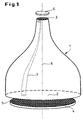
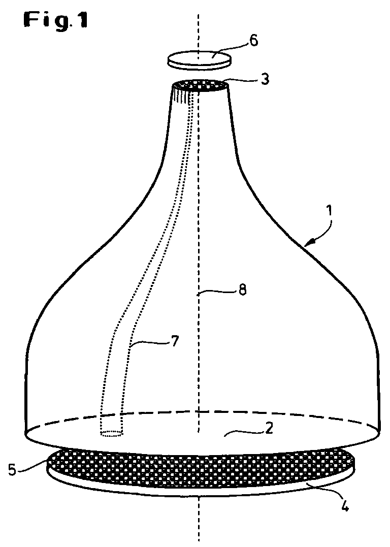
- the basic structure of the optical measuring system can be seen in FIG. 1.
- the most important component is the glass fiber taper element 1 with a large area End face 2 and a small-area end face 3.
- the large end face 2 stands a planar carrier 4 with the test objects 5 arranged thereon and the small one Face 3 an image sensor 6 for detecting and processing the reduced Image of the carrier surface with the test objects 5 opposite.
- the taper element 1 has approximately a bell-shaped contour.
- the individual glass fibers 7 are both on the large end face 2 and on the small end face 3 parallel to the optical axis 8 and thus perpendicular to the respective surfaces 2 and 3 oriented.
- a pivotable luminescence measuring system is shown.
- Carrier 4 a microtiter plate with test holes 9 for those to be examined Objects 5.
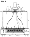
- the measuring system essentially consists of the microtiter plate 4, the Glass fiber taper element 1, an image intensifier 10 and a CCD camera 11. Das whole system is pivotable about a horizontal axis of rotation 12 on a fixed Frame 13 attached.
- the taper element 1 is in a light-tight housing 14 housed.
- 2a corresponds to the basic position, at the microtiter plate 4 as the bottom component and the optical elements 1,10,11 are arranged above it. This position corresponds to the so-called TOP measuring position.
- the whole system is in the position according to FIG.
- FIG. 3 The actual structure of the optical system can be seen in FIG. 3, in which again the TOP position is shown.
- the glass fiber entry window 15 on the image intensifier 10 with the small area Front 3 of the taper element 1 are brought into contact to a efficient transfer of the taper output photons to the photocathode 16 to ensure the image intensifier 10.
- the gap 17 between the taper element 1 and the entrance window 15 can pass through Adjusting screws 18 on the camera support plate 19 in the z direction at zero distance to be brought. This minimizes a spreading that is introduced into the gap 17 Oil drops 20 the reflection losses by adjusting the refractive index at Transition from taper element 1 to detection system 10, 11. The oil has in this Case the same refractive index as the glass of the taper element 1. With the locking screws 21 becomes a rigid connection that is light-tight via a light trap 22 produced between the taper element 1 and the image intensifier 10.
- the microtiter plate 4 (see also FIG. 4) has a multiplicity of cylindrical or rectangular ones Test holes 9 (so-called wells) for receiving the luminescent biological objects 5 on.
- the bottom 23 of the microtiter plate 4 is a special version for the BOTTOM arrangement (according to FIG. 2b) made of an optically transparent material.
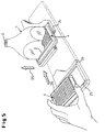
- the microtiter plate 4 is loaded into the measuring apparatus with the help of an extendable drawer 24, which is designed so that it at least for the BOTTOM measuring method in an open frame construction 25 the microtiter plates 4 can accommodate so that the actual measuring area is not covered becomes.
- an extendable drawer 24 which is designed so that it at least for the BOTTOM measuring method in an open frame construction 25 the microtiter plates 4 can accommodate so that the actual measuring area is not covered becomes.
- the drawer 24 is extended, the high voltage is interrupted of the image intensifier 10 coupled to prevent it from being destroyed by too much To protect light.
- retracting the microtiter plate 4 initially remains between its surface 26 and the large-area (lower here) taper surface 2 (see FIG. 3) a gap 27 of a few millimeters in order to hit when entering and thus to avoid possible damage to the taper surface 2.
- the microtiter plate surface 26 and the taper surface 2 in Be brought in contact This is done by means of a resilient height adjustment 29 (only schematically indicated in FIGS. 3 and 5), with which the microtiter plate 4 against the taper element 1 is raised after the microtiter plate 4 is exactly under the large end face 2 of the taper element 1 was positioned, but after exceeding yields to a defined pressure force.
- a resilient height adjustment 29 (only schematically indicated in FIGS. 3 and 5), with which the microtiter plate 4 against the taper element 1 is raised after the microtiter plate 4 is exactly under the large end face 2 of the taper element 1 was positioned, but after exceeding yields to a defined pressure force.
- the bottom of the housing part 30 enclosing the drawer 24 contains an opening closable with a blind plate 31 (see FIG. 3).
- the blind plate is removed and replaced by a window 32.
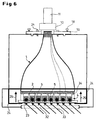
- this window can be in the TOP measuring position at an oblique angle of incidence Fluorescence excitation light 33 is irradiated to examine fluorescent objects to be able to.
- the bottom 23 of the microtiter plate 4 also optically transparent. Between the large end face 2 of the taper element 1 and the microtiter plate 4 is a replaceable, large-area for the fluorescent light selective interference filter 34 arranged to radiate interference from the excitation light 33 suppress.
- the apparatus described can thus quickly and easily from a luminescence measuring system to a fluorescence measuring system with the same high sensitivity.
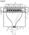
- FIG. 7 Another possibility for expanding the luminescence measuring system is shown in FIG. 7.
- the apparatus pivoted here into the BOTTOM measuring position is additional equipped with a micropipetting system 35, which is above the microtiter plate 4 is arranged.
- the individual pipettes 36 are the individual test holes 9 (wells) assigned to the microtiter plate 4.
- the drawer-like holder 24 for the microtiter plate 4 is like the previously described embodiment with a frame 25 (see Fig. 5) provided so that the top of the microtiter plate 4 for the micropipetting system 35 and the underside accessible for the observation of the luminescence is.
- the bottom 23 of the microtiter plate 4 in turn consists of a optically transparent material to the luminescence radiation of the samples 5 from the Observe the bottom through the bottom 23.
Landscapes
- Health & Medical Sciences (AREA)
- Chemical & Material Sciences (AREA)
- Physics & Mathematics (AREA)
- General Physics & Mathematics (AREA)
- Pathology (AREA)
- Immunology (AREA)
- Life Sciences & Earth Sciences (AREA)
- Analytical Chemistry (AREA)
- Biochemistry (AREA)
- General Health & Medical Sciences (AREA)
- Engineering & Computer Science (AREA)
- Chemical Kinetics & Catalysis (AREA)
- Plasma & Fusion (AREA)
- Nuclear Medicine, Radiotherapy & Molecular Imaging (AREA)
- Investigating, Analyzing Materials By Fluorescence Or Luminescence (AREA)
- Investigating Or Analysing Materials By Optical Means (AREA)
- Photometry And Measurement Of Optical Pulse Characteristics (AREA)
- Optical Fibers, Optical Fiber Cores, And Optical Fiber Bundles (AREA)
- Spectrometry And Color Measurement (AREA)
- Investigating Or Analysing Materials By The Use Of Chemical Reactions (AREA)
Abstract
Bei dem Meßsystem zur Detektion optischer Signale von Mikroassays sind die
signalgebenden Testobjekte 5 auf einer Untersuchungsfläche eines planen Trägers 4
angeordnet. Bei dem planen Träger 4 handelt es sich insbesondere um eine
Mikrotiterplatte für biologische Objekte. Das Meßsystem besteht grundsätzlich aus
einer Abbildungsoptik, die die zu vermessenden Testobjekte 4 derart verkleinert, daß
alle Objekte auf einem zweidimensionalen, lichtempfindlichen Bildsensor 6 vollständig
abgebildet werden. Zur Abbildung wird hier ein hochauflösendes Glasfaser-Taperelement
1 mit einer großflächigen 2 und einer kleinflächigen Stirnseite 3 verwendet,
dessen Stirnseitenflächen 2,3 so gewählt sind, daß die großflächige Stirnfläche
2 mindestens der Untersuchungsfläche des Trägers 4 und die Kleinflächige
Stirnfläche 3 der Größe des Bildsensors 6 entspricht, wobei sich aus dem Verhältnis
der Stirnflächen 2,3 der Verkleinerungsmaßstab der Abbildungsoptik ergibt, um die
Untersuchungsfläche des Trägers 4 vollständig auf den Bildsensor 6 abzubilden.
Description
Die Erfindung geht aus von einem Meßsystem zur Detektion optischer Signale von Mikroassays, bei denen die signalgebenden Testobjekte auf einer Untersuchungsfläche eines planen Träger angeordnet sind, bestehend aus einer Abbildungsoptik, die die zu vermessenden Testobjekte derart verkleinert, daß alle Objekte auf einem zweidimensionalen lichtempfindlichen Bildsensor vollständig abgebildet werden. Die optischen Signale werden durch den Bildsensor in elektronische Bildsignale umgewandelt, die von einem Meßcomputer in bekannter Weise ausgewertet und weiterverarbeitet werden.The invention is based on a measuring system for the detection of optical signals Microassays in which the signaling test objects on a Examination surface of a flat carrier are arranged, consisting of a Imaging optics that reduce the test objects to be measured so that all Objects completely on a two-dimensional light-sensitive image sensor be mapped. The optical signals are in through the image sensor electronic image signals converted by a measuring computer in known Be evaluated and processed further.
Unter 'Testobjekten' werden im Rahmen der Erfindung fluoreszente bzw. lumineszente und/oder fluoreszent- bzw. lumineszent-markierte, auf dem Träger bzw. in Mikrotiterplatten aufgebrachte Proben verstanden, in denen im Falle der Lumineszenz aufgrund molekularer Wechselwirkungen eine chemolumineszente oder biolumineszente Reaktion abläuft, bei der Photonen freigesetzt und nachgewiesen werden können, bzw. im Falle der Fluoreszenz aufgrund der Interaktion eines Fluoreszenzfarbstoffs, mit denen die Objekte markiert sind, bei geeigneter eingestrahlter Anregungsenergie eine Fluoreszenz entsteht, so daß Photonen freigesetzt und nachgewiesen werden können. Die Proben selbst können als gelöste chemische Komponenten vorliegen oder auch als biologische Testsysteme, wie etwa im Fall von enzymatischen Reaktionen, Antigen-Antikörper-Kopplungen, Protein-Bindungsassays, Ligand-Rezeptor-Wechselwirkungen oder Rezeptor-Assays. Dabei kann das biologische Testsystem als zellulärer Assay (adhärente oder Suspensionszellen, vornehmlich Säugerzellen, aber auch Pflanzenzellen, Bakterien, Pilze, Hefen oder Viren) ausgelegt sein oder auch aus subzellulären Bestandteilen, wie z.B. isolierten Zellkernen bzw. Cytoplasma Agglomeraten, oder auch aus kunstlichen Trägern, wie z.B. Kunststoff-beads oder Glas-microspheres, auf denen biologisch aktives Material i.a. zelluläre oder subzelluläre Bestandteile, aufgebracht worden ist, bestehen, wobei durch die Interaktion verschiedener Komponenten ein optisches Signal in Form von Photonen freigesetzt wird.In the context of the invention, “test objects” are understood to mean fluorescent or luminescent and / or fluorescent or luminescent-labeled samples applied to the support or in microtiter plates, in which, in the case of luminescence, a chemiluminescent or bioluminescent reaction takes place due to molecular interactions , in which photons can be released and detected, or in the case of fluorescence due to the interaction of a fluorescent dye with which the objects are marked, fluorescence arises with suitable irradiated excitation energy, so that photons can be released and detected. The samples themselves can be present as dissolved chemical components or as biological test systems, such as in the case of enzymatic reactions, antigen-antibody couplings, protein binding assays, ligand-receptor interactions or receptor assays. The biological test system can be designed as a cellular assay (adherent or suspension cells, primarily mammalian cells, but also plant cells, bacteria, fungi, yeasts or viruses) or from subcellular components , such as isolated cell nuclei or cytoplasmic agglomerates, or also from artificial carriers , such as plastic beads or glass microspheres, on which biologically active material ia cellular or subcellular components have been applied, with the interaction of various components releasing an optical signal in the form of photons.
Ein Problem bei der Lumineszenz- bzw. Fluoreszenz-Messung in biologisch medizinischen Assays besteht häufig darin, daß die mit der biologischen Interaktion korrelierten optischen Signale im allgemeinen derart klein sind, daß biolumineszente bzw. biofluoreszente Ereignisse gewöhnlich nur mit Photomultipliern (Lichtverstärker) detektiert werden können. Im Grenzbereich der Nachweisbarkeit muß von Lumineszenzmeßsystemen (photon counting systems) Gebrauch gemacht werden.A problem with the luminescence or fluorescence measurement in biological medical Assays often consist of those involving biological interaction correlated optical signals are generally so small that bioluminescent or biofluorescent events usually only with photomultipliers (light amplifiers) can be detected. In the limit range of the verifiability of Luminescence measuring systems (photon counting systems) can be used.
Sollen z.B. Mikrotiter-Platten (MTP) mit den Abmessungen von ca. 130 mm x 86 mm, Tiefe ca. 10 - 14 mm, die 96, 384 oder 1536 Testlöcher enthalten, mit bildgebenden Verfahren gleichzeitig optisch vermessen werden, so sind hierfür zweidimensionale Lumineszenzmeßsysteme notwendig. Stand der Technik ist hierbei, die MTP über eine Linsenoptik auf die Photokathode eines Bildverstärkers (Eintrittsfenster) abzubilden und die auftreffenden Photonen nach einer lichtelektrischen Wandlung als Photoelektronen in einer Mehrkanalplatte (MCP=multi channel plate) zu verstärken. Die vervielfachten Elektronen treffen am Austrittsfenster des MCP's auf einen Leuchtphosphor und rufen dort ortsaufgelöst ein gegenüber dem Eingang um bis 1.000.000-fach verstärktes Lichtsignal hervor, das mit einer CCD-Sensor ortsaufgelöst detektiert werden kann.Should e.g. Microtiter plates (MTP) with the dimensions of approx. 130 mm x 86 mm, depth approx. 10 - 14 mm, which contain 96, 384 or 1536 test holes, to be measured optically at the same time with imaging processes, are for this two-dimensional luminescence measuring systems necessary. The state of the art is the MTP via lens optics onto the photocathode of an image intensifier (entrance window) map and the incident photons after a photoelectric Conversion as photoelectrons in a multi-channel plate (MCP = multi channel plate) to reinforce. The multiplied electrons hit the exit window of the MCP on a phosphor and call there in a spatially resolved manner opposite the entrance light signal amplified by up to 1,000,000 times using a CCD sensor can be detected in a spatially resolved manner.
Die Auswertung eines derart verstärkten Ausgangsbild kann mit Hilfe von bildverarbeitenden Prozessen (image-processing) erfolgen, wobei die Helligkeit in jedem Loch einer Mikrotiterplatte als Anzahl der registrierten Photonen-Ereignisse errechnet wird. Entsprechende Systeme sind von verschiedenen Firmen als sog. MTP-Reader im Handel. Für den Fall, daß die Intensitäten hinreichend groß sind und die Integrationszeit keine Rolle spielt, kann man anstelle des Bildverstärkers auch auf handelsübliche, gekühlte CCD-Systeme zurückgreifen. The evaluation of such an amplified output image can be done with the help of image processing Processes (image processing) take place, with the brightness in each Hole in a microtiter plate as the number of registered photon events is calculated. Corresponding systems are known by various companies as so-called MTP readers in stores. In the event that the intensities are sufficiently large and the integration time does not matter, you can also use the instead of the image intensifier use commercially available, cooled CCD systems.
Durch den Vergleich unterschiedlicher Lumineszenzmeßsysteme von verschiedenen Herstellern konnte nachgewiesen werden, daß Photonen, die auf der Photokathode ein Elektron erzeugen, mit den bekannten ein- bzw. zweistufig verstärkten Lumineszenzmeßsystemen detektiert werden können. Eine höhere Verstärkung nach der lichtelektrischen Wandlung, also hinter der Photokathode, führt zu keiner Steigerung der System-Empfindlichkeit.By comparing different luminescence measuring systems from different ones Manufacturers have been able to demonstrate that photons on the photocathode generate an electron with the known one or two-stage amplified Luminescence measuring systems can be detected. A higher gain after the photoelectric conversion, i.e. behind the photocathode, does not lead to any Increased system sensitivity.
Eine Empfindlichkeitssteigerung aufgrund einer höheren Quantenausbeute der Photokathode eines Bildverstärkers ist theoretisch möglich. Physikalische Grenzen und das Ferien entsprechender Detektoren auf dem Markt bieten jedoch derzeit keinen technisch realisierbaren Ausweg.An increase in sensitivity due to a higher quantum yield of the photocathode an image intensifier is theoretically possible. Physical limits and that Holidays of such detectors on the market currently do not offer technically feasible way out.
Um die Abbildung eines Gegenstands, in dem hier beschriebenen Fall die Mikrotiterplatte, auf die Photokathode eines Bildverstärkers zu erzeugen, wird bei allen Herstellern eine lichtstarkes Objektiv benutzt. Einige Hersteller verwenden Standard-Photoobjektive, andere speziell korrigierte Objektive mit großer f-Zahl. Die besten bisher eingesetzten Hochleistungsobjektive haben mit einem Öffnungsverhältnis von ca. 1:1.0 und 50 mm Brennweite bereits eine sehr hohe Lichtstärke. Eine wesentlich lichtstärkere Optik ist aus physikalischen Gründen nicht konstruierbar.To image an object, in the case described here, the microtiter plate, All manufacturers produce on the photocathode of an image intensifier uses a fast lens. Some manufacturers use standard photo lenses, other specially corrected lenses with a large f-number. The best High-performance lenses used up to now have an aperture ratio of approx. 1: 1.0 and 50 mm focal length already a very high light intensity. An essential one optics with higher light intensity cannot be constructed for physical reasons.
Wegen der Dreidimensionalität der Mikrotiterplatte mit ihren ca. 10 -14 mm tiefen Löchern muß bei der konventionellen optischen Abbildung wegen auftretender geometrischer Vignettierung an den Randlöchern eine Gegenstandsweite von ca. 70 cm (Abstand: MTP zum Bildsensor) eingehalten werden. Dementsprechend hoch muß ein Gehäuse sein, in dem die Mikrotiterplatte und das Detektions-System vollständig lichtdicht für das Lumineszenzmeßsystems integriert sind. Dieser geometrische Abstand r zwischen Lichtentstehung und Detektor wirkt sich besonders nachteilig im Hinblick auf die Systemempfindlichkeit aus, da die Intensität mit 1/r2 abnimmt. Das statistisch in einem Loch der Mikrotiterplatte entstehende Lichtquant verläßt das Loch diffus, so daß sich rein geometrisch nur ein Bruchteil (Oberfläche der Halbkugel mit Radius 70 cm im Verhältnis zur Öffnung des Objektives mit einem Durchmesser von 5 cm) von einigen Promille erfassen läßt. Mit konventionellen Abbildungsoptiken wie Linsen- oder auch Spiegelsystemen kann keine grundsätzliche Verbesserung in der System-Empfindlichkeit erreicht werden.Due to the three-dimensionality of the microtiter plate with its approx. 10 -14 mm deep holes, an object width of approx. 70 cm (distance: MTP to the image sensor) must be maintained in conventional optical imaging due to the geometric vignetting at the peripheral holes. Accordingly, a housing must be high in which the microtiter plate and the detection system are integrated in a completely light-tight manner for the luminescence measuring system. This geometric distance r between light generation and detector has a particularly disadvantageous effect on the system sensitivity, since the intensity decreases with 1 / r 2 . The light quantum that statistically arises in a hole in the microtiter plate leaves the hole diffusely, so that, purely geometrically, only a fraction (surface of the hemisphere with a radius of 70 cm in relation to the opening of the objective with a diameter of 5 cm) can be detected by a few parts per thousand. With conventional imaging optics such as lens or mirror systems, no fundamental improvement in system sensitivity can be achieved.
Um beim Screening von biologischen Testsystemen mit optischer Signalverarbeitung beim Test von einigen 100 000 Substanzen einen hohen Probendurchsatz in annehmbarer Zeit zu gewährleisten, muß auf bildgebende Verfahren wegen des Vorteils der Parallelverarbeitung, z.B. in Mikrotiterplatten, zurückgegriffen werden. Wegen der geringen Leuchtstärke der biolumineszenten bzw. biofluoreszenten Reaktionen sind für ein statistisch gesichertes Signal/Rausch-Verhältnis im Photonenzähl-Betrieb häufig Integrationszeiten von einigen Minuten notwendig.To screen biological test systems with optical signal processing when testing some 100,000 substances a high sample throughput in acceptable To ensure time must go to imaging because of the benefit of Parallel processing, e.g. in microtiter plates. Because of the low luminosity of the bioluminescent or biofluorescent reactions for a statistically guaranteed signal / noise ratio in photon counting mode integration times of a few minutes are often necessary.
Um z.B. die Kapazität einer Robotor-Anlage zur Untersuchung von Lumineszenz- oder Fluoreszenzsignalen in Mikrotiterplatten durch Herabsetzung der Integrationszeit für die Vermessung von Mikrotiterplatten zu erhöhen und/oder z.B. die Anzahl von Zellen pro Testloch herabzusetzen und/oder teure Substratmengen für eine Enzymreaktion zu verkleinern, bestand die Aufgabe darin, die Empfindlichkeit der bekannten Lumineszenz- bzw. Fluoreszenzmeßsysteme zu erhöhen.To e.g. the capacity of a robot system for the investigation of luminescence or Fluorescence signals in microtiter plates by reducing the integration time for the measurement of microtiter plates and / or e.g. the number of cells per test hole and / or expensive amounts of substrate for one To reduce the enzyme reaction, the task was to reduce the sensitivity of the known luminescence or fluorescence measuring systems to increase.
Diese Aufgabe wird bei einem optischen Meßsystem mit einer Abbildungsoptik für die zu vermessenden, auf der Untersuchungsfläche des Trägers befindlichen Testobjekte und einem zweidimensionalen lichtempfindlichen Bildsensor, auf den alle Objekte vollständig abgebildet werden, erfindungsgemäß dadurch gelöst, daß die Abbildungsoptik aus einem hochauflösenden Glasfaser-Taperelement mit einer großflächigen und einer kleinflächigen Stirnseite besteht und die Stirnseitenflächen so gewählt sind, daß die großflächige Stirnfläche mindestens der Untersuchungsfläche des Trägers und die kleinflächige Stirnfläche der Größe des Bildsensors entspricht, wobei sich aus dem Verhältnis der Stirnflächen der Verkleinerungsmaßstab der Abbildungsoptik ergibt, um die Untersuchungsfläche des Trägers vollständig auf den Bildsensor abzubilden. Unter 'hochauflösend' ist dabei zu verstehen, daß der Faserdurchmesser der dicht gepackten, nebeneinander liegenden Glasfasern an der großen Stirnfläche des Glasfaser-Taperelements ≤12 µm beträgt.This task is carried out in an optical measuring system with imaging optics for the test objects to be measured, located on the examination surface of the carrier and a two-dimensional, light-sensitive image sensor that everyone can Objects are completely imaged, according to the invention solved in that the imaging optics made of a high-resolution glass fiber taper element with a large area and there is a small-area end face and the end face faces are selected in this way are that the large end face at least the examination surface of the Carrier and the small-area end face corresponds to the size of the image sensor, wherein the reduction scale of the imaging optics from the ratio of the end faces results in the examination surface of the wearer completely on the image sensor map. 'High-resolution' means that the fiber diameter the densely packed, side-by-side glass fibers on the large end face of the glass fiber taper element is ≤12 µm.
Vorzugsweise wird die Erfindung mit Hilfe einer Anordnung realisiert, bei der der planare Träger aus einer Mikrotiterplatte mit einer Vielzahl von Löchern zur Aufnahme der signalgebenden Testobjekte besteht, der Bildsensor einen Bildverstärker und eine Videokamera zur Umwandlung der verstärkten Bildsignale in elektronische Signale umfaßt und das Glasfaser-Taperelement so ausgelegt ist, daß ein das Eintrittsfenster des Bildverstärkers voll ausfüllendes verkleinertes Bild der Mikrotiterplatte erzeugt wird.The invention is preferably implemented with the aid of an arrangement in which the planar carrier made of a microtiter plate with a large number of holes for receiving of the signaling test objects, the image sensor is an image intensifier and a video camera for converting the amplified image signals into electronic ones Includes signals and the glass fiber taper element is designed so that the entry window of the image intensifier, fully filling, reduced image of the microtiter plate is produced.
Um zu vermeiden, daß bei der Verwendung weißer Kunststoffträger eine lichtinduzierte Langzeitphosphoreszenz zu Falschlichtsignalen führt, wird vorteilhaft ein Bildverstärker verwendet, der eine Bialkaliphotokathode aufweist, dessen spektrale Empfindlichkeit bei Wellenlängen > 700 nm < 1 % seiner maximalen Empfindlichkeit ist. Entsprechend einer bevorzugten Ausführung ist für die Mikrotiterplatte eine horizontal verfahrbare und vertikal verstellbare, schubladenartig ausgebildete Halterung vorgesehen, die nach dem horizontalen Einfahren so weit angehoben wird, daß das Glasfaser-Taperelement mit seiner großflächigen Stirnseite in direktem Kontakt mit der Mikrotiterplatte steht.To avoid using a light-induced white plastic carrier Long-term phosphorescence leading to false light signals is advantageous Image intensifier used, which has a bialkal photocathode, the spectral Sensitivity at wavelengths> 700 nm <1% of its maximum sensitivity is. According to a preferred embodiment, there is one for the microtiter plate horizontally movable and vertically adjustable, drawer-like holder provided that is raised so far after the horizontal retraction that the glass fiber taper element with its large face in direct contact with the microtiter plate.
Vorteilhaft steht die kleinflächige Stirnseite des Glasfaser-Taperelements in direktem optischen Kontakt mit dem Eintrittsfenster des Bildverstärkers.The small-area end face of the glass fiber taper element is advantageously in a direct manner optical contact with the entrance window of the image intensifier.
Das Eintrittsfenster des Bildverstärkers mit der nach innen liegenden Photokathode wird vorteilhaft als Glasfaserplatte mit einer numerischen Apertur NA=1.0 ausgerüstet, um eine effiziente optische und geometrisch hochaufgelöste Übertragung des Bildes von der Oberfläche des Glasfaser-Taperelements auf die Photokathode des Bildverstärkers zu gewährleisten. The entrance window of the image intensifier with the photocathode inside is advantageously equipped as a glass fiber plate with a numerical aperture NA = 1.0, for an efficient optical and geometrically high resolution transmission of the Image from the surface of the glass fiber taper on the photocathode of the To ensure image intensifier.
Zur Minimierung von Reflexionsvelusten ist ferner vorgesehen, daß ein zwischen dem Glasfaser-Taperelement und dem Eintrittsfenster des Bildverstärkers verbleibender Luftspalt mit einem Ölfilm ausgefüllt ist, dessen Brechungsindex mit dem Brechungsindex der Taperelements übereinstimmt.To minimize reflection velocities, it is also provided that an between the glass fiber taper element and the entrance window of the image intensifier remaining Air gap is filled with an oil film, the refractive index of which with Refractive index of the taper elements matches.
Zur Untersuchung von biofluoreszenten Objekten in einer Mikrotiterplatte wird die erfindungsgemäße Apparatur in der Weise abgewandelt, daß die Mikrotiterplane einen optisch transparenten Boden aufweist, daß die schubladenartige Halterung als Rahmenkonstruktion ausgebildet ist und daß unterhalb der Mikrotiterplatte eine Lichtquelle zur Fluoreszenzanregung angeordnet ist, die ein zur optischen Achse schräg einfallendes Lichtbündel erzeugt.To examine biofluorescent objects in a microtiter plate, the The apparatus according to the invention modified in such a way that the microtiter tarpaulin has an optically transparent bottom that the drawer-like holder as Frame construction is formed and that below the microtiter plate Light source for fluorescence excitation is arranged, one to the optical axis obliquely incident light beam generated.
Eine Weiterentwicklung der Erfindung ist dadurch gekennzeichnet, daß die gesamte
Apparatur um eine horizontale Achse um 180° schwenkbar ist und folgende weitere
Merkmale aufweist:
Eine derartige Anordnung erlaubt die in situ-Beobachtung der Lumineszenz von biologischen Objekten unter dem Einfluß eines hinzugefügten Reagens. Hierdurch sind kinetische Biolumineszenzuntersuchungen möglich, die das dynamische Wirkprofil von pharmakologisch aktiven Substanzen wiedergeben.Such an arrangement allows the luminescence of biological objects under the influence of an added reagent. Hereby kinetic bioluminescence studies are possible that show the dynamic effect profile of pharmacologically active substances.
Mit der Erfindung werden folgende Vorteile erzielt:
- Im Vergleich zu herkömmlichen Mikrotiterplatten-Lumineszenzmeßsystemen
ist das neue System um den
Faktor 10 lichtempfindlicher. Auf diese Weise sind sehr lichtschwache biolumineszente Reaktionen überhaupt erst nachweisbar. - Bei gleichem Signal/Rausch-Verhältnis läßt sich die Integrationszeit um den
Faktor 10 erniedrigen. Alternativ kann bei gleichem Signal/Rausch-Verhältnis die Menge der biologischen Objekte (z.B. die Zellzahl/Mikrotiterplatten) um denFaktor 10 vermindert werden oder umgekehrt bei gleicher Substratmenge der Probendurchsatz um denFaktor 10 vergrößert werden. - Bei gleichem Signal/Rausch-Verhältnis kann die Substratmenge, die in einer
bio-chemischen Reaktion die zu detektierenden Photonen freisetzt, um den
Faktor 10 erniedrigt werden. - Bei gleichem Signal/Rausch-Verhältnis kann wegen der hohen Empfindlichkeit
die Fluoreszenzfarbstoffkonzentration um den
Faktor 10 gesenkt (Verringerung der Nebenwirkung auf das biologische System) bzw. die Meßzeiten um denFaktor 10 gekürzt (Reduzierung der Ausbleicheffekte) werden. - Aufgrund der senkrechten Lichterfassung der Taperoptik an der Mikrotiterplatte treten keine Vignettierungseffekte auf.
- Aufgrund des kleinen Aufbaus des Systems infolge der geringen Bauhöhe der Taperoptik von ca. 16 cm im Vergleich zum Abstand bei der Linsenabbildung von ca. 70 cm läßt sich ein Wechsel von einem Aufsicht- zu einem Durchsicht-Meßverfahren ohne Umbauarbeiten durch eine 180°- Drehung des Systems um die Schwerpunktachse realisieren.
- Compared to conventional microtiter plate luminescence measuring systems, the new system is more sensitive to light by a factor of 10. In this way, very faint bioluminescent reactions can be detected in the first place.
- With the same signal-to-noise ratio, the integration time can be reduced by a factor of 10. Alternatively, with the same signal / noise ratio, the amount of biological objects (eg the number of cells / microtiter plates) can be reduced by a factor of 10 or, conversely, the sample throughput can be increased by a factor of 10 with the same amount of substrate.
- With the same signal-to-noise ratio, the amount of substrate that releases the photons to be detected in a bio-chemical reaction can be reduced by a factor of 10.
- With the same signal-to-noise ratio, the high sensitivity can reduce the fluorescent dye concentration by a factor of 10 (reduction of the side effect on the biological system) or the measurement times can be shortened by a factor of 10 (reduction of the fading effects).
- Due to the vertical light detection of the taper optics on the microtiter plate, there are no vignetting effects.
- Due to the small structure of the system due to the low overall height of the taper optics of approx. 16 cm compared to the distance for the lens image of approx. 70 cm, a change from a top-view to a see-through measurement method can be carried out without conversion work by a 180 ° rotation of the system around the center of gravity.
Im folgenden wird die Erfindung an Hand von Zeichnungen und Ausführungsbeispielen näher erläutert. Es zeigen:
- Fig. 1
- den prinzipiellen Aufbau des optischen Meßsystems
- Fig.2a
- eine schematische Ansicht eines Lumineszenzmeßsystems in der Grundstellung (TOP-Stellung)
- Fig. 2b
- eine schematische Ansicht des Lumineszenzmeßsystems in einer gegenüber
- Fig. 2a
- um 180 ° gedrehten Stellung (BOTTOM-Stellung)
- Fig. 3
- den Aufbau des Meßsystems für lumineszente biologische Objekte
- Fig. 4
- eine Draufsicht einer Mikrotiterplatte
- Fig. 5
- die schubladenartige Halterung für die Mikrotiterplatte
- Fig. 6
- den prinzipiellen Aufbau eines Meßsystems zur Untersuchung fluoreszierender biologischer Objekte mit schräg einfallendem Anregungslicht
- Fig. 7
- den prinzipiellen Aufbau eines Lumineszenzmeßsystems in der BOTTOM-Stellung mit einer Pipettiereinrichtung zur Untersuchung dynamischer Vorgänge bei lumineszenten biologischen Objekten
- Fig. 1
- the basic structure of the optical measuring system
- Fig.2a
- a schematic view of a luminescence measuring system in the basic position (TOP position)
- Fig. 2b
- a schematic view of the luminescence measuring system in one opposite
- Fig. 2a
- position rotated by 180 ° (BOTTOM position)
- Fig. 3
- the construction of the measuring system for luminescent biological objects
- Fig. 4
- a top view of a microtiter plate
- Fig. 5
- the drawer-like holder for the microtiter plate
- Fig. 6
- the basic structure of a measuring system for examining fluorescent biological objects with obliquely incident excitation light
- Fig. 7
- the basic structure of a luminescence measuring system in the BOTTOM position with a pipetting device for the investigation of dynamic processes in luminescent biological objects
Bei der Erfindung wird die Eigenschaft von Lichtleitern (Glas- oder Polymerfasern)
genutzt, Lichtsignale, insbesondere auch einzelne Photonen, in einem weiten
Spektralbereich zu übertragen. Durch eine geordnete Anordung vieler Fasern in einer
xy-Fläche ist es möglich, ein Helligkeitsbild als Intensitäts-Rastergrafik an einem
anderen Ort darzustellen (Bildleiter). Hierzu muß jeder Punkt xgi, ygi in der Gegenstandsebene
g einem Punkt xbi, ybi in der Bildebene b entsprechen. Wird jede Faser
des Bildleiters auf ihrem Weg von der Gegenstandsebene zur Bildebene geometrisch
verjüngt, indem ihr Durchmesser verkleinert wird, so wird das Gegenstandsbild um
den
Die Eingangsfenster der Bildverstärker-Photokathoden von kommerziellen Photon-Counting-Systemen haben einen Durchmesser von 12 mm, 18 mm, 25 mm oder 40 mm. Mit größer werdenden Fläche nimmt der Preis der Bildverstärker überproportional zu. Andererseits ist ein möglichst geringer Verkleinerungsfaktor fv für das Taperelement anzustreben, weil dessen Apertur und damit seine Leistung in der Übertragung optischer Signale mit 1/fv abnimmt. Als vertretbarer Kompromiß zwischen Kosten und Nutzen wurde bei der vorliegenden Erfindung ein Bildverstärker mit 25 mm Durchmesser gewählt. In diesem Fall ergibt sich eine rechnerische numerische Appertur von 0.167 entsprechend einem Öffnungswinkel von ca. 20 Grad im Vergleich zu dem viel kleineren Öffnungswinkel eines f 1:1,0-Objektives in einer Entfernung von 70 cm von 0.1 Grad. The entrance windows of the image intensifier photocathodes of commercial photon counting systems have a diameter of 12 mm, 18 mm, or 25 mm 40 mm. As the area increases, the price of the image intensifier increases disproportionately to. On the other hand, the smallest possible reduction factor fv is for the To aim for taper element because of its aperture and thus its performance in the Transmission of optical signals decreases with 1 / fv. As an acceptable compromise In the present invention, an image intensifier was used between cost and benefit with a diameter of 25 mm. In this case there is a mathematical calculation numerical aperture of 0.167 corresponding to an opening angle of approx. 20 degrees compared to the much smaller aperture angle of an f 1: 1.0 lens at a distance of 70 cm from 0.1 degrees.
Infolge dieses im Vergleich zu Linsen/Spiegel-Abbildungssystemen größeren Öffnungswinkels der Glasfaseroptik wird die Photonen-Sammeleigenschaft mit Hilfe des Taperelements um ein Vielfaches gegenüber der herkömmlichen Optik verbessert. Vergleichende Messungen mit dem besten bekannten Photon-Counting-System, einmal mit Linsenoptik (Leica Noctilux f 1:1.0) und zum anderen mit der Taperoptik ausgerüstet, beweisen eine Empfindlichkeitssteigerung um 1000 %. Die Empfindlichkeit eines Systems für die Übertragung von optischen Signalen konnte mit Hilfe der aus dem Glasfaser-Taperelement bestehenden Abbildungsoptik um den Faktor 10 gesteigert werden.As a result, this is larger compared to lens / mirror imaging systems With the help of the opening angle of the glass fiber optics, the photon collecting property becomes of the taper element has been improved many times over compared to conventional optics. Comparative measurements with the best known Photon counting system, once with lens optics (Leica Noctilux f 1: 1.0) and for others equipped with the taper optics prove an increase in sensitivity around 1000%. The sensitivity of a system for the transmission of optical Signals could be generated using the imaging optics consisting of the glass fiber taper element can be increased by a factor of 10.
Der prinzipielle Aufbau des optischen Meßsystems ist aus Fig. 1 ersichtlich. Die
wichtigste Komponente ist dabei das Glasfaser-Taperelement 1 mit einer großflächigen
Stirnseite 2 und einer kleinflächigen Stirnseite 3. Der großen Stirnfläche 2 steht
ein planarer Träger 4 mit den darauf angeordneten Testobjekten 5 und der kleinen
Stirnfläche 3 ein Bildsensor 6 zur Erfassung und Weiterverarbeitung des verkleinerten
Bildes der Trägeroberfläche mit den Testobjekten 5 gegenüber. Das Taperelement
1 hat annähernd eine glockenförmige Kontur. Die einzelnen Glasfasern 7
sind sowohl an der großen Stirnfläche 2, als auch an der kleinen Stirnfläche 3
parallel zur optischen Achse 8 und damit senkrecht zu den jeweiligen Flächen 2 und
3 orientiert.The basic structure of the optical measuring system can be seen in FIG. 1. The
The most important component is the glass
Gemäß Fig. 2a und 2b ist ein schwenkbares Lumineszenzmeßsystem dargestellt. Der
Träger 4 ist hier eine Mikrotiterplatte mit Testlöchern 9 für die zu untersuchenden
Objekte 5. Das Meßsystem besteht im Wesentlichen aus der Mikrotiterplatte 4, dem
Glasfaser-Taperelement 1, einem Bildverstärker 10 und einer CCD-Kamera 11. Das
ganze System ist um eine horizontale Drehachse 12 schwenkbar an einem feststehenden
Gestell 13 angebracht. Das Taperelement 1 ist in einem lichtdichten Gehäuse
14 untergebracht. Die Position gemäß Fig. 2a entspricht der Grundstellung, bei
der die Mikrotiterplatte 4 als unterstes Bauelement und die optischen Elemente
1,10,11 oberhalb davon angeordnet sind. Diese Position entspricht der sog. TOP-Meßposition.
Im Gegensatz dazu ist in der Position gemäß Fig. 2b das ganze System
um 180° um die Drehachse 12 geschwenkt. In diesem Fall befindet sich die
Mikrotiterplatte 4 ganz oben und ist somit auch von oben her zugänglich, während
die optischen Komponenten 1,10,11 unterhalb der Mikrotiterplatte 4 liegen. Diese
Position entspricht der sog. BOTTOM-Meßposition. Bei der Schwenkung um
180 Grad wird also das lichtdichte Gehäuse 14 mit dem Taperelement 1 als Verkleinerungsoptik
und dem angeflanschten Photodetektionssystem 10,11 als starre
Einheit gedreht. Die großflächige Stirnseite des Taperelements 1 ist der Mikrotiterplatte
4 und seine kleinflächige Stirnseite dem Bildverstärker 10 zugewandt. Der
Verkleinerungsfaktor des Taperelements 1 ist so gewählt, daß das verkleinerte Bild
der Mikrotiterplatte 4 das Eintrittsfenster des Bildverstärkers 10 voll ausfüllt. Bei
Meßsystemen dieser Art ist ein Verkleinerungsfaktor im Bereich von 1:2 bis 1:6 als
optimal anzusehen.2a and 2b, a pivotable luminescence measuring system is shown. Of the
Der eigentliche Aufbau des optischen Systems ist aus Fig. 3 ersichtlich, in der
wiederum die TOP-Position dargestellt ist. Bei der Einrichtung und Justierung des
Systems muß das Glasfaser-Eintrittsfenster 15 am Bildverstärker 10 mit der Kleinflächigen
Stirnseite 3 des Taperelements 1 in Kontakt gebracht werden, um eine
effiziente Übertragung der Taper-ausgangsseitigen Photonen auf die Photokathode
16 des Bildverstärkers 10 sicherzustellen.The actual structure of the optical system can be seen in FIG. 3, in which
again the TOP position is shown. When setting up and adjusting the
Systems must the glass fiber entry window 15 on the
Bei der Verwendung von weißen Kunststoff-Trägern, z.B. von weißen Mikrotiterplanen wird zweckmäßigerweise auf einen Bildverstärker mit einer Bialkali-Photokathode zurückgegriffen, weil auf Grund der speziellen spektralen Empfindlichkeit einer solchen Photokathode verhindert wird, daß die allen weißen Mikrotiterplatten anhaftende negative Eigenschaft einer lichtinduzierten Langzeitphosphoreszenz, die schwerpunktmäßig bei ca 800 nm auftritt, ein nicht erkennbares Falschlichtsignal und damit eine Empfindlichkeitsbegrenzung hervorruft. Da die Spektralempfindlichkeit der Bialkali-Photokathode oberhalb 700 nm praktisch Null ist wird das von der Langzeitphosphoreszenz stammende Falschlicht unterdrückt. When using white plastic supports, e.g. of white microtiter tarps is expediently on an image intensifier with a bialkali photocathode resorted to because of the special spectral sensitivity Such a photocathode prevents all white microtiter plates adherent negative property of a light-induced long-term phosphorescence, the mainly occurs at approx. 800 nm, an undetectable false light signal and thus causes a sensitivity limitation. Because the spectral sensitivity the bialkali photocathode is practically zero above 700 nm Long-term phosphorescence false light suppressed.
Der Spalt 17 zwischen Taperelement 1 und dem Eingangsfenster 15 kann durch
Justierschrauben 18 an der Kamera-Trägerplatte 19 in z-Richtung auf Null-Abstand
gebracht werden. Dabei minimiert ein in den Spalt 17 eingebrachter, sich ausbreitender
Öltropfen 20 die Reflexionsverluste durch Anpassung des Brechungsindex beim
Übergang vom Taperelement 1 zum Detektionssystem 10,11. Das Öl hat in diesem
Fall denselben Brechungsindex wie das Glas des Taperelements 1. Mit den Arretierschrauben
21 wird eine starre, über eine Lichtfalle 22 lichtdichte Verbindung
zwischen dem Taperelement 1 und dem Bildverstärker 10 hergestellt.The
Die Mikrotiterplatte 4 (s. auch Fig. 4) weist eine Vielzahl zylindrischer oder rechteckiger
Testlöcher 9 (sog. wells) zur Aufnahme der lumineszenten biologischen Objekte
5 auf. Der Boden 23 der Mikrotiterplatte 4 besteht als Spezialausführung für die
BOTTOM-Anordnung (gem. Fig. 2b) aus einem optisch transparenten Material.The microtiter plate 4 (see also FIG. 4) has a multiplicity of cylindrical or rectangular ones
Test holes 9 (so-called wells) for receiving the luminescent
Anhand von Fig. 5 wird die schubladenförmige Halterung für die Mikrotiterplatte 4
näher erläutert. Die Beschickung der Meßapparatur mit der Mikrotiterplatte 4 erfolgt
mit Hilfe einer ausfahrbaren Schublade 24, die so ausgebildet ist, daß sie zumindest
für das BOTTOM-Meßverfahren in einer offenen Rahmenkonstruktion 25 die Mikrotiterplatten
4 aufnehmen kann, so daß die eigentliche Meßfläche nicht abgedeckt
wird. Mit dem Ausfahren der Schublade 24 ist eine Unterbrechung der Hochspannung
des Bildverstärkers 10 gekoppelt, um diesen vor Zerstörung durch zuviel
Licht zu schützen. Bei dem Einfahren der Mikrotiterplatte 4 bleibt zunächst zwischen
ihrer Oberfläche 26 und der großflächigen (hier unteren) Taperoberfläche 2 (s. Fig. 3)
ein Spalt 27 von einigen Millimetern, um ein Anstoßen beim Einfahren und damit
eine mögliche Beschädigung der Taperoberfläche 2 zu vermeiden. Um die Bedingungen
für eine optimale Signaleinkopplung bei optimaler Ortsauflösung zu erfüllen,
müssen die Mikrotiterplattenoberfläche 26 und die Taperoberfläche 2 in
Kontakt gebracht werden. Dies geschieht mittels einer federnden Höhenverstellung
29 (in Fig. 3 und 5 nur schematisch angedeutet), mit der die Mikrotiterplatte 4 gegen
das Taperelement 1 angehoben wird, nachdem die Mikrotiterplatte 4 genau unter der
großen Stirnfläche 2 des Taperelements 1 positioniert wurde, die aber nach Über-schreiten
einer definierten Andruckkraft nachgibt. Hierdurch lassen sich Mikrotiterplatten
4 mit unterschiedlichen Höhenmaßen spielfrei an die Taperoberfläche 2 anpassen.
Der Boden des die Schublade 24 umschließenden Gehäuseteils 30 enthält
einen mit einer Blindplatte 31 verschließbaren Durchbruch (s. Fig. 3).5, the drawer-shaped holder for the
Gemäß Fig. 6 ist die Blindplatte entfernt und durch ein Fenster 32 ersetzt. Durch
dieses Fenster kann in der TOP-Meßposition unter einem schrägen Einfallswinkel
Fluoreszenzanregungslicht 33 eingestrahlt werden, um fluoreszierende Objekte untersuchen
zu können. Bei dieser Anordnung ist der Boden 23 der Mikrotiterplatte 4
ebenfalls optisch transparent. Zwischen der großen Stirnfläche 2 des Taperelements 1
und der Mikrotiterplatte 4 ist ein auswechselbares, großflächiges, für das Fluoreszenzlicht
selektives Interferenzfilter 34 angeordnet, um Störstrählung vom Anregungslicht
33 zu unterdrücken. Die beschriebene Apparatur kann somit schnell und
problemlos von einem Lumineszenzmeßsystem auf ein Fluoreszenzmeßsystem mit
der gleichen hohen Empfindlichkeit umgerüstet werden.6, the blind plate is removed and replaced by a
Eine weitere Ausbaumöglichkeit des Lumineszenzmeßsystems ist in Fig. 7 dargestellt.
Die hier in die BOTTOM-Meßposition geschwenkte Apparatur ist zusätzlich
mit einem Mikropipettiersystem 35 ausgestattet, das oberhalb der Mikrotiterplatte 4
angeordnet ist. Dabei sind die Einzelpipetten 36 den einzelnen Testlöchern 9 (Wells)
der Mikrotiterplatte 4 zugeordnet. Die schubladenartige Halterung 24 für die Mikrotiterplatte
4 ist wie bei der zuvor beschriebenen Ausführung mit einem Rahmen 25
(s. Fig. 5) versehen, damit die Oberseite der Mikrotiterplatte 4 für das Mikropipettiersystem
35 und die Unterseite für die Beobachtung der Lumineszenz zuganglich
ist. Der Boden 23 der Mikrotiterplatte 4 besteht wiederum aus einem
optisch transparenten Material, um die Lumineszenzstrahlung der Proben 5 von der
Unterseite her durch den Boden 23 zu beobachten. Diese Erweiterung erlaubt eine
dynamische Untersuchung von lumineszenten biologischen Objekten z.B. unter dem
Einfluß von Reaktionsflüssigkeiten, die über die Pipetten 36 zugeführt werden
können. Auf diese Weise sind kinetische Biolumineszenz-Untersuchungen mit einer
Zeitauflösung von 40 ms (Video-Norm) möglich, die das dynamische Wirkungsprofil
von pharmakologisch aktiven Substanzen an den biologischen Objekten widerspiegeln.
Bei schnell abklingenden Lumineszenzreaktionen des biologischen Systems
in der Größenordnung einiger 100 ms bis 2 s lassen sich nur auf diese Weise
Substanzeffekte untersuchen.Another possibility for expanding the luminescence measuring system is shown in FIG. 7.
The apparatus pivoted here into the BOTTOM measuring position is additional
equipped with a
Claims (9)
Applications Claiming Priority (2)
| Application Number | Priority Date | Filing Date | Title |
|---|---|---|---|
| DE19745373A DE19745373A1 (en) | 1997-10-14 | 1997-10-14 | Optical measuring system for the detection of luminescence or fluorescence signals |
| DE19745373 | 1997-10-14 |
Publications (3)
| Publication Number | Publication Date |
|---|---|
| EP0909947A2 true EP0909947A2 (en) | 1999-04-21 |
| EP0909947A3 EP0909947A3 (en) | 1999-06-09 |
| EP0909947B1 EP0909947B1 (en) | 2003-07-09 |
Family
ID=7845519
Family Applications (1)
| Application Number | Title | Priority Date | Filing Date |
|---|---|---|---|
| EP98118580A Expired - Lifetime EP0909947B1 (en) | 1997-10-14 | 1998-10-01 | Optical measurement system for detecting luminescence or fluorescence emissions |
Country Status (10)
| Country | Link |
|---|---|
| US (1) | US6191852B1 (en) |
| EP (1) | EP0909947B1 (en) |
| JP (1) | JP4445596B2 (en) |
| AT (1) | ATE244882T1 (en) |
| CA (1) | CA2249908C (en) |
| DE (2) | DE19745373A1 (en) |
| DK (1) | DK0909947T3 (en) |
| ES (1) | ES2202710T3 (en) |
| IL (1) | IL126506A (en) |
| PT (1) | PT909947E (en) |
Cited By (6)
| Publication number | Priority date | Publication date | Assignee | Title |
|---|---|---|---|---|
| GB2390155A (en) * | 2001-01-03 | 2003-12-31 | Packard Instrument Co Inc | System for measuring fluorescence and luminescence |
| EP1305569A4 (en) * | 2000-05-22 | 2005-08-03 | Lockheed Corp | Fiber optic taper coupled position sensing module |
| EP2843392A3 (en) * | 2013-09-02 | 2015-03-11 | Roche Diagnostics GmbH | Apparatus for photometric measurement of biological liquids |
| JP2016515207A (en) * | 2013-03-14 | 2016-05-26 | ジェン−プローブ・インコーポレーテッド | Apparatus for detecting signal emission from multiple fluorescent sources |
| DE102016201440A1 (en) | 2016-02-01 | 2017-08-03 | Carl Zeiss Microscopy Gmbh | Image acquisition device of a microscope arrangement, microscope arrangement and microscopy method |
| DE102019128546A1 (en) * | 2019-10-22 | 2021-04-22 | Byonoy Gmbh | Transmission device for examining samples in wells of a microtiter plate and method for examining samples in wells of a microtiter plate by means of transmission |
Families Citing this family (131)
| Publication number | Priority date | Publication date | Assignee | Title |
|---|---|---|---|---|
| WO1998001744A1 (en) * | 1996-07-10 | 1998-01-15 | Cambridge Imaging Limited | Improved imaging system for fluorescence assays |
| US6036924A (en) | 1997-12-04 | 2000-03-14 | Hewlett-Packard Company | Cassette of lancet cartridges for sampling blood |
| US6391005B1 (en) | 1998-03-30 | 2002-05-21 | Agilent Technologies, Inc. | Apparatus and method for penetration with shaft having a sensor for sensing penetration depth |
| US6096205A (en) * | 1998-05-13 | 2000-08-01 | The Regents Of The University Of California | Hand portable thin-layer chromatography system |
| US7612020B2 (en) | 1998-12-28 | 2009-11-03 | Illumina, Inc. | Composite arrays utilizing microspheres with a hybridization chamber |
| DE19919092A1 (en) * | 1999-04-27 | 2000-11-02 | Zeiss Carl Jena Gmbh | Arrangement for the optical evaluation of an array of objects |
| DE19919539C5 (en) * | 1999-04-29 | 2004-12-09 | Gerhard Lewandovski | Method for measuring the activity of a biologically active substance in a histological preparation |
| DE19930607C2 (en) * | 1999-07-02 | 2002-08-01 | Max Planck Gesellschaft | Method for obtaining data which provide information about the kinetics of the reactions of reactants in a large number of samples and device for carrying out the method |
| US6527708B1 (en) * | 1999-07-02 | 2003-03-04 | Pentax Corporation | Endoscope system |
| JP5079958B2 (en) * | 1999-07-21 | 2012-11-21 | アプライド バイオシステムズ リミテッド ライアビリティー カンパニー | Luminescence detection workstation |
| DE19935433A1 (en) * | 1999-08-01 | 2001-03-01 | Febit Ferrarius Biotech Gmbh | Microfluidic reaction carrier |
| DE19936999C2 (en) | 1999-08-02 | 2002-03-14 | Jena Optronik Gmbh | Arrangement for detecting the fluorescence radiation from matrix-shaped sample carriers |
| US6770441B2 (en) * | 2000-02-10 | 2004-08-03 | Illumina, Inc. | Array compositions and methods of making same |
| US6627159B1 (en) * | 2000-06-28 | 2003-09-30 | 3M Innovative Properties Company | Centrifugal filling of sample processing devices |
| US8097471B2 (en) * | 2000-11-10 | 2012-01-17 | 3M Innovative Properties Company | Sample processing devices |
| US8641644B2 (en) | 2000-11-21 | 2014-02-04 | Sanofi-Aventis Deutschland Gmbh | Blood testing apparatus having a rotatable cartridge with multiple lancing elements and testing means |
| AU2002320094A1 (en) | 2001-06-12 | 2002-12-23 | Pelikan Technologies, Inc. | Integrated blood sampling analysis system with multi-use sampling module |
| US7025774B2 (en) | 2001-06-12 | 2006-04-11 | Pelikan Technologies, Inc. | Tissue penetration device |
| US8337419B2 (en) | 2002-04-19 | 2012-12-25 | Sanofi-Aventis Deutschland Gmbh | Tissue penetration device |
| DE60234598D1 (en) | 2001-06-12 | 2010-01-14 | Pelikan Technologies Inc | SELF-OPTIMIZING LANZET DEVICE WITH ADAPTANT FOR TEMPORAL FLUCTUATIONS OF SKIN PROPERTIES |
| WO2002100252A2 (en) | 2001-06-12 | 2002-12-19 | Pelikan Technologies, Inc. | Blood sampling apparatus and method |
| DE60239132D1 (en) | 2001-06-12 | 2011-03-24 | Pelikan Technologies Inc | APPARATUS FOR INCREASING THE SUCCESS RATE IN RESPECT OF BLOOD EXPLOITATION OBTAINED BY A FINGERSTICK |
| US9795747B2 (en) | 2010-06-02 | 2017-10-24 | Sanofi-Aventis Deutschland Gmbh | Methods and apparatus for lancet actuation |
| EP1404235A4 (en) | 2001-06-12 | 2008-08-20 | Pelikan Technologies Inc | METHOD AND APPARATUS FOR INTEGRATED LANCET LAUNCH DEVICE ON BLOOD SAMPLING CARTRIDGE |
| US9427532B2 (en) | 2001-06-12 | 2016-08-30 | Sanofi-Aventis Deutschland Gmbh | Tissue penetration device |
| AU2002315180A1 (en) | 2001-06-12 | 2002-12-23 | Pelikan Technologies, Inc. | Electric lancet actuator |
| US7981056B2 (en) | 2002-04-19 | 2011-07-19 | Pelikan Technologies, Inc. | Methods and apparatus for lancet actuation |
| US9226699B2 (en) | 2002-04-19 | 2016-01-05 | Sanofi-Aventis Deutschland Gmbh | Body fluid sampling module with a continuous compression tissue interface surface |
| DE10131687A1 (en) * | 2001-06-29 | 2003-01-16 | Eppendorf Ag | Device for carrying out nucleic acid amplification reactions while simultaneously monitoring the formation of amplification products |
| DE10145221A1 (en) * | 2001-09-13 | 2003-04-10 | Lavision Biotec Gmbh | Apparatus for detecting luminescence from micro-arrays, comprises directing white light at the micro-array through an optical system and optically gathering the emitted fluorescence at a detector to be digitized for processing |
| US7344894B2 (en) | 2001-10-16 | 2008-03-18 | Agilent Technologies, Inc. | Thermal regulation of fluidic samples within a diagnostic cartridge |
| US7141058B2 (en) | 2002-04-19 | 2006-11-28 | Pelikan Technologies, Inc. | Method and apparatus for a body fluid sampling device using illumination |
| US7198606B2 (en) | 2002-04-19 | 2007-04-03 | Pelikan Technologies, Inc. | Method and apparatus for a multi-use body fluid sampling device with analyte sensing |
| US7297122B2 (en) | 2002-04-19 | 2007-11-20 | Pelikan Technologies, Inc. | Method and apparatus for penetrating tissue |
| US8702624B2 (en) | 2006-09-29 | 2014-04-22 | Sanofi-Aventis Deutschland Gmbh | Analyte measurement device with a single shot actuator |
| US8579831B2 (en) | 2002-04-19 | 2013-11-12 | Sanofi-Aventis Deutschland Gmbh | Method and apparatus for penetrating tissue |
| US7410468B2 (en) | 2002-04-19 | 2008-08-12 | Pelikan Technologies, Inc. | Method and apparatus for penetrating tissue |
| US7374544B2 (en) | 2002-04-19 | 2008-05-20 | Pelikan Technologies, Inc. | Method and apparatus for penetrating tissue |
| US7371247B2 (en) | 2002-04-19 | 2008-05-13 | Pelikan Technologies, Inc | Method and apparatus for penetrating tissue |
| US7674232B2 (en) | 2002-04-19 | 2010-03-09 | Pelikan Technologies, Inc. | Method and apparatus for penetrating tissue |
| US7491178B2 (en) | 2002-04-19 | 2009-02-17 | Pelikan Technologies, Inc. | Method and apparatus for penetrating tissue |
| US8784335B2 (en) | 2002-04-19 | 2014-07-22 | Sanofi-Aventis Deutschland Gmbh | Body fluid sampling device with a capacitive sensor |
| US7258693B2 (en) | 2002-04-19 | 2007-08-21 | Pelikan Technologies, Inc. | Device and method for variable speed lancet |
| US7909778B2 (en) | 2002-04-19 | 2011-03-22 | Pelikan Technologies, Inc. | Method and apparatus for penetrating tissue |
| US7901362B2 (en) | 2002-04-19 | 2011-03-08 | Pelikan Technologies, Inc. | Method and apparatus for penetrating tissue |
| US7524293B2 (en) | 2002-04-19 | 2009-04-28 | Pelikan Technologies, Inc. | Method and apparatus for penetrating tissue |
| US7582099B2 (en) * | 2002-04-19 | 2009-09-01 | Pelikan Technologies, Inc | Method and apparatus for penetrating tissue |
| US8221334B2 (en) | 2002-04-19 | 2012-07-17 | Sanofi-Aventis Deutschland Gmbh | Method and apparatus for penetrating tissue |
| US7485128B2 (en) | 2002-04-19 | 2009-02-03 | Pelikan Technologies, Inc. | Method and apparatus for penetrating tissue |
| US7232451B2 (en) | 2002-04-19 | 2007-06-19 | Pelikan Technologies, Inc. | Method and apparatus for penetrating tissue |
| US7717863B2 (en) | 2002-04-19 | 2010-05-18 | Pelikan Technologies, Inc. | Method and apparatus for penetrating tissue |
| US7892185B2 (en) | 2002-04-19 | 2011-02-22 | Pelikan Technologies, Inc. | Method and apparatus for body fluid sampling and analyte sensing |
| US7547287B2 (en) | 2002-04-19 | 2009-06-16 | Pelikan Technologies, Inc. | Method and apparatus for penetrating tissue |
| US9314194B2 (en) | 2002-04-19 | 2016-04-19 | Sanofi-Aventis Deutschland Gmbh | Tissue penetration device |
| US7244265B2 (en) | 2002-04-19 | 2007-07-17 | Pelikan Technologies, Inc. | Method and apparatus for penetrating tissue |
| US8267870B2 (en) | 2002-04-19 | 2012-09-18 | Sanofi-Aventis Deutschland Gmbh | Method and apparatus for body fluid sampling with hybrid actuation |
| US8360992B2 (en) | 2002-04-19 | 2013-01-29 | Sanofi-Aventis Deutschland Gmbh | Method and apparatus for penetrating tissue |
| US7648468B2 (en) | 2002-04-19 | 2010-01-19 | Pelikon Technologies, Inc. | Method and apparatus for penetrating tissue |
| US9248267B2 (en) | 2002-04-19 | 2016-02-02 | Sanofi-Aventis Deustchland Gmbh | Tissue penetration device |
| US7892183B2 (en) | 2002-04-19 | 2011-02-22 | Pelikan Technologies, Inc. | Method and apparatus for body fluid sampling and analyte sensing |
| US7229458B2 (en) | 2002-04-19 | 2007-06-12 | Pelikan Technologies, Inc. | Method and apparatus for penetrating tissue |
| US7976476B2 (en) | 2002-04-19 | 2011-07-12 | Pelikan Technologies, Inc. | Device and method for variable speed lancet |
| US9795334B2 (en) | 2002-04-19 | 2017-10-24 | Sanofi-Aventis Deutschland Gmbh | Method and apparatus for penetrating tissue |
| US7291117B2 (en) | 2002-04-19 | 2007-11-06 | Pelikan Technologies, Inc. | Method and apparatus for penetrating tissue |
| US7331931B2 (en) | 2002-04-19 | 2008-02-19 | Pelikan Technologies, Inc. | Method and apparatus for penetrating tissue |
| US7175642B2 (en) | 2002-04-19 | 2007-02-13 | Pelikan Technologies, Inc. | Methods and apparatus for lancet actuation |
| US7563232B2 (en) | 2002-04-19 | 2009-07-21 | Pelikan Technologies, Inc. | Method and apparatus for penetrating tissue |
| FI116422B (en) * | 2002-07-30 | 2005-11-15 | Hidex Oy | More Process Instruments |
| DE10237400A1 (en) * | 2002-08-09 | 2004-03-11 | Siemens Ag | Housing for treating beads with a sample, where the beads carry immobilized interactive partners to identify types of oligonucleotide, has cages to carry them each with entry and exit openings and the entries in a parallel flow circuit |
| US7507376B2 (en) * | 2002-12-19 | 2009-03-24 | 3M Innovative Properties Company | Integrated sample processing devices |
| US8574895B2 (en) | 2002-12-30 | 2013-11-05 | Sanofi-Aventis Deutschland Gmbh | Method and apparatus using optical techniques to measure analyte levels |
| DE10322443A1 (en) * | 2003-05-19 | 2004-12-30 | PRO DESIGN Gesellschaft für Produktentwicklung mbH | Multifunctional reader for biochips |
| DE602004028463D1 (en) | 2003-05-30 | 2010-09-16 | Pelikan Technologies Inc | METHOD AND DEVICE FOR INJECTING LIQUID |
| WO2004107964A2 (en) | 2003-06-06 | 2004-12-16 | Pelikan Technologies, Inc. | Blood harvesting device with electronic control |
| WO2006001797A1 (en) | 2004-06-14 | 2006-01-05 | Pelikan Technologies, Inc. | Low pain penetrating |
| US7604592B2 (en) | 2003-06-13 | 2009-10-20 | Pelikan Technologies, Inc. | Method and apparatus for a point of care device |
| US8282576B2 (en) | 2003-09-29 | 2012-10-09 | Sanofi-Aventis Deutschland Gmbh | Method and apparatus for an improved sample capture device |
| EP1680014A4 (en) | 2003-10-14 | 2009-01-21 | Pelikan Technologies Inc | METHOD AND APPARATUS PROVIDING A VARIABLE USER INTERFACE |
| EP1706026B1 (en) | 2003-12-31 | 2017-03-01 | Sanofi-Aventis Deutschland GmbH | Method and apparatus for improving fluidic flow and sample capture |
| US7822454B1 (en) | 2005-01-03 | 2010-10-26 | Pelikan Technologies, Inc. | Fluid sampling device with improved analyte detecting member configuration |
| WO2006011062A2 (en) | 2004-05-20 | 2006-02-02 | Albatros Technologies Gmbh & Co. Kg | Printable hydrogel for biosensors |
| WO2005120365A1 (en) | 2004-06-03 | 2005-12-22 | Pelikan Technologies, Inc. | Method and apparatus for a fluid sampling device |
| US9775553B2 (en) | 2004-06-03 | 2017-10-03 | Sanofi-Aventis Deutschland Gmbh | Method and apparatus for a fluid sampling device |
| US7932090B2 (en) * | 2004-08-05 | 2011-04-26 | 3M Innovative Properties Company | Sample processing device positioning apparatus and methods |
| US8652831B2 (en) | 2004-12-30 | 2014-02-18 | Sanofi-Aventis Deutschland Gmbh | Method and apparatus for analyte measurement test time |
| CN101151378B (en) * | 2005-03-30 | 2013-04-03 | 奥林巴斯株式会社 | Method for measuring luminescence amount at a predetermined site, device for measuring luminescence amount at a predetermined site, method for measuring expression level, and device |
| US20060246576A1 (en) * | 2005-04-06 | 2006-11-02 | Affymetrix, Inc. | Fluidic system and method for processing biological microarrays in personal instrumentation |
| EP1866613A4 (en) * | 2005-04-08 | 2009-06-03 | Chemimage Corp | SYSTEM AND METHOD FOR CHEMICAL IMAGING OF MICROARRAYSES |
| DE102005027555B3 (en) * | 2005-06-14 | 2006-10-05 | Eppendorf Ag | Thermocycler for carrying out polymerase chain reactions, has thermostatically controlled area, in which reaction vessel is placed, lid being placed over this incorporating an optical unit adjusted using pins on base and sleeves on lid |
| US9423397B2 (en) | 2006-03-10 | 2016-08-23 | Indx Lifecare, Inc. | Waveguide-based detection system with scanning light source |
| US9528939B2 (en) | 2006-03-10 | 2016-12-27 | Indx Lifecare, Inc. | Waveguide-based optical scanning systems |
| US9976192B2 (en) | 2006-03-10 | 2018-05-22 | Ldip, Llc | Waveguide-based detection system with scanning light source |
| US8288157B2 (en) * | 2007-09-12 | 2012-10-16 | Plc Diagnostics, Inc. | Waveguide-based optical scanning systems |
| US20080003667A1 (en) * | 2006-05-19 | 2008-01-03 | Affymetrix, Inc. | Consumable elements for use with fluid processing and detection systems |
| JP2007333650A (en) * | 2006-06-16 | 2007-12-27 | Hamamatsu Photonics Kk | Light detecting device |
| US7856161B2 (en) * | 2007-03-21 | 2010-12-21 | Schott Corporation | Optical fiber faceplates including convergent constituent imaging conduits and tiled imaging arrays incorporating the same |
| ES2447875T3 (en) | 2007-10-02 | 2014-03-13 | Theranos, Inc. | Modular devices for care points and their uses |
| GB0802568D0 (en) * | 2008-02-12 | 2008-03-19 | Optima Design Services Ltd | Particle separation apparatus and methods |
| WO2009126900A1 (en) | 2008-04-11 | 2009-10-15 | Pelikan Technologies, Inc. | Method and apparatus for analyte detecting device |
| GB2461026B (en) * | 2008-06-16 | 2011-03-09 | Plc Diagnostics Inc | System and method for nucleic acids sequencing by phased synthesis |
| WO2010081536A1 (en) * | 2009-01-13 | 2010-07-22 | Bcs Biotech S.P.A. | A biochip reader for qualitative and quantitative analysis of images, in particular for the analysis of single or multiple biochips |
| US9375169B2 (en) | 2009-01-30 | 2016-06-28 | Sanofi-Aventis Deutschland Gmbh | Cam drive for managing disposable penetrating member actions with a single motor and motor and control system |
| AU2010241641B2 (en) * | 2009-04-29 | 2015-05-14 | Ldip, Llc | Waveguide-based detection system with scanning light source |
| US8965476B2 (en) | 2010-04-16 | 2015-02-24 | Sanofi-Aventis Deutschland Gmbh | Tissue penetration device |
| JP2011257216A (en) * | 2010-06-08 | 2011-12-22 | Konica Minolta Holdings Inc | Surface plasmon enhanced fluorescence sensor, and chip structure unit used for surface plasmon enhanced fluorescence sensor |
| JP2012063238A (en) * | 2010-09-16 | 2012-03-29 | Database Co Ltd | Surface plasmon resonance phenomenon measuring apparatus and measuring method |
| EP4024029A3 (en) | 2011-01-21 | 2022-09-14 | Labrador Diagnostics LLC | Systems and methods for sample use maximization |
| US20140170735A1 (en) | 2011-09-25 | 2014-06-19 | Elizabeth A. Holmes | Systems and methods for multi-analysis |
| US9268915B2 (en) | 2011-09-25 | 2016-02-23 | Theranos, Inc. | Systems and methods for diagnosis or treatment |
| US9632102B2 (en) | 2011-09-25 | 2017-04-25 | Theranos, Inc. | Systems and methods for multi-purpose analysis |
| US9619627B2 (en) | 2011-09-25 | 2017-04-11 | Theranos, Inc. | Systems and methods for collecting and transmitting assay results |
| US9664702B2 (en) | 2011-09-25 | 2017-05-30 | Theranos, Inc. | Fluid handling apparatus and configurations |
| US8475739B2 (en) | 2011-09-25 | 2013-07-02 | Theranos, Inc. | Systems and methods for fluid handling |
| US8840838B2 (en) | 2011-09-25 | 2014-09-23 | Theranos, Inc. | Centrifuge configurations |
| US10012664B2 (en) | 2011-09-25 | 2018-07-03 | Theranos Ip Company, Llc | Systems and methods for fluid and component handling |
| US9810704B2 (en) | 2013-02-18 | 2017-11-07 | Theranos, Inc. | Systems and methods for multi-analysis |
| US9250229B2 (en) | 2011-09-25 | 2016-02-02 | Theranos, Inc. | Systems and methods for multi-analysis |
| WO2014031327A2 (en) * | 2012-08-20 | 2014-02-27 | Siemens Healthcare Diagnostics Inc. | Clam-shell luminometer |
| US10422806B1 (en) | 2013-07-25 | 2019-09-24 | Theranos Ip Company, Llc | Methods for improving assays of biological samples |
| US10018566B2 (en) | 2014-02-28 | 2018-07-10 | Ldip, Llc | Partially encapsulated waveguide based sensing chips, systems and methods of use |
| WO2016125236A1 (en) | 2015-02-02 | 2016-08-11 | 株式会社日立ハイテクノロジーズ | Multicolor fluorescence analysis device |
| WO2016138427A1 (en) | 2015-02-27 | 2016-09-01 | Indx Lifecare, Inc. | Waveguide-based detection system with scanning light source |
| CA3170197A1 (en) * | 2015-06-09 | 2016-12-15 | Gen-Probe Incorporated | Methods and devices for calibrating and/or monitoring optical measurement devices |
| DE102016225817B4 (en) | 2016-12-21 | 2019-07-04 | Bayer Pharma Aktiengesellschaft | Method and system for measurements in high-throughput screening with high time resolution |
| DE102017007176A1 (en) * | 2017-08-01 | 2019-02-07 | Fagus-Grecon Greten Gmbh & Co. Kg | Optical detector device |
| US10859505B2 (en) * | 2018-01-26 | 2020-12-08 | Gemological Institute Of America, Inc. (Gia) | Fluorescence box for gemological applications |
| CN109632098B (en) * | 2019-01-18 | 2021-06-11 | 陈岱晴 | Method and system for measuring space optical radiation of small-sized luminous body and optical fiber image transmission bundle |
| CN110132896A (en) * | 2019-05-06 | 2019-08-16 | 山西大学 | The micro optical fiber biosensor of markers for breast cancer in a kind of quick detection serum |
| DE102019134846B4 (en) * | 2019-12-18 | 2023-08-17 | Hamilton Bonaduz Ag | laboratory system |
| WO2021178889A1 (en) * | 2020-03-05 | 2021-09-10 | The Trustees Of Columbia University In The City Of New York | Three-dimensional dosimetry procedures, methods and devices, and optical ct scanner apparatus which utilizes fiber optic taper for collimated images |
| CN113432833B (en) * | 2021-06-15 | 2022-09-16 | 北方夜视技术股份有限公司 | Device and method for testing stability of photo-cathode of image intensifier tube after illumination |
Family Cites Families (20)
| Publication number | Priority date | Publication date | Assignee | Title |
|---|---|---|---|---|
| US3101411A (en) * | 1960-05-17 | 1963-08-20 | American Optical Corp | Light conducting device to transmit ultra-violet radiation for specimen fluorescenceunder a microscope |
| JPS5510172B2 (en) | 1975-02-14 | 1980-03-14 | ||
| EP0025350A3 (en) * | 1979-09-05 | 1981-06-10 | Dynatech Ag | Apparatus for detecting luminescent reactions |
| US4554839A (en) * | 1983-10-14 | 1985-11-26 | Cetus Corporation | Multiple trough vessel for automated liquid handling apparatus |
| EP0266881A3 (en) * | 1986-09-30 | 1990-04-04 | Astromed Limited | Method and apparatus for multiple optical assaying |
| US4922092A (en) * | 1986-11-26 | 1990-05-01 | Image Research Limited | High sensitivity optical imaging apparatus |
| JPS63298137A (en) * | 1987-05-29 | 1988-12-05 | Soken:Kk | Sample analyzer using image fiber |
| DE3833064A1 (en) * | 1988-09-29 | 1990-04-05 | Dynatech Ag Branch Denkendorf | READING UNIT FOR A MICROTEST PLATE |
| DE3841961A1 (en) * | 1988-12-14 | 1990-06-21 | Dynatech Ag Branch Denkendorf | Device for the analysis of physiological or other liquids in the recesses of a microtest plate |
| JP2750605B2 (en) * | 1989-05-17 | 1998-05-13 | スズキ株式会社 | Particle aggregation pattern determination method |
| GB8927754D0 (en) * | 1989-12-08 | 1990-02-14 | Image Research Ltd | Improvements in and relating to light transfer systems and improved cell investigation techniques arising therefrom |
| US5247392A (en) * | 1991-05-21 | 1993-09-21 | Siemens Aktiengesellschaft | Objective lens for producing a radiation focus in the inside of a specimen |
| JPH05157684A (en) * | 1991-12-02 | 1993-06-25 | Seikagaku Kogyo Co Ltd | Absorptionmeter |
| US5635402A (en) * | 1992-03-05 | 1997-06-03 | Alfano; Robert R. | Technique for determining whether a cell is malignant as opposed to non-malignant using extrinsic fluorescence spectroscopy |
| JP3157601B2 (en) * | 1992-04-27 | 2001-04-16 | オリンパス光学工業株式会社 | Automatic blood analyzer |
| US5508200A (en) * | 1992-10-19 | 1996-04-16 | Tiffany; Thomas | Method and apparatus for conducting multiple chemical assays |
| US5686723A (en) * | 1996-04-10 | 1997-11-11 | Hughes Electronics | Light sensing detector assembly with integral fiber optic light transmission elements |
| SE506755C2 (en) * | 1996-04-15 | 1998-02-09 | Med Ai Europ Ab | Device for optical analysis of a sample |
| GB2315131B (en) * | 1996-07-10 | 2000-11-29 | Cambridge Imaging Ltd | Improvements in and relating to imaging |
| AU5371098A (en) * | 1996-11-27 | 1998-06-22 | Optical Analytic Inc. | Perimeter light detection apparatus for enhanced collection of radiation |
-
1997
- 1997-10-14 DE DE19745373A patent/DE19745373A1/en not_active Withdrawn
-
1998
- 1998-10-01 ES ES98118580T patent/ES2202710T3/en not_active Expired - Lifetime
- 1998-10-01 EP EP98118580A patent/EP0909947B1/en not_active Expired - Lifetime
- 1998-10-01 DK DK98118580T patent/DK0909947T3/en active
- 1998-10-01 DE DE59808960T patent/DE59808960D1/en not_active Expired - Lifetime
- 1998-10-01 AT AT98118580T patent/ATE244882T1/en active
- 1998-10-01 PT PT98118580T patent/PT909947E/en unknown
- 1998-10-09 CA CA002249908A patent/CA2249908C/en not_active Expired - Lifetime
- 1998-10-09 IL IL12650698A patent/IL126506A/en not_active IP Right Cessation
- 1998-10-09 JP JP30173998A patent/JP4445596B2/en not_active Expired - Lifetime
- 1998-10-13 US US09/170,482 patent/US6191852B1/en not_active Expired - Lifetime
Cited By (9)
| Publication number | Priority date | Publication date | Assignee | Title |
|---|---|---|---|---|
| EP1305569A4 (en) * | 2000-05-22 | 2005-08-03 | Lockheed Corp | Fiber optic taper coupled position sensing module |
| GB2390155A (en) * | 2001-01-03 | 2003-12-31 | Packard Instrument Co Inc | System for measuring fluorescence and luminescence |
| GB2390155B (en) * | 2001-01-03 | 2004-04-21 | Packard Instrument Co Inc | Luminescence imager |
| US6961125B2 (en) | 2001-01-03 | 2005-11-01 | Packard Instrument Company, Inc. | Luminescence imager |
| JP2016515207A (en) * | 2013-03-14 | 2016-05-26 | ジェン−プローブ・インコーポレーテッド | Apparatus for detecting signal emission from multiple fluorescent sources |
| EP2843392A3 (en) * | 2013-09-02 | 2015-03-11 | Roche Diagnostics GmbH | Apparatus for photometric measurement of biological liquids |
| US9115395B2 (en) | 2013-09-02 | 2015-08-25 | Roche Molecular Systems, Inc. | Apparatus for photometric measurement of biological liquids |
| DE102016201440A1 (en) | 2016-02-01 | 2017-08-03 | Carl Zeiss Microscopy Gmbh | Image acquisition device of a microscope arrangement, microscope arrangement and microscopy method |
| DE102019128546A1 (en) * | 2019-10-22 | 2021-04-22 | Byonoy Gmbh | Transmission device for examining samples in wells of a microtiter plate and method for examining samples in wells of a microtiter plate by means of transmission |
Also Published As
| Publication number | Publication date |
|---|---|
| PT909947E (en) | 2003-11-28 |
| DK0909947T3 (en) | 2003-10-27 |
| ES2202710T3 (en) | 2004-04-01 |
| US6191852B1 (en) | 2001-02-20 |
| CA2249908A1 (en) | 1999-04-14 |
| IL126506A0 (en) | 1999-08-17 |
| JPH11241947A (en) | 1999-09-07 |
| ATE244882T1 (en) | 2003-07-15 |
| DE19745373A1 (en) | 1999-04-15 |
| CA2249908C (en) | 2007-05-29 |
| DE59808960D1 (en) | 2003-08-14 |
| EP0909947A3 (en) | 1999-06-09 |
| IL126506A (en) | 2002-05-23 |
| JP4445596B2 (en) | 2010-04-07 |
| EP0909947B1 (en) | 2003-07-09 |
Similar Documents
| Publication | Publication Date | Title |
|---|---|---|
| EP0909947B1 (en) | Optical measurement system for detecting luminescence or fluorescence emissions | |
| DE112010000743B4 (en) | A charged particle beam detector and apparatus comprising such a detector | |
| DE60132656T2 (en) | QUANTIFIED FLUORESCENCE MICROSCOPY | |
| DE69417899T2 (en) | Device and method for recognizing and counting rare mammalian cells | |
| DE69738555T2 (en) | Device using various optical measuring methods | |
| DE4438391C2 (en) | Device for determining substance-specific parameters of one or fewer molecules by means of correlation spectroscopy | |
| DE602005002625T2 (en) | SYSTEM AND METHOD FOR MULTIPLE-LASER TRIGGERING | |
| DE69028925T2 (en) | IMPROVEMENTS IN AND REGARDING LIGHT TRANSMISSION SYSTEMS AND IMPROVEMENTS IN CELL RESEARCH PROCESSES DERIVED FROM THEM | |
| EP2377309B1 (en) | Electronic x-ray camera with spectral resolution | |
| DE102015207289A1 (en) | Particle sensor device | |
| DE19962775C1 (en) | Stored information read-out device e.g. for X-ray cassette, uses stimulation of information line by X-ray source and detection of secondary radiation via light-sensor array | |
| DE112015000433T5 (en) | Sample holder, viewing system and imaging method | |
| DE112015004713T5 (en) | Photon counting detector | |
| DE112018003135T5 (en) | Backscatter detection module | |
| DE3785932T2 (en) | HIGH RESOLUTION OPTICAL IMAGING DEVICE. | |
| DE19719718B4 (en) | Scintillator, image pickup device using same as well as examination device | |
| DE102008007595B4 (en) | Apparatus and method for capturing an image | |
| DE60015737T2 (en) | SAMPLE PICTURE | |
| EP0896665A1 (en) | Image recording system for evaluating analytical test elements | |
| DE69105983T2 (en) | HIGH-RESOLUTION PIPES FOR LOW INTENSITY OF LIGHT. | |
| DE102008064633A1 (en) | Apparatus and method for capturing an image | |
| WO2021190991A1 (en) | Device and method for luminescence analysis of multiple samples | |
| DE10155142C2 (en) | Dark-field imaging device for spatially resolved dark-field imaging of a flat sample | |
| DE10017824B4 (en) | Device for parallel photometric fluorescence or luminescence analysis of several separate sample areas on an object | |
| DE102014224449A1 (en) | Scintillation detector with high count rate |
Legal Events
| Date | Code | Title | Description |
|---|---|---|---|
| PUAI | Public reference made under article 153(3) epc to a published international application that has entered the european phase |
Free format text: ORIGINAL CODE: 0009012 |
|
| AK | Designated contracting states |
Kind code of ref document: A2 Designated state(s): AT BE CH CY DE DK ES FI FR GB GR IE IT LI LU MC NL PT SE |
|
| AX | Request for extension of the european patent |
Free format text: AL;LT;LV;MK;RO;SI |
|
| PUAL | Search report despatched |
Free format text: ORIGINAL CODE: 0009013 |
|
| AK | Designated contracting states |
Kind code of ref document: A3 Designated state(s): AT BE CH CY DE DK ES FI FR GB GR IE IT LI LU MC NL PT SE |
|
| AX | Request for extension of the european patent |
Free format text: AL;LT;LV;MK;RO;SI |
|
| 17P | Request for examination filed |
Effective date: 19991209 |
|
| AKX | Designation fees paid |
Free format text: AT BE CH CY DE DK ES FI FR GB GR IE IT LI LU MC NL PT SE |
|
| 17Q | First examination report despatched |
Effective date: 20011129 |
|
| GRAH | Despatch of communication of intention to grant a patent |
Free format text: ORIGINAL CODE: EPIDOS IGRA |
|
| GRAH | Despatch of communication of intention to grant a patent |
Free format text: ORIGINAL CODE: EPIDOS IGRA |
|
| GRAA | (expected) grant |
Free format text: ORIGINAL CODE: 0009210 |
|
| AK | Designated contracting states |
Designated state(s): AT BE CH CY DE DK ES FI FR GB GR IE IT LI LU MC NL PT SE |
|
| REG | Reference to a national code |
Ref country code: GB Ref legal event code: FG4D Free format text: NOT ENGLISH |
|
| REG | Reference to a national code |
Ref country code: CH Ref legal event code: NV Representative=s name: DR. R.C. SALGO EUROPEAN PATENT ATTORNEY Ref country code: CH Ref legal event code: EP |
|
| REF | Corresponds to: |
Ref document number: 59808960 Country of ref document: DE Date of ref document: 20030814 Kind code of ref document: P |
|
| REG | Reference to a national code |
Ref country code: IE Ref legal event code: FG4D Free format text: GERMAN |
|
| GBT | Gb: translation of ep patent filed (gb section 77(6)(a)/1977) | ||
| REG | Reference to a national code |
Ref country code: SE Ref legal event code: TRGR |
|
| REG | Reference to a national code |
Ref country code: GR Ref legal event code: EP Ref document number: 20030404081 Country of ref document: GR |
|
| ET | Fr: translation filed | ||
| REG | Reference to a national code |
Ref country code: ES Ref legal event code: FG2A Ref document number: 2202710 Country of ref document: ES Kind code of ref document: T3 |
|
| PLBE | No opposition filed within time limit |
Free format text: ORIGINAL CODE: 0009261 |
|
| STAA | Information on the status of an ep patent application or granted ep patent |
Free format text: STATUS: NO OPPOSITION FILED WITHIN TIME LIMIT |
|
| 26N | No opposition filed |
Effective date: 20040414 |
|
| PGFP | Annual fee paid to national office [announced via postgrant information from national office to epo] |
Ref country code: GR Payment date: 20040924 Year of fee payment: 7 |
|
| PGFP | Annual fee paid to national office [announced via postgrant information from national office to epo] |
Ref country code: PT Payment date: 20040927 Year of fee payment: 7 |
|
| PGFP | Annual fee paid to national office [announced via postgrant information from national office to epo] |
Ref country code: LU Payment date: 20041001 Year of fee payment: 7 |
|
| PGFP | Annual fee paid to national office [announced via postgrant information from national office to epo] |
Ref country code: MC Payment date: 20041014 Year of fee payment: 7 |
|
| PGFP | Annual fee paid to national office [announced via postgrant information from national office to epo] |
Ref country code: CY Payment date: 20050914 Year of fee payment: 8 |
|
| PG25 | Lapsed in a contracting state [announced via postgrant information from national office to epo] |
Ref country code: MC Free format text: LAPSE BECAUSE OF NON-PAYMENT OF DUE FEES Effective date: 20051031 Ref country code: LU Free format text: LAPSE BECAUSE OF NON-PAYMENT OF DUE FEES Effective date: 20051031 |
|
| PG25 | Lapsed in a contracting state [announced via postgrant information from national office to epo] |
Ref country code: PT Free format text: LAPSE BECAUSE OF NON-PAYMENT OF DUE FEES Effective date: 20060403 |
|
| REG | Reference to a national code |
Ref country code: PT Ref legal event code: MM4A Effective date: 20060403 |
|
| REG | Reference to a national code |
Ref country code: CH Ref legal event code: PFA Owner name: BAYER AG Free format text: BAYER AG# #51368 LEVERKUSEN (DE) -TRANSFER TO- BAYER AG# #51368 LEVERKUSEN (DE) |
|
| PG25 | Lapsed in a contracting state [announced via postgrant information from national office to epo] |
Ref country code: CY Free format text: LAPSE BECAUSE OF NON-PAYMENT OF DUE FEES Effective date: 20061001 |
|
| PG25 | Lapsed in a contracting state [announced via postgrant information from national office to epo] |
Ref country code: GR Free format text: LAPSE BECAUSE OF NON-PAYMENT OF DUE FEES Effective date: 20030709 |
|
| REG | Reference to a national code |
Ref country code: CH Ref legal event code: PUE Owner name: BAYER SCHERING PHARMA AKTIENGESELLSCHAFT Free format text: BAYER AG# #51368 LEVERKUSEN (DE) -TRANSFER TO- BAYER SCHERING PHARMA AKTIENGESELLSCHAFT#MUELLERSTRASSE 178#13353 BERLIN (DE) |
|
| NLS | Nl: assignments of ep-patents |
Owner name: BAYER SCHERING PHARMA AKTIENGESELLSCHAFT Effective date: 20090720 |
|
| REG | Reference to a national code |
Ref country code: FR Ref legal event code: TP |
|
| REG | Reference to a national code |
Ref country code: GB Ref legal event code: 732E Free format text: REGISTERED BETWEEN 20100128 AND 20100203 |
|
| REG | Reference to a national code |
Ref country code: DE Ref legal event code: R081 Ref document number: 59808960 Country of ref document: DE Owner name: BAYER INTELLECTUAL PROPERTY GMBH, DE Free format text: FORMER OWNER: BAYER SCHERING PHARMA AKTIENGESELLSCHAFT, 13353 BERLIN, DE Effective date: 20120612 |
|
| REG | Reference to a national code |
Ref country code: CH Ref legal event code: PUE Owner name: BAYER INTELLECTUAL PROPERTY GMBH, DE Free format text: FORMER OWNER: BAYER SCHERING PHARMA AKTIENGESELLSCHAFT, DE |
|
| BECH | Be: change of holder |
Owner name: BAYER INTELLECTUAL PROPERTY G.M.B.H. Effective date: 20130211 |
|
| REG | Reference to a national code |
Ref country code: FR Ref legal event code: TP Owner name: BAYER INTELLECTUAL PROPERTY GMBH, DE Effective date: 20130130 Ref country code: FR Ref legal event code: CD Owner name: BAYER INTELLECTUAL PROPERTY GMBH, DE Effective date: 20130130 |
|
| REG | Reference to a national code |
Ref country code: ES Ref legal event code: PC2A Owner name: BAYER INTELLECTUAL PROPERTY GMBH Effective date: 20130319 |
|
| REG | Reference to a national code |
Ref country code: DE Ref legal event code: R081 Ref document number: 59808960 Country of ref document: DE Owner name: BAYER INTELLECTUAL PROPERTY GMBH, DE Free format text: FORMER OWNER: BAYER PHARMA AKTIENGESELLSCHAFT, 13353 BERLIN, DE Effective date: 20130410 |
|
| REG | Reference to a national code |
Ref country code: NL Ref legal event code: TD Effective date: 20130625 Ref country code: NL Ref legal event code: SD Effective date: 20130625 |
|
| REG | Reference to a national code |
Ref country code: GB Ref legal event code: 732E Free format text: REGISTERED BETWEEN 20131212 AND 20131218 |
|
| REG | Reference to a national code |
Ref country code: AT Ref legal event code: PC Ref document number: 244882 Country of ref document: AT Kind code of ref document: T Owner name: BAYER INTELLECTUAL PROPERTY GMBH, DE Effective date: 20131218 |
|
| REG | Reference to a national code |
Ref country code: FR Ref legal event code: PLFP Year of fee payment: 19 |
|
| REG | Reference to a national code |
Ref country code: FR Ref legal event code: PLFP Year of fee payment: 20 |
|
| PGFP | Annual fee paid to national office [announced via postgrant information from national office to epo] |
Ref country code: GB Payment date: 20170927 Year of fee payment: 20 Ref country code: FR Payment date: 20170929 Year of fee payment: 20 |
|
| PGFP | Annual fee paid to national office [announced via postgrant information from national office to epo] |
Ref country code: NL Payment date: 20170929 Year of fee payment: 20 |
|
| PGFP | Annual fee paid to national office [announced via postgrant information from national office to epo] |
Ref country code: DE Payment date: 20170927 Year of fee payment: 20 Ref country code: FI Payment date: 20171011 Year of fee payment: 20 Ref country code: DK Payment date: 20171011 Year of fee payment: 20 |
|
| PGFP | Annual fee paid to national office [announced via postgrant information from national office to epo] |
Ref country code: IE Payment date: 20171010 Year of fee payment: 20 Ref country code: IT Payment date: 20171024 Year of fee payment: 20 Ref country code: CH Payment date: 20171013 Year of fee payment: 20 Ref country code: SE Payment date: 20171011 Year of fee payment: 20 Ref country code: ES Payment date: 20171102 Year of fee payment: 20 Ref country code: BE Payment date: 20170925 Year of fee payment: 20 Ref country code: AT Payment date: 20170926 Year of fee payment: 20 |
|
| REG | Reference to a national code |
Ref country code: DE Ref legal event code: R071 Ref document number: 59808960 Country of ref document: DE |
|
| REG | Reference to a national code |
Ref country code: NL Ref legal event code: MK Effective date: 20180930 |
|
| REG | Reference to a national code |
Ref country code: DK Ref legal event code: EUP Effective date: 20181001 |
|
| REG | Reference to a national code |
Ref country code: CH Ref legal event code: PL |
|
| REG | Reference to a national code |
Ref country code: GB Ref legal event code: PE20 Expiry date: 20180930 |
|
| REG | Reference to a national code |
Ref country code: IE Ref legal event code: MK9A |
|
| REG | Reference to a national code |
Ref country code: AT Ref legal event code: MK07 Ref document number: 244882 Country of ref document: AT Kind code of ref document: T Effective date: 20181001 |
|
| REG | Reference to a national code |
Ref country code: BE Ref legal event code: MK Effective date: 20181001 |
|
| PG25 | Lapsed in a contracting state [announced via postgrant information from national office to epo] |
Ref country code: GB Free format text: LAPSE BECAUSE OF EXPIRATION OF PROTECTION Effective date: 20180930 |
|
| REG | Reference to a national code |
Ref country code: SE Ref legal event code: EUG |
|
| PG25 | Lapsed in a contracting state [announced via postgrant information from national office to epo] |
Ref country code: IE Free format text: LAPSE BECAUSE OF EXPIRATION OF PROTECTION Effective date: 20181001 |
|
| REG | Reference to a national code |
Ref country code: ES Ref legal event code: FD2A Effective date: 20200724 |
|
| PG25 | Lapsed in a contracting state [announced via postgrant information from national office to epo] |
Ref country code: ES Free format text: LAPSE BECAUSE OF EXPIRATION OF PROTECTION Effective date: 20181002 |