EP0909936A2 - Device for filling air guns - Google Patents
Device for filling air guns Download PDFInfo
- Publication number
- EP0909936A2 EP0909936A2 EP98119565A EP98119565A EP0909936A2 EP 0909936 A2 EP0909936 A2 EP 0909936A2 EP 98119565 A EP98119565 A EP 98119565A EP 98119565 A EP98119565 A EP 98119565A EP 0909936 A2 EP0909936 A2 EP 0909936A2
- Authority
- EP
- European Patent Office
- Prior art keywords
- filling
- adapter
- charging station
- weapon
- chamber
- Prior art date
- Legal status (The legal status is an assumption and is not a legal conclusion. Google has not performed a legal analysis and makes no representation as to the accuracy of the status listed.)
- Withdrawn
Links
Images


Classifications
-
- F—MECHANICAL ENGINEERING; LIGHTING; HEATING; WEAPONS; BLASTING
- F41—WEAPONS
- F41B—WEAPONS FOR PROJECTING MISSILES WITHOUT USE OF EXPLOSIVE OR COMBUSTIBLE PROPELLANT CHARGE; WEAPONS NOT OTHERWISE PROVIDED FOR
- F41B11/00—Compressed-gas guns, e.g. air guns; Steam guns
- F41B11/50—Magazines for compressed-gas guns; Arrangements for feeding or loading projectiles from magazines
- F41B11/57—Electronic or electric systems for feeding or loading
-
- F—MECHANICAL ENGINEERING; LIGHTING; HEATING; WEAPONS; BLASTING
- F41—WEAPONS
- F41B—WEAPONS FOR PROJECTING MISSILES WITHOUT USE OF EXPLOSIVE OR COMBUSTIBLE PROPELLANT CHARGE; WEAPONS NOT OTHERWISE PROVIDED FOR
- F41B11/00—Compressed-gas guns, e.g. air guns; Steam guns
- F41B11/60—Compressed-gas guns, e.g. air guns; Steam guns characterised by the supply of compressed gas
- F41B11/62—Compressed-gas guns, e.g. air guns; Steam guns characterised by the supply of compressed gas with pressure supplied by a gas cartridge
Definitions
- the invention relates to a device for filling a chamber in a gas pressure competition weapon with gas, in particular with preferably liquid CO 2 or compressed air.
- Known gas pressure weapons such as those used in sports competitions, for example CO 2 or compressed air weapons, have, apart from compression models and spring-driven models, a storage container for a certain number of shots. Refilling the storage container from larger gas bottles or compressed air bottles is always a bit difficult and is usually usually uncomfortable when you decide to go shooting and find that the storage container is no longer sufficiently filled. Because the storage container is attached to the weapon, the weapon weight continues to increase.
- the design option is also quite limited, since, for example in the case of compressed air weapons, a pressure reducer must be connected between the storage container and an intermediate chamber, which is emptied when the shot is fired via a valve when it is pulled off.
- CO 2 When filling CO 2 , make sure that the storage container is cold during the filling process and that only liquid CO 2 is removed from a separate storage bottle into the storage container. Then the storage container must be weighed and any excess CO 2 must be drained off so that there is no overfilling.
- the invention is based on the object a filling device of the type mentioned Simplify and facilitate the filling process.
- This task is the beginning of a filling device mentioned type solved according to the invention by a separate Charging station in which gas is stored, one with the Chamber related adapter on the weapon with which the weapon for filling the chamber can be connected to the charging station and an actuatable valve on the charging station, by actuating the chamber via the adapter can be filled with gas from the charging station.
- the shooter can simply connect his weapon to the preferably stationary charging station from shot to shot and then has sufficient energy in the chamber (intermediate chamber) of the weapon either for only the next shot or for several shots. He has the opportunity to complete a longer training program, and always with almost the same pressure, especially when filling with compressed air, since the pressure decrease in a larger storage container of the charging station is much slower than in a normal compressed air storage container, which is conventional attached to the weapon.
- the drive medium be it CO 2 or compressed air, is removed shot by shot by the charging station during the filling process with the weapon.
- the charging station can be operated with compressed air, CO 2 or another suitable gas.
- the storage container on the weapon can be dispensed with, and the charging station only has to be used if necessary in order to introduce the drive medium from shot to shot in metered form into the weapon.
- the shooter can e.g. a filled 3 kg gas bottle or 4 liter compressed air bottle as a storage container with for Take rifle house, this under the weapon rack on his Place the shooting range and so, e.g. by means of a hose connection, train to a charging station at his shooting range, around his weapon by coupling to the charging station, i.e. to fill his reservoir.
- a filling device e.g. a filled 3 kg gas bottle or 4 liter compressed air bottle as a storage container with for Take rifle house, this under the weapon rack on his Place the shooting range and so, e.g. by means of a hose connection, train to a charging station at his shooting range, around his weapon by coupling to the charging station, i.e. to fill his reservoir.
- the Pressure vessels of the weapon can also be used with such a filling device be used.
- the adapter is preferably during the filling process centered in the charging station or to the filling opening the charging station is centered.
- the adapter during the filling process by means of a Quick release is secured to the charging station.
- This Quick release e.g. a bayonet or linear lock or another clutch, is e.g. at the charging station, while the adapter on the weapon accordingly is executed.
- the quick release and the valve can be separated from each other be operated electrically or mechanically.
- the valve of the charging station with the quick release and / or mechanically coupled to the centering is, so that only one handle to operate both functions is required.
- the valve is by moving a filler neck on which the Adapter is present, can be actuated.
- the handle can also be used to lock the Serve quick release by moving the Handle opened again in the opposite direction becomes.
- the chamber to be filled is held releasably on the adapter is, there is the advantage that chambers as required with gas supply for just one or more shots at the adapter can be attached.
- the adapter and the chamber are already on the Integrated weapon design.
- the adapter can e.g. instead of of an otherwise provided gas storage container in a corresponding opening must be built into the weapon. Thereby the weapon weight is also reduced by the differential weight of storage container and adapter.
- the invention also relates to a central filling system with a central gas storage tank and with at least two filling devices, each connected to the central gas storage tank, as described above.
- a central filling system with a central gas storage tank and with at least two filling devices, each connected to the central gas storage tank, as described above.
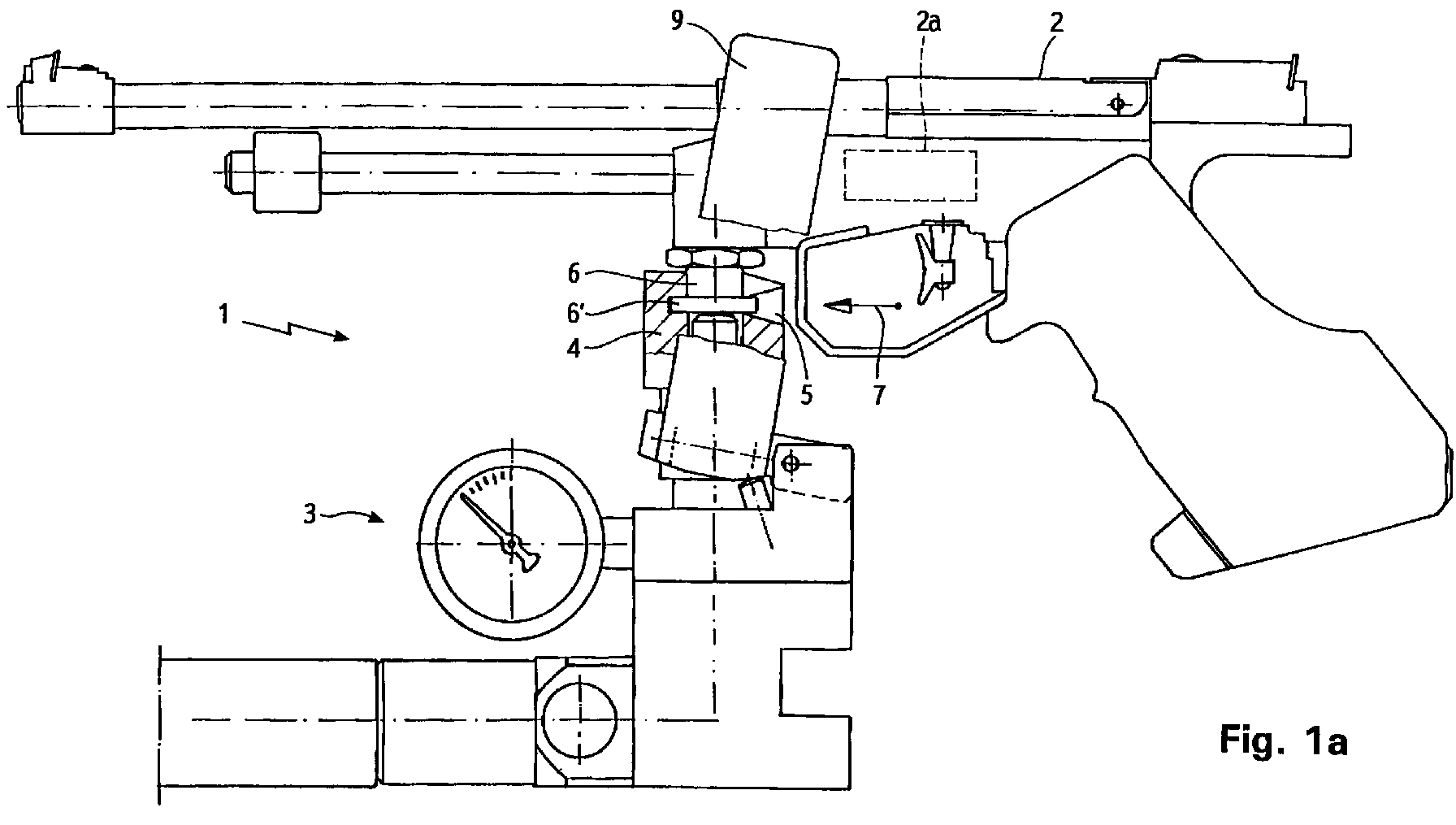
- the filling device designated by 1 in FIG. 1 serves filling a chamber 2a in a gas pressure weapon 2 and For this purpose, has a charging station 3 in which gas is stored or in connection with a corresponding gas storage facility stands.
- the charging station 3 has a filling nozzle 4 with a Recording 5 in which a suitably trained adapter 6 of the weapon 2 are inserted in the insertion direction 7 can (Fig. 1a).
- the desired one Pressure can be set in the chamber of the weapon 2.
- one of the shooters is preferably at the charging station adjustable pressure reducer provided by which when filling with compressed air compared to the pressure fed into the weapon e.g. in conventional compressed air bottles Pressure can be reduced so far that the weapon then no own pressure reducer needed.
- FIG. 2 shows a further exemplary embodiment of a filling device 1 ', in which the charging station 3' with a quick fastener 14 'for securing the adapter 6' is provided on the filling nozzle 4 'of the charging station 3'.
- the charging station 3' with a quick fastener 14 'for securing the adapter 6' is provided on the filling nozzle 4 'of the charging station 3'.
- a pair of pawls 15' of the quick release 14 ' engages behind the adapter 6' (Fig. 2b).
- the Pawl pair 15 ' is in a control contour 16' of the lever 9 ' guided and pressurized against the direction of insertion 7 '.
- the lever 9 ' is in turn opposed by two the arrow direction 7 'spring-loaded pressure pin 17' applied to its initial position (Fig. 2a).
Landscapes
- Engineering & Computer Science (AREA)
- General Engineering & Computer Science (AREA)
- Filling Or Discharging Of Gas Storage Vessels (AREA)
Abstract
Eine Vorrichtung (1) zum Befüllen einer Kammer (2a) in einer
Gasdruckwaffe (2) mit Gas, insbesondere mit CO2 oder Druckluft,
weist eine separate Ladestation (3), in der Gas bevorratet
ist, einen mit der Kammer (2a) in Verbindung stehenden
Adapter (6) an der Waffe (2), mit dem die Waffe (2) zum Befüllen
der Kammer (2a) an die Ladestation (3) anschließbar
ist, und ein betätigbares Ventil an der Ladestation (3) auf,
durch dessen Betätigung die Kammer (2a) über den Adapter (6)
mit Gas aus der Ladestation (3) befüllbar ist. So kann der
Schütze von Schuß zu Schuß seine Waffe einfach mit der Ladestation
verbinden und hat dann jeweils in der Kammer (2a)
der Waffe ausreichend Energie entweder für nur den nächsten
Schuß oder für mehrere Schüsse getankt.
Description
Die Erfindung betrifft eine Vorrichtung zum Befüllen einer Kammer in einer Gasdruck-Wettkampfwaffe mit Gas, insbesondere mit vorzugsweise flüssigem CO2 oder Preßluft.The invention relates to a device for filling a chamber in a gas pressure competition weapon with gas, in particular with preferably liquid CO 2 or compressed air.
Bekannte Gasdruckwaffen, wie sie bei Sportwettkämpfen eingesetzt werden, z.B. CO2- bzw. Preßluftwaffen, haben, abgesehen von Kompressionsmodellen und federgetriebenen Modellen, einen Vorratsbehälter für eine bestimmte Anzahl von Schüssen. Das Nachfüllen des Vorratsbehalters aus größeren Gasflaschen oder Preßluftflaschen gestaltet sich jedoch immer etwas schwierig und ist in der Regel meist unangenehm, wenn man sich entscheidet, zum Schießen zu gehen, und feststellen muß, daß der Vorratsbehälter nicht mehr ausreichend gefüllt ist. Dadurch, daß der Vorratsbehälter an der Waffe angebracht ist, erhöht sich weiterhin das Waffengewicht. Auch ist die Konstruktionsmöglichkeit ziemlich eingeschränkt, da z.B. bei Preßluftwaffen ein Druckminderer zwischen Vorratsbehälter und einer Zwischenkammer, die bei der Schußabgabe über ein Ventil beim Abziehen entleert wird, geschaltet sein muß. Auch sind die Bevorratung, das Füllen des an der Waffe befindlichen Vorratsbehälters sowie die anschließende Kontrolle der benötigten Kleinmenge an Gas zur Zeit sehr aufwendig. Als Beispiel sei hier CO2 genannt: Beim Abfüllen von CO2 muß darauf geachtet werden, daß beim Abfüllvorgang der Vorratsbehälter kalt ist und nur flüssiges CO2 aus einer separaten Vorratsflasche in den Vorratsbehälter entnommen wird. Danach muß der Vorratsbehälter gewogen und eventuell überschüssiges CO2 abgelassen werden, damit keine Überfüllung stattfindet.Known gas pressure weapons, such as those used in sports competitions, for example CO 2 or compressed air weapons, have, apart from compression models and spring-driven models, a storage container for a certain number of shots. Refilling the storage container from larger gas bottles or compressed air bottles is always a bit difficult and is usually usually uncomfortable when you decide to go shooting and find that the storage container is no longer sufficiently filled. Because the storage container is attached to the weapon, the weapon weight continues to increase. The design option is also quite limited, since, for example in the case of compressed air weapons, a pressure reducer must be connected between the storage container and an intermediate chamber, which is emptied when the shot is fired via a valve when it is pulled off. The stockpiling, the filling of the storage container on the weapon and the subsequent control of the required small amount of gas are also very time-consuming. One example is CO 2 : When filling CO 2 , make sure that the storage container is cold during the filling process and that only liquid CO 2 is removed from a separate storage bottle into the storage container. Then the storage container must be weighed and any excess CO 2 must be drained off so that there is no overfilling.
Der Erfindung liegt demgegenüber die Aufgabe zugrunde, bei einer Befüllungsvorrichtung der eingangs genannten Art den Befüllungsvorgang zu vereinfachen und zu erleichtern.In contrast, the invention is based on the object a filling device of the type mentioned Simplify and facilitate the filling process.
Diese Aufgabe wird bei einer Befüllungsvorrichtung der eingangs genannten Art erfindungsgemäß gelöst durch eine separate Ladestation, in der Gas bevorratet ist, einen mit der Kammer in Verbindung stehenden Adapter an der Waffe, mit dem die Waffe zum Befüllen der Kammer an die Ladestation anschließbar ist, und ein betätigbares Ventil an der Ladestation, durch dessen Betätigung die Kammer über den Adapter mit Gas aus der Ladestation befüllbar ist.This task is the beginning of a filling device mentioned type solved according to the invention by a separate Charging station in which gas is stored, one with the Chamber related adapter on the weapon with which the weapon for filling the chamber can be connected to the charging station and an actuatable valve on the charging station, by actuating the chamber via the adapter can be filled with gas from the charging station.
Bei dieser Befüllungsvorrichtung kann der Schütze von Schuß zu Schuß seine Waffe einfach mit der vorzugsweise stationären Ladestation verbinden und hat dann jeweils in der Kammer (Zwischenkammer) der Waffe ausreichend Energie entweder für nur den nächsten Schuß oder für mehrere Schüsse getankt. Er hat somit die Möglichkeit, ein längeres Trainingsprogramm zu absolvieren, und dies immer mit nahezu demselben Druck, insbesondere bei einer Befüllung mit Preßluft, da die Druckabnahme in einem größeren Vorratsbehälter der Ladestation wesentlich langsamer erfolgt als in einem normalen Preßluft-Vorratsbehälter, der herkömmlich an der Waffe angebracht ist. Das Antriebsmedium, sei es CO2 oder Preßluft, wird mittels der Ladestation Schuß für Schuß, während des Befüllungsvorgangs mit der Waffe abgenommen. Die Ladestation kann wahlweise mit Preßluft, CO2 oder einem anderen geeigneten Gas betrieben werden. Durch die Abkoppelung des Vorratsbehälters von der Waffe kann diese nun leichter ausgelegt und mehr auf den Schützen zugeschnitten werden. Dies führt zu größer Gestaltungsfreiheit beim Aufbau der Waffe bei gleichzeitiger Reduzierung des Waffengewichtes. So kann auf den Vorratsbehälter an der Waffe verzichtet werden, und muß nur bei Bedarf die Ladestation benutzt werden, um das Antriebsmedium von Schuß zu Schuß in dosierter Form in die Waffe einzubringen.In this filling device, the shooter can simply connect his weapon to the preferably stationary charging station from shot to shot and then has sufficient energy in the chamber (intermediate chamber) of the weapon either for only the next shot or for several shots. He has the opportunity to complete a longer training program, and always with almost the same pressure, especially when filling with compressed air, since the pressure decrease in a larger storage container of the charging station is much slower than in a normal compressed air storage container, which is conventional attached to the weapon. The drive medium, be it CO 2 or compressed air, is removed shot by shot by the charging station during the filling process with the weapon. The charging station can be operated with compressed air, CO 2 or another suitable gas. By uncoupling the storage container from the weapon, it can now be designed more easily and tailored more to the shooter. This leads to greater design freedom when building the weapon while reducing the weight of the weapon. Thus, the storage container on the weapon can be dispensed with, and the charging station only has to be used if necessary in order to introduce the drive medium from shot to shot in metered form into the weapon.
Der Schütze kann z.B. eine gefüllte 3-kg-Vorratsflasche Gas oder 4-Liter-Preßluftflasche als Vorratsbehälter mit zum Schützenhaus nehmen, diese unter der Waffenablage an seinem Schießstand plazieren und so, z.B. mittels einer Schlauchverbindung, zu einer Ladestation an seinem Schießstand weiterbilden, um seine Waffe jeweils durch Ankoppeln an die Ladestation, d.h. an seinen Vorratsbehälter, zu befüllen. Der Druckbehälter der Waffe kann ebenso bei einer solchen Befüllungseinrichtung eingesetzt werden.The shooter can e.g. a filled 3 kg gas bottle or 4 liter compressed air bottle as a storage container with for Take rifle house, this under the weapon rack on his Place the shooting range and so, e.g. by means of a hose connection, train to a charging station at his shooting range, around his weapon by coupling to the charging station, i.e. to fill his reservoir. Of the Pressure vessels of the weapon can also be used with such a filling device be used.
Damit die Waffe mit reproduzierbarem Druck befüllt werden kann, ist der Adapter vorzugsweise während des Befüllungsvorgangs in der Ladestation zentriert bzw. zur Befüllungsöffnung der Ladestation zentriert angeordnet. So that the weapon can be filled with reproducible pressure can, the adapter is preferably during the filling process centered in the charging station or to the filling opening the charging station is centered.
Da das Gas (Antriebsmedium) unter Druck aus der Ladestation in die Kammer der Waffe einströmt, ist es von Vorteil, wenn der Adapter während des Befüllungsvorgangs mittels eines Schnellverschlusses an der Ladestation gesichert ist. Dieser Schnellverschluß, z.B. ein Bajonett- oder Linearverschluß oder eine sonstige Kupplung, befindet sich z.B. an der Ladestation, während der Adapter an der Waffe dementsprechend ausgeführt ist.Because the gas (drive medium) is under pressure from the charging station flows into the chamber of the weapon, it is advantageous if the adapter during the filling process by means of a Quick release is secured to the charging station. This Quick release, e.g. a bayonet or linear lock or another clutch, is e.g. at the charging station, while the adapter on the weapon accordingly is executed.
Der Schnellverschluß und das Ventil können getrennt voneinander elektrisch oder mechanisch betätigt werden. Jedoch ist bevorzugt, daß das Ventil der Ladestation mit dem Schnellverschluß und/oder mit der Zentrierung mechanisch gekoppelt ist, so daß nur ein Handgriff zur Betätigung beider Funktionen erforderlich ist.The quick release and the valve can be separated from each other be operated electrically or mechanically. However is preferred that the valve of the charging station with the quick release and / or mechanically coupled to the centering is, so that only one handle to operate both functions is required.
Bei bevorzugten Ausführungsformen der Erfindung ist das Ventil durch eine Bewegung eines Befüllungsstutzens, an dem der Adapter anliegt, betätigbar. Dafür kann eine den Befüllungsstutzen in seine das Ventil betätigende Stellung kraftbeaufschlagende Handhabe, insbesondere ein verschwenkbarer Hebel, vorgesehen sein. Die Handhabe kann auch zum Verriegeln des Schnellverschlusses dienen, der durch eine Bewegung der Handhabe in die entgegengesetzte Richtung wieder geöffnet wird.In preferred embodiments of the invention, the valve is by moving a filler neck on which the Adapter is present, can be actuated. One can use the filler neck for this in its position actuating the valve Handle, in particular a pivotable lever, be provided. The handle can also be used to lock the Serve quick release by moving the Handle opened again in the opposite direction becomes.
Um den Adapter an der Ladestation an definierter Stelle anbringen zu können, ist vorzugsweise an der Ladestation eine Aufnahme für den Adapter vorgesehen.To attach the adapter to the charging station at a defined location to be able to, is preferably at the charging station Support for the adapter provided.
Wenn auch die zu befüllende Kammer am Adapter lösbar gehalten ist, ergibt sich der Vorteil, daß je nach Bedarf Kammern mit Gasvorrat für nur einen oder mehrere Schüsse an den Adapter angebracht werden können.If the chamber to be filled is held releasably on the adapter is, there is the advantage that chambers as required with gas supply for just one or more shots at the adapter can be attached.
Vorzugsweise sind der Adapter und die Kammer bereits an der Waffe integriert ausgebildet.Preferably, the adapter and the chamber are already on the Integrated weapon design.
Um auch herkömmliche Gasdruckwaffen mit möglichst wenig nachträglichem Aufwand an die erfindungsgemäße Befüllungsvorrichtung anschließen zu können, kann der Adapter z.B. anstelle eines ansonsten vorgesehenen Gas-Vorratsbehälters in eine entsprechende Öffnung in der Waffe eingebaut sein. Dadurch verringert sich außerdem das Waffengewicht um das Differenzgewicht von Vorratsbehälter und Adapter.To even conventional gas pressure weapons with as little as possible subsequent effort to the filling device according to the invention to be able to connect, the adapter can e.g. instead of of an otherwise provided gas storage container in a corresponding opening must be built into the weapon. Thereby the weapon weight is also reduced by the differential weight of storage container and adapter.
Die Erfindung betrifft auch ein zentrales Befüllungssystem mit einem zentralen Gas-Vorratsspeicher und mit mindestens zwei, jeweils an den zentralen Gas-Vorratsspeicher angeschlossenen Befüllungsvorrichtungen, wie sie oben beschrieben sind. Durch Abzweigungen von einer größeren Vorratsflasche können mehrere, z.B. drei oder vier, Ladestationen verbunden werden, so daß mehrere Schützen ihre Waffen direkt aus dieser Vorratsflasche auftanken können. Bei größeren Vereinen und Veranstaltungen ist es so möglich, über eine Zentralversorgung alle Schützen mit entsprechenden Treibmitteln (CO2 und/oder Preßluft) über die jeweiligen Ladestationen zu versorgen.The invention also relates to a central filling system with a central gas storage tank and with at least two filling devices, each connected to the central gas storage tank, as described above. By branching off a larger storage bottle, several, for example three or four, charging stations can be connected, so that several shooters can refuel their weapons directly from this storage bottle. For larger clubs and events, it is possible to supply all shooters with appropriate propellants (CO 2 and / or compressed air) via the respective charging stations via a central supply.
Weitere Vorteile der Erfindung ergeben sich aus der Beschreibung und der Zeichnung. Ebenso können die vorstehend genannten und die noch weiter aufgeführten Merkmale erfindungsgemäß jeweils einzeln für sich oder zu mehreren in beliebigen Kombinationen Verwendung finden. Die gezeigten und beschriebenen Ausführungsformen sind nicht als abschließende Aufzählung zu verstehen, sondern haben vielmehr beispielhaften Charakter für die Schilderung der Erfindung.Further advantages of the invention result from the description and the drawing. Likewise, the above mentioned and the features listed further according to the invention individually for themselves or for several in any Combinations are used. The shown and The embodiments described are not intended to be final Understand enumeration, but rather have exemplary Character for the description of the invention.
Es zeigt:
- Fig. 1a
- ein erstes Ausführungsbeispiel einer erfindungsgemäßen Befüllungsvorrichtung in ihrer Einführ- bzw. Entnahmestellung;
- Fig. 1b
- die Befüllungsvorrichtung der Fig. 1a in ihrer Befüllungsstellung;
- Fig. 2a
- ein zweites Ausführungsbeispiel einer erfindungsgemäßen Befüllungsvorrichtung in ihrer Einführstellung;
- Fig. 2b
- in einer teilweise geschnittenen Ansicht ein Detail der Befüllungsvorrichtung der Fig. 2a im Anschlußbereich eines Befüllungsstutzen der Ladestation und eines entsprechenden Adapters an der Waffe;
- Fig. 2c
- die Befüllungsvorrichtung der Fig. 2a in ihrer Befüllungsstellung; und
- Fig. 2d
- die Befüllungsvorrichtung der Fig. 2a in ihrer Entnahmestellung.
- Fig. 1a
- a first embodiment of a filling device according to the invention in its insertion or removal position;
- Fig. 1b
- the filling device of Figure 1a in its filling position.
- Fig. 2a
- a second embodiment of a filling device according to the invention in its insertion position;
- Fig. 2b
- in a partially sectioned view a detail of the filling device of FIG. 2a in the connection area of a filling nozzle of the charging station and a corresponding adapter on the weapon;
- Fig. 2c
- the filling device of Figure 2a in its filling position. and
- Fig. 2d
- the filling device of Fig. 2a in its removal position.
Die in Fig. 1 mit 1 bezeichnete Befüllungsvorrichtung dient
dem Befüllen einer Kammer 2a in einer Gasdruckwaffe 2 und
weist dazu eine Ladestation 3 auf, in der Gas bevorratet ist
oder mit einem entsprechenden Gas-Vorratsspeicher in Verbindung
steht. The filling device designated by 1 in FIG. 1 serves
filling a
Die Ladestation 3 weist einen Befüllungsstutzen 4 mit einer
Aufnahme 5 auf, in die ein entsprechend ausgebildeter Adapter
6 der Waffe 2 in Einführrichtung 7 eingeschoben werden
kann (Fig. 1a).The charging
Durch Verschwenken eines an der Ladestation 3 bei 8 gelagerten
Hebels 9 (Fig. 1b) wird der Befüllungsstutzen 4 axial
nach unten gedrückt und über einen Bolzen 11 gefahren, der
den Adapter 6 in der Aufnahme 5 verriegelt und zentriert;
dabei gewährleistet ein am Adapter 6 vorhandener nach außen
ragender Vorsprung 6', der in eine Nut des Befüllungsstutzens
4 eingreift, die Verbindung in Längsrichtung des Bolzens
11. Gleichzeitig wird gegen die Wirkung einer Rückstellkraft
ein an der Ladestation 3 befindlicher Stift 12
durch den Hebel 9 zurückgedrückt. Das Ventil (nicht dargestellt)
in der Ladestation 3 wird durch die Abwärtsbewegung
des Befüllstutzens 4 geöffnet, und die Kammer 2a der Waffe 2
wird über den Adapter 6 mit Gas aus der Ladestation 3 befüllt.
Über ein Manometer 13 der Ladestation 3 kann der gewünschte
Druck in der Kammer der Waffe 2 eingestellt werden.
Hierzu ist an der Ladestation vorzugsweise ein vom Schützen
verstellbarer Druckminderer vorgesehen, durch den beim Füllen
mit Druckluft der in die Waffe eingespeiste Druck gegenüber
dem z.B. in herkömmlichen Preßluftflaschen herschenden
Druck so weit vermindert werden kann, daß die Waffe dann
keinen eigenen Druckminderer benötigt.By pivoting one stored at 8 at the charging
Danach wird der Hebel 9 in entgegengesetzter Richtung in die
in Fig. 1a gezeigte Stellung zurückgeschwenkt, wodurch die
Verriegelung durch den Bolzen 11 gelöst und der Stift 12
aufgrund der Rückstellkraft wieder in seine Ausgangsstellung
ausfährt, d.h., der Stift 12 ist für die Grundstellung verantwortlich.
Das Ventil in der Ladestation 3 schließt, der
Befüllungsvorgang ist beendet, und die Waffe 2 kann nun aus
dem Befüllungsstutzen 4 entnommen werden.Then the
In der Fig. 2 ist ein weiteres Ausführungsbeispiel einer Befüllungsvorrichtung 1' gezeigt, bei der die Ladestation 3' mit einem Schnellverschluß 14' zum Sichern des Adapters 6' am Befüllungsstutzen 4' der Ladestation 3' versehen ist. Der Adapter 6' wird in Pfeilrichtung 7' an den Befüllungsstutzen 4' angesetzt, wobei ein Klinkenpaar 15' des Schnellverschlusses 14' den Adapter 6' hintergreift (Fig. 2b). Das Klinkenpaar 15' ist in einer Steuerkontur 16' des Hebels 9' geführt und entgegen der Einführrichtung 7' druckbeaufschlagt. Der Hebel 9' ist seinerseits mittels zweier, entgegen der Pfeilrichtung 7' federbeaufschlagter Druckbolzen 17' in seine Anfangsstellung (Fig. 2a) beaufschlagt.2 shows a further exemplary embodiment of a filling device 1 ', in which the charging station 3' with a quick fastener 14 'for securing the adapter 6' is provided on the filling nozzle 4 'of the charging station 3'. Of the Adapter 6 'is in the direction of arrow 7' on the filler neck 4 'attached, with a pair of pawls 15' of the quick release 14 'engages behind the adapter 6' (Fig. 2b). The Pawl pair 15 'is in a control contour 16' of the lever 9 ' guided and pressurized against the direction of insertion 7 '. The lever 9 'is in turn opposed by two the arrow direction 7 'spring-loaded pressure pin 17' applied to its initial position (Fig. 2a).
Indem bei am Befüllungsstutzen 4' anliegendem Adapter der Hebel 9' um seinen Lagerpunkt 8' in Drehrichtung 10' verschwenkt wird (Fig. 2c), wird zunächst das Klinkenpaar 15' aufgrund der Steuerkontur 16' in seine den Adapter 6' hintergreifende, verriegelnde Stellung gebracht (Fig. 2b) und entsprechend dem Ausführungsbeispiel in Fig. 1 das Ventil der Ladestation 3' geöffnet.By the at the filling nozzle 4 'adjacent adapter Lever 9 'pivoted about its bearing point 8' in the direction of rotation 10 ' (Fig. 2c), the pair of jacks 15 ' due to the control contour 16 'in its behind the adapter 6', locking position brought (Fig. 2b) and corresponding to the embodiment in Fig. 1, the valve the charging station 3 'opened.
Nach Abschluß des Befüllungsvorgangs wird der Hebel 9' in
entgegengesetzter Richtung über die in Fig. 2a gezeigte Anfangsstellung
hinaus zurückgeschwenkt (Fig. 2d), wodurch das
Klinkenpaar 15' in Pfeilrichtung 18' ausfahren und in eine
den Adapter 6' freigebende Stellung aufschwenken kann. Die
Waffe 2 kann nun von der Ladestation 3' in Pfeilrichtung 18'
abgenommen werden.After completion of the filling process, the lever 9 'in
opposite direction over the initial position shown in Fig. 2a
pivoted back (Fig. 2d), which the
Extend pair of pawls 15 'in the direction of arrow 18' and into one
the adapter 6 'release position. The
Claims (13)
Applications Claiming Priority (2)
| Application Number | Priority Date | Filing Date | Title |
|---|---|---|---|
| DE19745703 | 1997-10-16 | ||
| DE19745703A DE19745703A1 (en) | 1997-10-16 | 1997-10-16 | Filling device for gas pressure weapons |
Publications (2)
| Publication Number | Publication Date |
|---|---|
| EP0909936A2 true EP0909936A2 (en) | 1999-04-21 |
| EP0909936A3 EP0909936A3 (en) | 1999-12-01 |
Family
ID=7845707
Family Applications (1)
| Application Number | Title | Priority Date | Filing Date |
|---|---|---|---|
| EP98119565A Withdrawn EP0909936A3 (en) | 1997-10-16 | 1998-10-16 | Device for filling air guns |
Country Status (2)
| Country | Link |
|---|---|
| EP (1) | EP0909936A3 (en) |
| DE (1) | DE19745703A1 (en) |
Cited By (2)
| Publication number | Priority date | Publication date | Assignee | Title |
|---|---|---|---|---|
| US6732726B2 (en) * | 2002-08-28 | 2004-05-11 | Avalon Manufacturing Company | Paint ball gun having a front mounted gas cylinder |
| US7318428B2 (en) | 2002-04-05 | 2008-01-15 | Avalon Advanced Products, Inc. | Paint ball gun having paint ball dispenser with threaded connector |
Family Cites Families (6)
| Publication number | Priority date | Publication date | Assignee | Title |
|---|---|---|---|---|
| DE232854C (en) * | ||||
| FR879387A (en) * | 1941-03-05 | 1943-02-22 | Air rifle shooting range | |
| DE934995C (en) * | 1952-04-09 | 1955-11-10 | Heikki Eino Klemola | Valve arrangement for a compressed air gun |
| DE2602455A1 (en) * | 1976-01-23 | 1977-08-04 | Kullmann Geb Biehler Luise Car | Gun for shooting darts esp. into animals - has variable pressure gas reservoir as power source |
| DE2731853C2 (en) * | 1977-07-14 | 1982-05-13 | Carl Walther Gmbh, 7900 Ulm | Air gun |
| JP2597829B2 (en) * | 1995-04-05 | 1997-04-09 | 株式会社ウエスタン・アームス | Gas accumulator supply device |
-
1997
- 1997-10-16 DE DE19745703A patent/DE19745703A1/en not_active Withdrawn
-
1998
- 1998-10-16 EP EP98119565A patent/EP0909936A3/en not_active Withdrawn
Cited By (3)
| Publication number | Priority date | Publication date | Assignee | Title |
|---|---|---|---|---|
| US7318428B2 (en) | 2002-04-05 | 2008-01-15 | Avalon Advanced Products, Inc. | Paint ball gun having paint ball dispenser with threaded connector |
| US7775199B2 (en) | 2002-04-05 | 2010-08-17 | Avalon Advanced Products, Inc. | Paint ball gun having paint ball dispenser with threaded connector |
| US6732726B2 (en) * | 2002-08-28 | 2004-05-11 | Avalon Manufacturing Company | Paint ball gun having a front mounted gas cylinder |
Also Published As
| Publication number | Publication date |
|---|---|
| EP0909936A3 (en) | 1999-12-01 |
| DE19745703A1 (en) | 1999-04-22 |
Similar Documents
| Publication | Publication Date | Title |
|---|---|---|
| DE68914004T2 (en) | Pressure regulator for a surgical stapling instrument. | |
| DE2601901A1 (en) | METHOD AND DEVICE FOR DISPLACING A LIQUID FROM A PIPELINE IN WATER AND CHECKING THE INSIDE OF THE PIPELINE | |
| AT16556U1 (en) | Firearm for temporary conversion into a firearm simulator | |
| DE2029410A1 (en) | Automatic firearm | |
| DE3505443A1 (en) | AIR PRESSURE ARMS | |
| DE2812759B2 (en) | Trigger device for a revolver | |
| DE10127379A1 (en) | Air gun trigger system has holder triggered to release firing system from ready state by either trigger device with driving unit causing continuous movement of other trigger device for fully automatic firing | |
| DE3235918C2 (en) | ||
| DE4133618C2 (en) | Ejector system for barrel weapons | |
| DE102015006801B3 (en) | Loading aid for magazines | |
| DE3434966C2 (en) | ||
| DE19745703A1 (en) | Filling device for gas pressure weapons | |
| DE202018105702U1 (en) | Shooting device of a toy gun | |
| DE3035796C2 (en) | ||
| DE3530212C1 (en) | Device for delivering a pasty product | |
| DE2640842A1 (en) | Acetylene bottle filling system - with common valve for jointly filled batch controlled by weighing one bottle | |
| DE69805746T2 (en) | CONTAINER FOR STORING AND LOCKING A TORPEDO | |
| DE725659C (en) | Device for transferring pressurized gases or liquid gases | |
| DE2602455A1 (en) | Gun for shooting darts esp. into animals - has variable pressure gas reservoir as power source | |
| DE607587C (en) | Firearm with exchangeable barrel | |
| DE3616990C1 (en) | Air blast device for resolving material build-up in storage silos for bulk material | |
| EP1377787B1 (en) | Compressed gas-driven gun device and compressed gas supply device for such a gun device | |
| DE3046289C2 (en) | Dosing device, in particular for mineral oil products | |
| DE1966147A1 (en) | Fixed barrel spring compressed air rifle | |
| DE2824635A1 (en) | PRESSURE ACTUATED SUPPORT STRUT |
Legal Events
| Date | Code | Title | Description |
|---|---|---|---|
| PUAI | Public reference made under article 153(3) epc to a published international application that has entered the european phase |
Free format text: ORIGINAL CODE: 0009012 |
|
| AK | Designated contracting states |
Kind code of ref document: A2 Designated state(s): AT BE CH CY DE DK ES FI FR GB GR IE IT LI LU MC NL PT SE |
|
| AX | Request for extension of the european patent |
Free format text: AL;LT;LV;MK;RO;SI |
|
| PUAL | Search report despatched |
Free format text: ORIGINAL CODE: 0009013 |
|
| AK | Designated contracting states |
Kind code of ref document: A3 Designated state(s): AT BE CH CY DE DK ES FI FR GB GR IE IT LI LU MC NL PT SE |
|
| AX | Request for extension of the european patent |
Free format text: AL;LT;LV;MK;RO;SI |
|
| RIC1 | Information provided on ipc code assigned before grant |
Free format text: 6F 41B 11/06 A, 6F 41B 11/28 B |
|
| AKX | Designation fees paid | ||
| REG | Reference to a national code |
Ref country code: DE Ref legal event code: 8566 |
|
| STAA | Information on the status of an ep patent application or granted ep patent |
Free format text: STATUS: THE APPLICATION IS DEEMED TO BE WITHDRAWN |
|
| 18D | Application deemed to be withdrawn |
Effective date: 20000603 |