EP0909934A2 - Method for cleaning water heating elements, in particular armoured resistance elements - Google Patents
Method for cleaning water heating elements, in particular armoured resistance elements Download PDFInfo
- Publication number
- EP0909934A2 EP0909934A2 EP98119206A EP98119206A EP0909934A2 EP 0909934 A2 EP0909934 A2 EP 0909934A2 EP 98119206 A EP98119206 A EP 98119206A EP 98119206 A EP98119206 A EP 98119206A EP 0909934 A2 EP0909934 A2 EP 0909934A2
- Authority
- EP
- European Patent Office
- Prior art keywords
- elements
- water heating
- cleaning
- cleaning water
- heating elements
- Prior art date
- Legal status (The legal status is an assumption and is not a legal conclusion. Google has not performed a legal analysis and makes no representation as to the accuracy of the status listed.)
- Withdrawn
Links
- 238000004140 cleaning Methods 0.000 title claims abstract description 17
- 238000000034 method Methods 0.000 title claims abstract description 14
- XLYOFNOQVPJJNP-UHFFFAOYSA-N water Substances O XLYOFNOQVPJJNP-UHFFFAOYSA-N 0.000 title claims abstract description 8
- 238000010438 heat treatment Methods 0.000 title claims abstract description 6
- 238000005299 abrasion Methods 0.000 claims abstract 2
- 239000000835 fiber Substances 0.000 claims description 2
- 235000013311 vegetables Nutrition 0.000 claims description 2
- 238000005498 polishing Methods 0.000 description 4
- CPLXHLVBOLITMK-UHFFFAOYSA-N magnesium oxide Inorganic materials [Mg]=O CPLXHLVBOLITMK-UHFFFAOYSA-N 0.000 description 2
- 239000000395 magnesium oxide Substances 0.000 description 2
- AXZKOIWUVFPNLO-UHFFFAOYSA-N magnesium;oxygen(2-) Chemical compound [O-2].[Mg+2] AXZKOIWUVFPNLO-UHFFFAOYSA-N 0.000 description 2
- 239000007787 solid Substances 0.000 description 2
- 235000008733 Citrus aurantifolia Nutrition 0.000 description 1
- 229910000831 Steel Inorganic materials 0.000 description 1
- 235000011941 Tilia x europaea Nutrition 0.000 description 1
- 239000003082 abrasive agent Substances 0.000 description 1
- 239000002253 acid Substances 0.000 description 1
- 150000007513 acids Chemical class 0.000 description 1
- 238000005260 corrosion Methods 0.000 description 1
- 230000007797 corrosion Effects 0.000 description 1
- 238000005238 degreasing Methods 0.000 description 1
- 239000003599 detergent Substances 0.000 description 1
- 239000003989 dielectric material Substances 0.000 description 1
- 238000003912 environmental pollution Methods 0.000 description 1
- 239000004571 lime Substances 0.000 description 1
- 239000007788 liquid Substances 0.000 description 1
- 238000012423 maintenance Methods 0.000 description 1
- 230000003647 oxidation Effects 0.000 description 1
- 238000007254 oxidation reaction Methods 0.000 description 1
- 238000002360 preparation method Methods 0.000 description 1
- 238000000746 purification Methods 0.000 description 1
- 239000010959 steel Substances 0.000 description 1
- 239000000126 substance Substances 0.000 description 1
- 229920002994 synthetic fiber Polymers 0.000 description 1
Images
Classifications
-
- F—MECHANICAL ENGINEERING; LIGHTING; HEATING; WEAPONS; BLASTING
- F28—HEAT EXCHANGE IN GENERAL
- F28G—CLEANING OF INTERNAL OR EXTERNAL SURFACES OF HEAT-EXCHANGE OR HEAT-TRANSFER CONDUITS, e.g. WATER TUBES OR BOILERS
- F28G3/00—Rotary appliances
- F28G3/04—Rotary appliances having brushes
-
- F—MECHANICAL ENGINEERING; LIGHTING; HEATING; WEAPONS; BLASTING
- F24—HEATING; RANGES; VENTILATING
- F24H—FLUID HEATERS, e.g. WATER OR AIR HEATERS, HAVING HEAT-GENERATING MEANS, e.g. HEAT PUMPS, IN GENERAL
- F24H9/00—Details
- F24H9/0005—Details for water heaters
- F24H9/0042—Cleaning arrangements
Definitions
- This invention relates to a method for cleaning water heating elements, in particular armoured resistance elements.
- Water heating elements consisting substantially of a steel sheath internally housing a resistive wire separated from the sheath by a dielectric substance, in particular magnesium oxide.
- the sheath In order to free the surface of the sheath from oxidation and irregularities which could allow the detergent and lime to accumulate with resultant corrosion, the sheath is subjected to finishing treatment generally consisting of polishing in an electrolytic bath.
- the resistance element is washed with hot water, possibly slightly alkaline, to neutralize the residual bath acids.
- An object of the invention is to eliminate these drawbacks by providing a method which enables the resistance element to be cleaned in a completely automated manner, is of high productivity and low cost, requires little maintenance, and suffers from no ecological problems.
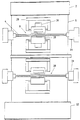
- the plant for implementing the method of the invention comprises substantially a loading hopper 2 housing the individual resistance elements 4 already assembled, ie with the resistive wire inserted into the sheath and separated therefrom by dielectric material, for example magnesium oxide.
- a conveyor 6 for conveying the individual resistance elements to a cleaning station 8 and a polishing station 10.
- the conveyor exit is connected to a discharge hopper 12.
- the cleaning station 8 and polishing station 10 comprise two chucks 14 for locking the resistance element and two vegetable fibre brushes 16 of horizontal axis, each of which is faced by a cake of abrasive paste.
- the brushes are mounted on a traversable frame 20.
- an individual resistance element 4 is discharged by the loading hopper 2 onto the conveyor 6 to be fed to the cleaning station 8, where it is locked by the locking chucks 14.
- the brushes 16 are operated so that as a result of their rotation the fibres pick up abrasive paste while at the same time mechanically cleaning the resistance element.
- the brushes are made to traverse along their axis so as to clean the entire resistance element.
- the resistance element is then conveyed to the polishing station where the aforedescribed operations are effected. After cleaning, the resistance element is fed to the discharge hopper 12.
- the described example relates to a plant operating automatically on a straight resistance element.
- the method can however also be carried out manually, ie by subjecting the individual resistance elements to a manual mechanical cleaning operation. It can also be used manually or automatically on an already completed resistance element.
Landscapes
- Engineering & Computer Science (AREA)
- Chemical & Material Sciences (AREA)
- Combustion & Propulsion (AREA)
- Mechanical Engineering (AREA)
- General Engineering & Computer Science (AREA)
- Physics & Mathematics (AREA)
- Thermal Sciences (AREA)
- Cleaning In General (AREA)
- Resistance Heating (AREA)
- Bidet-Like Cleaning Device And Other Flush Toilet Accessories (AREA)
- Cleaning By Liquid Or Steam (AREA)
Abstract
Description
- high cost due to the provision of the electrolytic plant itself and the need to provide a wash water purification plant and a bath liquid disposal plant,
- low productivity,
- laborious preparation of the resistance element for the electrocleaning, requiring precleaning and degreasing of any fingerprints which, following electrocleaning, would be highlighted and indelibly impressed on the resistance element,
- incomplete cleaning as the sheath requires protection of its ends, which hence remain uncleaned.
- it is lower cost than the electrocleaning plant,
- there are no environmental pollution problems, as the solid residues are discharged as solid urban refuse,
- it enables reliable finishing to be achieved by the use of synthetic fibres and abrasive material which is continuously replaced,
- it is suitable for automation, with consequent high productivity.
Claims (3)
- A method for cleaning water heating elements, in particular armoured resistance elements, characterised in that the cleaning is carried out by mechanical abrasion.
- A method as claimed in claim 1, characterised in that the cleaning is carried out with rotating brushes of vegetable fibre.
- A method as claimed in claim 1, characterised in that the rotating brushes are faced by a cake of abrasive paste.
Applications Claiming Priority (2)
| Application Number | Priority Date | Filing Date | Title |
|---|---|---|---|
| ITVE970045 | 1997-10-17 | ||
| IT97VE000045A IT1297494B1 (en) | 1997-10-17 | 1997-10-17 | CLEANING PROCEDURE FOR WATER HEATING ELEMENTS, IN PARTICULAR ARMORED RESISTORS. |
Publications (2)
| Publication Number | Publication Date |
|---|---|
| EP0909934A2 true EP0909934A2 (en) | 1999-04-21 |
| EP0909934A3 EP0909934A3 (en) | 2000-05-31 |
Family
ID=11424315
Family Applications (1)
| Application Number | Title | Priority Date | Filing Date |
|---|---|---|---|
| EP98119206A Withdrawn EP0909934A3 (en) | 1997-10-17 | 1998-10-12 | Method for cleaning water heating elements, in particular armoured resistance elements |
Country Status (2)
| Country | Link |
|---|---|
| EP (1) | EP0909934A3 (en) |
| IT (1) | IT1297494B1 (en) |
Cited By (1)
| Publication number | Priority date | Publication date | Assignee | Title |
|---|---|---|---|---|
| CN106352540A (en) * | 2015-07-21 | 2017-01-25 | 中山市元亨家居用品有限公司 | Water heater with self-cleaning function |
Family Cites Families (4)
| Publication number | Priority date | Publication date | Assignee | Title |
|---|---|---|---|---|
| DE204479C (en) * | ||||
| SE8800882L (en) * | 1988-03-11 | 1989-09-12 | Sical Ab | PROCEDURE AND DEVICE FOR EXPLORING HEATING ENERGY FROM POLLUTANEATED WATER |
| FR2655886B1 (en) * | 1989-12-20 | 1996-06-14 | Stein Industrie | APPARATUS FOR CLEANING THE EXTERNAL AND POSSIBLY INTERNAL SURFACES OF LOW DIAMETER TUBES. |
| JPH0824951B2 (en) * | 1991-12-12 | 1996-03-13 | 日本軽金属株式会社 | Hot rolling method for aluminum slabs |
-
1997
- 1997-10-17 IT IT97VE000045A patent/IT1297494B1/en active IP Right Grant
-
1998
- 1998-10-12 EP EP98119206A patent/EP0909934A3/en not_active Withdrawn
Cited By (1)
| Publication number | Priority date | Publication date | Assignee | Title |
|---|---|---|---|---|
| CN106352540A (en) * | 2015-07-21 | 2017-01-25 | 中山市元亨家居用品有限公司 | Water heater with self-cleaning function |
Also Published As
| Publication number | Publication date |
|---|---|
| IT1297494B1 (en) | 1999-12-17 |
| ITVE970045A0 (en) | 1997-10-17 |
| EP0909934A3 (en) | 2000-05-31 |
| ITVE970045A1 (en) | 1999-04-17 |
Similar Documents
| Publication | Publication Date | Title |
|---|---|---|
| CN106975632A (en) | A kind of cleaning device for auto parts machinery | |
| EP0909934A2 (en) | Method for cleaning water heating elements, in particular armoured resistance elements | |
| CN109877092B (en) | Surface cleaning system and surface treatment method for metal strip after sand blasting cleaning | |
| CN208810726U (en) | Full automatic lens cleaning machine | |
| EP1005926A3 (en) | Process and apparatus for cleaning metal strip | |
| CN215036352U (en) | Clean recovery unit for recovering aluminum | |
| CN115739850B (en) | Unqualified welding rod surface coating clearing device | |
| CN112777239B (en) | Multipurpose gearbox for conveyor belt | |
| CN114952453B (en) | Centerless grinder manipulator device | |
| CN105665327A (en) | Continuous cleaning method and device thereof | |
| CN212265490U (en) | Polishing device for special-shaped ice cream sticks | |
| CN215654174U (en) | Grid cleaning device of rotary grid dirt remover | |
| CN210538504U (en) | Automatic sweep egg liquid machine | |
| CN211359911U (en) | Oil scraping device of full-automatic tray pouring machine | |
| CN209849405U (en) | Surface cleaning system for metal strip subjected to sand blasting cleaning | |
| CN220806480U (en) | Dust-proof feeding mechanism of centerless lathe for round steel production | |
| CN214555629U (en) | Automatic cleaning device for oil stains on surface of nut | |
| CN220563628U (en) | Cleaning device for conveyor belt | |
| CN220371663U (en) | Greasy dirt removing device for fastener | |
| CN223684034U (en) | Metal material surface cleaning device | |
| CN222829210U (en) | Reverse fishing type grid bar rotary grid dirt remover with cleaning mechanism | |
| CN218133655U (en) | Belt cleaning device is used in metal product processing | |
| CN219170319U (en) | Cooling device of numerical control machine tool | |
| CN222627333U (en) | Part conveying device for machining | |
| CN216470523U (en) | Belt conveyer |
Legal Events
| Date | Code | Title | Description |
|---|---|---|---|
| PUAI | Public reference made under article 153(3) epc to a published international application that has entered the european phase |
Free format text: ORIGINAL CODE: 0009012 |
|
| AK | Designated contracting states |
Kind code of ref document: A2 Designated state(s): AT BE CH CY DE DK ES FI FR GB GR IE IT LI LU MC NL PT SE |
|
| AX | Request for extension of the european patent |
Free format text: AL;LT;LV;MK;RO;SI |
|
| PUAL | Search report despatched |
Free format text: ORIGINAL CODE: 0009013 |
|
| AK | Designated contracting states |
Kind code of ref document: A3 Designated state(s): AT BE CH CY DE DK ES FI FR GB GR IE IT LI LU MC NL PT SE |
|
| AX | Request for extension of the european patent |
Free format text: AL;LT;LV;MK;RO;SI |
|
| AKX | Designation fees paid | ||
| STAA | Information on the status of an ep patent application or granted ep patent |
Free format text: STATUS: THE APPLICATION IS DEEMED TO BE WITHDRAWN |
|
| 18D | Application deemed to be withdrawn |
Effective date: 20001201 |
|
| REG | Reference to a national code |
Ref country code: DE Ref legal event code: 8566 |