EP0909684A2 - Energy absorbing belt anchors for safety belts in vehicles - Google Patents
Energy absorbing belt anchors for safety belts in vehicles Download PDFInfo
- Publication number
- EP0909684A2 EP0909684A2 EP98308193A EP98308193A EP0909684A2 EP 0909684 A2 EP0909684 A2 EP 0909684A2 EP 98308193 A EP98308193 A EP 98308193A EP 98308193 A EP98308193 A EP 98308193A EP 0909684 A2 EP0909684 A2 EP 0909684A2
- Authority
- EP
- European Patent Office
- Prior art keywords
- seat belt
- metal strip
- safety restraint
- vehicle
- webbing
- Prior art date
- Legal status (The legal status is an assumption and is not a legal conclusion. Google has not performed a legal analysis and makes no representation as to the accuracy of the status listed.)
- Withdrawn
Links
Images


Classifications
-
- B—PERFORMING OPERATIONS; TRANSPORTING
- B60—VEHICLES IN GENERAL
- B60R—VEHICLES, VEHICLE FITTINGS, OR VEHICLE PARTS, NOT OTHERWISE PROVIDED FOR
- B60R22/00—Safety belts or body harnesses in vehicles
- B60R22/34—Belt retractors, e.g. reels
- B60R22/341—Belt retractors, e.g. reels comprising energy-absorbing means
- B60R22/3413—Belt retractors, e.g. reels comprising energy-absorbing means operating between belt reel and retractor frame
-
- B—PERFORMING OPERATIONS; TRANSPORTING
- B60—VEHICLES IN GENERAL
- B60R—VEHICLES, VEHICLE FITTINGS, OR VEHICLE PARTS, NOT OTHERWISE PROVIDED FOR
- B60R22/00—Safety belts or body harnesses in vehicles
- B60R22/28—Safety belts or body harnesses in vehicles incorporating energy-absorbing devices
-
- F—MECHANICAL ENGINEERING; LIGHTING; HEATING; WEAPONS; BLASTING
- F16—ENGINEERING ELEMENTS AND UNITS; GENERAL MEASURES FOR PRODUCING AND MAINTAINING EFFECTIVE FUNCTIONING OF MACHINES OR INSTALLATIONS; THERMAL INSULATION IN GENERAL
- F16F—SPRINGS; SHOCK-ABSORBERS; MEANS FOR DAMPING VIBRATION
- F16F7/00—Vibration-dampers; Shock-absorbers
- F16F7/12—Vibration-dampers; Shock-absorbers using plastic deformation of members
- F16F7/123—Deformation involving a bending action, e.g. strap moving through multiple rollers, folding of members
-
- F—MECHANICAL ENGINEERING; LIGHTING; HEATING; WEAPONS; BLASTING
- F16—ENGINEERING ELEMENTS AND UNITS; GENERAL MEASURES FOR PRODUCING AND MAINTAINING EFFECTIVE FUNCTIONING OF MACHINES OR INSTALLATIONS; THERMAL INSULATION IN GENERAL
- F16F—SPRINGS; SHOCK-ABSORBERS; MEANS FOR DAMPING VIBRATION
- F16F7/00—Vibration-dampers; Shock-absorbers
- F16F7/12—Vibration-dampers; Shock-absorbers using plastic deformation of members
- F16F7/127—Vibration-dampers; Shock-absorbers using plastic deformation of members by a blade element cutting or tearing into a quantity of material; Pultrusion of a filling material
-
- B—PERFORMING OPERATIONS; TRANSPORTING
- B60—VEHICLES IN GENERAL
- B60R—VEHICLES, VEHICLE FITTINGS, OR VEHICLE PARTS, NOT OTHERWISE PROVIDED FOR
- B60R22/00—Safety belts or body harnesses in vehicles
- B60R22/28—Safety belts or body harnesses in vehicles incorporating energy-absorbing devices
- B60R2022/283—Safety belts or body harnesses in vehicles incorporating energy-absorbing devices using tearing or scoring of material
-
- B—PERFORMING OPERATIONS; TRANSPORTING
- B60—VEHICLES IN GENERAL
- B60R—VEHICLES, VEHICLE FITTINGS, OR VEHICLE PARTS, NOT OTHERWISE PROVIDED FOR
- B60R22/00—Safety belts or body harnesses in vehicles
- B60R22/28—Safety belts or body harnesses in vehicles incorporating energy-absorbing devices
- B60R2022/286—Safety belts or body harnesses in vehicles incorporating energy-absorbing devices using deformation of material
Definitions
- the present invention relates to a safety restraint for use in a vehicle and particularly to a seat belt.
- Modern seat belts comprise a length of webbing arranged to pass diagonally across the torso of a vehicle occupant and generally horizontally across the hip region of the vehicle occupant (so-called lap portion of the belt).
- This is known as a three point belt system.
- One end of the belt webbing is firmly attached to a structural part of the vehicle such as the floor, and the other end is attached to the spool of a retractor which itself is firmly attached to a structural part of the vehicle, usually the side, B-pillar.
- the retractor automatically keeps any slack in the belt wound onto the spool and thus keeps a tension in the belt.
- a fastening element such as a metal tongue is fixed to the belt with which it can be fastened into a buckle which itself is attached to fixed part of the vehicle on the other side of the occupant seat.
- a clock spring in the retractor allows pay out of webbing under the influence of relatively gentle forwardly directed inertia of the vehicle occupant, for example to allow for normal movement of the occupant such as reaching forward to activate in car controls, glove compartments or door pockets.
- the sudden high forward momentum of the occupant activates a crash sensor which locks the spool against rotation and prevents forward motion of the occupant to prevent him colliding with the internal fixtures of the vehicle such as the steering wheel, dashboard or windscreen.
- the present invention proposes improved, simpler and more cost effective load limiting arrangements for seat belts.
- a safety restraint seat belt comprising:
- one end of the metal strip is attached to a mounting anchorage for the buckle fastening of the seat belt.
- one end of the metal strip may be attached to a retractor mounting anchorage of the seat belt. Holes could be made to attach webbing.
- the metal strip is a substantially planer member connected between a belt webbing anchorage and belt webbing and the deforming means comprises an arcuate slot through which the metal strip is drawn, i.e. pulled or pushed to deform it into a curved shape when subjected to extreme forces.
- a bent piece of metal plate may be pulled through a substantially planer guide block so that the bent plate is bent into a substantially flat plate.
- the metal strip comprises cut-outs so as to form generally a ladder shape with rungs
- the deforming means comprises a member engaging in the cut-outs of the metal strip to break or cut the rungs as it moves along the ladder under load.
- This embodiment may be incorporated into the buckle mechanism such that the tongue is formed in such a ladder shape and the buckle latch forms the deforming means.
- the metal strip may be deformed by a cam rotated by action of the protraction of the seat belt under extreme forces.
- the cam may be mounted to rotate with the retractor web-winding spool, for example attached to the spindle or shaft of the retractor spool. Alternatively it may be attached at any point in the belt webbing force path such as to a winding axis of a member around which a length of webbing is wound.
- the metal strip has one end attached to the spindle of a winding spool or bobbin, (which may be the retractor bobbin or may be another bobbin attached in the force path of the seat belt to rotate as the belt is withdrawn).
- a winding spool or bobbin which may be the retractor bobbin or may be another bobbin attached in the force path of the seat belt to rotate as the belt is withdrawn.
- the rotation of the bobbin causes the metal strip, preferably formed of steel, to be wound around the spindle of the bobbin.
- the metal strip may be deformed by action of a roller pulled over the metal strip, or alternatively by means of a slider.
- two coaxially mounted tubes are arranged such that one is fixed to a mounting point of the seat belt and the other is subjected to forces on the seat belt and when one moves relative to the other under action of forces on the seat belt, one or the other is deformed, for example by means of a peg attached to one of the tubes and preferably a preformed starter indentation in the other.
- the metal plate may be in a saddle shape, for example attached to a height adjuster such that an excessive load on the webbing causes the saddle to deform or causes the saddle to deform another part, for example the back of the frame of the height adjuster.
- the deforming means may comprise rotating members with fins which deform a metal plate as it is pulled passed the fins.
- Rotating wheels comprising fins could be mounted on both faces of the metal plate, or on one face with, for example, a toothed rack against the other face to form a mandrel for bending the metal.
- the metal strip straightens out again after it has passed the deforming means in this embodiment.
- the fins could instead comprise hole punching members.
- a mandrel either in the form of a rotating wheel with holes corresponding in size and position to the punching member, or in the form of a rack with corresponding holes, will be provided.
- the metal strip may therefore be bent, straightened, otherwise deformed, sheared, or split or punched to absorb energy.
- Figure 1 is a perspective view of a first embodiment of the invention.
- Figures 2 and 3 illustrate a second embodiment of the invention, in perspective view in Figure 2 and in side view in Figure 3.
- Figure 4 is a top plan view of another embodiment of the invention.
- Figures 5 and 6 are right side and left side perspective views respectively of yet another embodiment of the invention.
- Figures 7 and 8 illustrate in perspective and in cross-sectional view respectively a further embodiment of the invention.
- Figure 9 is a perspective view of another embodiment of the invention.
- Figure 10 is a front plan view of the embodiment of Figure 9.
- Figures 10a and 10b show respective cross-sections of the view of Figure 10.
- Figure 11 is a perspective view of another embodiment of the invention.
- Figure 12 is a front plan view of the embodiment of Figure 11.
- Figures 12a and 12b are respective cross-sections of the view of Figure 12.
- Figure 13 is a perspective view of yet another embodiment of the invention.
- Figure 14 illustrates in rear and side view, another embodiment of the invention.
- Figures 15 and 16 illustrate in perspective and in side view respectively another embodiment of the invention.
- FIGS 17 and 18 illustrate in perspective and in side view respectively another embodiment of the invention.
- Figures 19 and 20 illustrate in perspective and in side view respectively another embodiment of the invention.
- Figure 1 illustrates the first embodiment of the invention in which a generally planer metal strip 1 which is is pulled through a frame 2 which has a curved slot 3 to absorb energy of the safety belt system under high loads.
- One of the strip 1 and frame 2 is attached to a fixed anchorage position on the vehicle. This may be at the buckle end or at the retractor end or at the sill mounting end of a standard three point seat belt. The other is attached to belt webbing or to a buckle or retractor mounting.
- the strip 1 is pulled through the curved frame slot 2
- the metal strip 1 deforms into the curved shape indicated at 5.
- This embodiment is particularly easy and cheap to integrate into a vehicle.
- the flat metal strip 1 can easily be hidden under a seat or in other discrete places in the vehicle. Any combination of shapes is possible. It is not necessary to have a flat metal strip deformed into a curved shape: the opposite would work just as well.
- a bent metal strip 1 attached to a fixed anchorage point of the vehicle via block 6, is pulled through straightening guide blocks 7 in the direction of arrows A.
- the guide blocks 7 flatten out the curves in metal strip 1 thus absorbing some of the energy of the system.
- the upper end of metal plate 1 is attached to seat belt webbing 8.
- a buckle tongue plate 10 performs the load limiting function.
- the buckle tongue plate 10 has a series of cut-outs 11 which leave cross beams 12 in a form of ladder structure.
- the tongue plate 10 is inserted into a buckle head 14 so as to secure the safety belt around the vehicle occupant.
- a latch member (not shown) which engages into cut-out 11a on the tongue plate 10 and, under normal use, is retained in the cut-out 11a by virtue of the lateral bar 12a.
- lateral bar 12a Under conditions of extreme load, lateral bar 12a will break thus absorbing some of the energy. Lateral bar 12b will also break if the load applied to it is high enough, i.e. if enough energy has not already being absorbed by bar 12a breaking.
- the third bar 13 is constructed to be stronger than the bars 12a and 12b. It may be made of a different, stronger material or may be made of different dimensions to make it stronger. It is of course imperative that the last bar does not break, even under conditions of extremely high load so that the vehicle occupant is safely restrained. Preferably some form of plastic coating or similar arrangement is put over the cut-outs 11b and 11c to ensure that the buckle does not falsely engage in these cut outs in normal use since this would limit the load limiting effect.
- FIGS. 5 and 6 illustrate another embodiment.
- Seat belt webbing 8 is wound around a spool 15 which is mounted for rotation in a frame 16 on a spindle 17.
- Mounted on the spindle 17 on one side of the frame 16 is a bobbin 18.
- a metal strip 1 pass through a strip guide 19 and is fixed to the outer periphery of the bobbin 18.
- the belt webbing 8 is pulled in the direction of arrow A, causing the spool 15 to rotate in an anti-clockwise direction.
- This absorbs some of the peak energy of a crash i.e. it flattens out the crash pulse and reduces the possibility of injury to the occupant.
- the spool 15 may be part of a retractor or alternatively may be an independent spool mounted at another point in the seat belt system. It could be mounted via its frame 16, to the buckle anchorage point or to the sill via mounting hole 20.
- Figure 7 and 8 illustrate another embodiment of the invention wherein seat belt webbing 8 is connected to a metal loop 21 which is integrally connected to an outer tube 22.
- An inner tube 23 is connected via hole 25 in plate 24 to an anchorage point of the vehicle.
- the two tubes 22 and 23 are a tight fit but can slide relative to each other.
- a peg 26 is fixed to the outside tube and projects into the surface of the inside tube.
- a preformed starter indentation 27 is made.
- FIGS 9 and 10 illustrate another embodiment which may be used at a shoulder mounting point or a sill end or indeed at a buckle end wherein it could be easily hidden under a seat. This could thus be used as a webbing buckle or retractor attachment.
- a frame 30 is mounted to the appropriate anchorage point via mounting hole 31 in a bracket 32 at one end of the frame 30.
- Seat belt webbing 8 is attached to a loop or ring 33 which is held in the fork of a saddle 34.
- This saddle 34 sits in a slot in the frame 30 in normal use.
- retaining stops or pins 35 are located to prevent the webbing 8 being pulled completely out of the anchorage.
- Figures 11 and 12 illustrate a similar embodiment to Figures 9 and 10 except that instead of the slide attached to saddle 34 a roller 36 is mounted on the lower arm of the loop or ring 33 and is used to deform the back plate of frame 30.
- FIG 13 illustrates another embodiment in which an eccentric cam 40 rotates to bend metal strip 1.
- the eccentric cam 40 is mounted to rotate with a roller 41 mounted on a frame 42.
- the frame 42 is mounted to an anchorage point of the belt or the buckle via mounting holes 43.
- Attached to and wound around the roller 41 is a cable 44.
- the other end 45 of cable 44 is attached to seat belt webbing or to a buckle to take the load exerted on the belt. Under load the cable 44 unwinds from the bobbin 41, rotating the bobbin and thus the eccentric cam, and deflecting and deforming the metal plate 1 (which may be a spring leg of the frame 42).
- Figure 14 illustrates another embodiment, in which rotation of a spool 50 (which may be the retractor spool or another bobbin with some webbing wound on it) causes a cutting wheel 51 to rotate, driving teeth 52 into metal strip 1, so as to deform or cut the metal strip 1.
- the metal strip 1 is mounted on a carriage 53 which moves in the direction of arrow A when the belt webbing 8 is under load.
- the metal strip 1 can be sheared or split to absorb energy.
- FIG. 15 and 16 Another embodiment is shown in Figures 15 and 16.
- the metal (which is preferably steel) strip 1 is deformed by rotating teeth on a wheel which may be formed by the intermeshing elements of gear wheels.
- Two gear wheels 66 are mounted one on either face of the metal strip 1 on bearing pins 67 fixed to a mounting frame 68.
- the mounting frame is fixed to a fixed part of the vehicle via mounting holes 64 ( Figure 16).
- the wheels 66 have radially extending arms somewhat in the form of gear teeth and these are arranged to intermesh with each other on either side of the metal strip 1 so as to deform the metal strip into the spaces between the gear teeth on first one and then the other of the gear wheels 66, as shown most clearly in Figure 16.
- the metal deforms as it passes between the gear teeth but straightens out as passes out again and is subject to the full load on the webbing or the buckle attachment at 65.
- the metal strip 1 is deformed by a gear wheel 66 against a toothed mandrel (rather than against another rotating gear wheel).
- a gear wheel 66 against a toothed mandrel (rather than against another rotating gear wheel).
- the mandrel 71 has upstanding teeth 72 against which the metal strip will pass.
- the metal strip 1 is deformed as it passes the gear wheel 66 but straightens out again when subjected to the full force of the pull on the webbing or buckle mounting point at 65.
- the rack moves as the gear rotates.
Abstract
Description
- The present invention relates to a safety restraint for use in a vehicle and particularly to a seat belt.
- Modern seat belts comprise a length of webbing arranged to pass diagonally across the torso of a vehicle occupant and generally horizontally across the hip region of the vehicle occupant (so-called lap portion of the belt). This is known as a three point belt system. One end of the belt webbing is firmly attached to a structural part of the vehicle such as the floor, and the other end is attached to the spool of a retractor which itself is firmly attached to a structural part of the vehicle, usually the side, B-pillar. The retractor automatically keeps any slack in the belt wound onto the spool and thus keeps a tension in the belt. Between the retractor and the other fixed point, a fastening element such as a metal tongue is fixed to the belt with which it can be fastened into a buckle which itself is attached to fixed part of the vehicle on the other side of the occupant seat.
- A clock spring in the retractor allows pay out of webbing under the influence of relatively gentle forwardly directed inertia of the vehicle occupant, for example to allow for normal movement of the occupant such as reaching forward to activate in car controls, glove compartments or door pockets.
- In the event of a crash the sudden high forward momentum of the occupant activates a crash sensor which locks the spool against rotation and prevents forward motion of the occupant to prevent him colliding with the internal fixtures of the vehicle such as the steering wheel, dashboard or windscreen.
- However it has been found in high velocity crashes that the sudden locking of the seat belt can itself cause injury to the occupant due to the sudden impact of the torso with the belt webbing.
- In recent years it has been proposed to introduce a load limiting effect into the seat belt system so as to allow a limited and controlled forward motion of the occupant after the retractor has locked. This decreases the forces exerted by the belt on the occupant's torso.
- Load limiting proposals are described in EP 0 297 537 wherein a plastically deformable member is used in the retractor, and particularly between the spool and inner most winding of the belt webbing. Alternative load limiting proposals are known in which crushable bushings or nuts or deformable torsion bars are placed in the retractor in the force path between the spool locking mechanism and belt webbing. These proposals are complex and expensive and require the retractor to be specially designed and constructed to incorporate them.
- Another proposal is described in EP 715 997 in which a slotted metal plate is fixed to a seat belt anchorage point and the retractor is fixed to the plate so that, under load, it slides on the plate deforming the metal and dissipating energy. However, this requires expensive modifications to the retractor.
- The present invention proposes improved, simpler and more cost effective load limiting arrangements for seat belts.
- According to the present invention there is provided a safety restraint seat belt comprising:
- seat belt webbing connected between fixed parts of the vehicle for restraining a vehicle occupant,
- a buckle fastening to connect at least one point of the webbing to the vehicle,
- an energy absorbing device arranged to absorb and/or dissipate energy generated under extreme acceleration and/or deceleration of the vehicle so as to reduce the effective force felt by the vehicle occupant, the device comprising:
- a metal strip of a predetermined length connected between an anchorage point of the belt and the seat belt webbing, and
- means for deforming or bending at least a portion of the metal strip, the deforming means being arranged to transfer load from the seat belt to the metal strip.
-
- Preferably one end of the metal strip is attached to a mounting anchorage for the buckle fastening of the seat belt. Alternatively one end of the metal strip may be attached to a retractor mounting anchorage of the seat belt. Holes could be made to attach webbing.
- According to one embodiment the metal strip is a substantially planer member connected between a belt webbing anchorage and belt webbing and the deforming means comprises an arcuate slot through which the metal strip is drawn, i.e. pulled or pushed to deform it into a curved shape when subjected to extreme forces. Alternatively a bent piece of metal plate may be pulled through a substantially planer guide block so that the bent plate is bent into a substantially flat plate.
- According to a second embodiment the metal strip comprises cut-outs so as to form generally a ladder shape with rungs, and the deforming means comprises a member engaging in the cut-outs of the metal strip to break or cut the rungs as it moves along the ladder under load. This embodiment may be incorporated into the buckle mechanism such that the tongue is formed in such a ladder shape and the buckle latch forms the deforming means.
- According to a third embodiment the metal strip may be deformed by a cam rotated by action of the protraction of the seat belt under extreme forces. The cam may be mounted to rotate with the retractor web-winding spool, for example attached to the spindle or shaft of the retractor spool. Alternatively it may be attached at any point in the belt webbing force path such as to a winding axis of a member around which a length of webbing is wound.
- In a fourth embodiment the metal strip has one end attached to the spindle of a winding spool or bobbin, (which may be the retractor bobbin or may be another bobbin attached in the force path of the seat belt to rotate as the belt is withdrawn). As webbing is extracted under force the rotation of the bobbin causes the metal strip, preferably formed of steel, to be wound around the spindle of the bobbin.
- According to another embodiment the metal strip may be deformed by action of a roller pulled over the metal strip, or alternatively by means of a slider.
- In a variation of this embodiment two coaxially mounted tubes are arranged such that one is fixed to a mounting point of the seat belt and the other is subjected to forces on the seat belt and when one moves relative to the other under action of forces on the seat belt, one or the other is deformed, for example by means of a peg attached to one of the tubes and preferably a preformed starter indentation in the other.
- The metal plate may be in a saddle shape, for example attached to a height adjuster such that an excessive load on the webbing causes the saddle to deform or causes the saddle to deform another part, for example the back of the frame of the height adjuster. This could also be done using a roller on the loop attached to the webbing in a height adjuster. Under normal conditions this roller would fit and slide easily in a groove or cut-out in the back plate but under excessive load it will ride past the length of the groove and deform part of the back plate.
- Alternatively the deforming means may comprise rotating members with fins which deform a metal plate as it is pulled passed the fins. Rotating wheels comprising fins could be mounted on both faces of the metal plate, or on one face with, for example, a toothed rack against the other face to form a mandrel for bending the metal. Preferably the metal strip straightens out again after it has passed the deforming means in this embodiment.
- The fins could instead comprise hole punching members. Again a mandrel, either in the form of a rotating wheel with holes corresponding in size and position to the punching member, or in the form of a rack with corresponding holes, will be provided.
- The metal strip may therefore be bent, straightened, otherwise deformed, sheared, or split or punched to absorb energy.
- For a better understanding of the present invention, and to show how the same may be carried into effect, reference will now be made to the accompanying drawings, in which:
- Figure 1 is a perspective view of a first embodiment of the invention.
- Figures 2 and 3 illustrate a second embodiment of the invention, in perspective view in Figure 2 and in side view in Figure 3.
- Figure 4 is a top plan view of another embodiment of the invention.
- Figures 5 and 6 are right side and left side perspective views respectively of yet another embodiment of the invention.
- Figures 7 and 8 illustrate in perspective and in cross-sectional view respectively a further embodiment of the invention.
- Figure 9 is a perspective view of another embodiment of the invention.
- Figure 10 is a front plan view of the embodiment of Figure 9.
- Figures 10a and 10b show respective cross-sections of the view of Figure 10.
- Figure 11 is a perspective view of another embodiment of the invention.
- Figure 12 is a front plan view of the embodiment of Figure 11.
- Figures 12a and 12b are respective cross-sections of the view of Figure 12.
- Figure 13 is a perspective view of yet another embodiment of the invention.
- Figure 14 illustrates in rear and side view, another embodiment of the invention.
- Figures 15 and 16 illustrate in perspective and in side view respectively another embodiment of the invention.
- Figures 17 and 18 illustrate in perspective and in side view respectively another embodiment of the invention.
- Figures 19 and 20 illustrate in perspective and in side view respectively another embodiment of the invention.
- Figure 1 illustrates the first embodiment of the invention in which a generally
planer metal strip 1 which is is pulled through aframe 2 which has acurved slot 3 to absorb energy of the safety belt system under high loads. One of thestrip 1 andframe 2 is attached to a fixed anchorage position on the vehicle. This may be at the buckle end or at the retractor end or at the sill mounting end of a standard three point seat belt. The other is attached to belt webbing or to a buckle or retractor mounting. As thestrip 1 is pulled through thecurved frame slot 2, themetal strip 1 deforms into the curved shape indicated at 5. - This embodiment is particularly easy and cheap to integrate into a vehicle. The
flat metal strip 1 can easily be hidden under a seat or in other discrete places in the vehicle. Any combination of shapes is possible. It is not necessary to have a flat metal strip deformed into a curved shape: the opposite would work just as well. - For example, in the embodiment of Figures 2 and 3 a
bent metal strip 1, attached to a fixed anchorage point of the vehicle viablock 6, is pulled through straighteningguide blocks 7 in the direction of arrows A. The guide blocks 7 flatten out the curves inmetal strip 1 thus absorbing some of the energy of the system. The upper end ofmetal plate 1 is attached toseat belt webbing 8. - In the embodiment of Figure 4 a
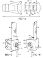
buckle tongue plate 10 performs the load limiting function. Thebuckle tongue plate 10 has a series of cut-outs 11 which leave cross beams 12 in a form of ladder structure. Thetongue plate 10 is inserted into abuckle head 14 so as to secure the safety belt around the vehicle occupant. Within the housing of thebuckle head 14 is a latch member (not shown) which engages into cut-out 11a on thetongue plate 10 and, under normal use, is retained in the cut-out 11a by virtue of thelateral bar 12a. Under conditions of extreme load,lateral bar 12a will break thus absorbing some of the energy.Lateral bar 12b will also break if the load applied to it is high enough, i.e. if enough energy has not already being absorbed bybar 12a breaking. However, thethird bar 13 is constructed to be stronger than thebars outs - Figures 5 and 6 illustrate another embodiment.
Seat belt webbing 8 is wound around aspool 15 which is mounted for rotation in aframe 16 on aspindle 17. Mounted on thespindle 17 on one side of theframe 16 is abobbin 18. Ametal strip 1 pass through astrip guide 19 and is fixed to the outer periphery of thebobbin 18. Under conditions of high load, thebelt webbing 8 is pulled in the direction of arrow A, causing thespool 15 to rotate in an anti-clockwise direction. This in turn rotates thespindle 17 and thus thebobbin 18 and themetal strip 1 is wound onto thebobbin 18 in an anti-clockwise direction. This absorbs some of the peak energy of a crash, i.e. it flattens out the crash pulse and reduces the possibility of injury to the occupant. - The
spool 15 may be part of a retractor or alternatively may be an independent spool mounted at another point in the seat belt system. It could be mounted via itsframe 16, to the buckle anchorage point or to the sill via mountinghole 20. - Figure 7 and 8 illustrate another embodiment of the invention wherein
seat belt webbing 8 is connected to ametal loop 21 which is integrally connected to anouter tube 22. Aninner tube 23 is connected viahole 25 inplate 24 to an anchorage point of the vehicle. The twotubes peg 26 is fixed to the outside tube and projects into the surface of the inside tube. At the end of theinside tube 23, a preformedstarter indentation 27 is made. - When a load is applied to the
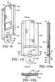
webbing 8 in the direction of arrow A, then theoutside tube 22 is pulled past theinside tube 23 and thepeg 26 deforms the surface of theinside tube 23, thus absorbing energy. - Figures 9 and 10 illustrate another embodiment which may be used at a shoulder mounting point or a sill end or indeed at a buckle end wherein it could be easily hidden under a seat. This could thus be used as a webbing buckle or retractor attachment. A
frame 30 is mounted to the appropriate anchorage point via mountinghole 31 in abracket 32 at one end of theframe 30.Seat belt webbing 8 is attached to a loop orring 33 which is held in the fork of asaddle 34. Thissaddle 34 sits in a slot in theframe 30 in normal use. At both ends of theframe 30 retaining stops or pins 35 are located to prevent thewebbing 8 being pulled completely out of the anchorage. Under high loads on thewebbing 8 theloop 33 exerts a high force on thesaddle 34 which slide in theslot 39 in theframe 30 and at the end of theslot 39 will deform the back plate of the frame. 30 In the cross-sectional views of Figures 10, 10a and 10b, like numerals are used for like parts. - Figures 11 and 12 illustrate a similar embodiment to Figures 9 and 10 except that instead of the slide attached to saddle 34 a
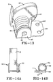
roller 36 is mounted on the lower arm of the loop orring 33 and is used to deform the back plate offrame 30. - Figure 13 illustrates another embodiment in which an
eccentric cam 40 rotates to bendmetal strip 1. Theeccentric cam 40 is mounted to rotate with aroller 41 mounted on aframe 42. Theframe 42 is mounted to an anchorage point of the belt or the buckle via mountingholes 43. Attached to and wound around theroller 41 is acable 44. Theother end 45 ofcable 44 is attached to seat belt webbing or to a buckle to take the load exerted on the belt. Under load thecable 44 unwinds from thebobbin 41, rotating the bobbin and thus the eccentric cam, and deflecting and deforming the metal plate 1 (which may be a spring leg of the frame 42). - Figure 14 illustrates another embodiment, in which rotation of a spool 50 (which may be the retractor spool or another bobbin with some webbing wound on it) causes a
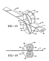
cutting wheel 51 to rotate, drivingteeth 52 intometal strip 1, so as to deform or cut themetal strip 1. Themetal strip 1 is mounted on acarriage 53 which moves in the direction of arrow A when thebelt webbing 8 is under load. Themetal strip 1 can be sheared or split to absorb energy. - Another embodiment is shown in Figures 15 and 16. In this embodiment the metal (which is preferably steel)
strip 1 is deformed by rotating teeth on a wheel which may be formed by the intermeshing elements of gear wheels. Twogear wheels 66 are mounted one on either face of themetal strip 1 on bearingpins 67 fixed to a mountingframe 68. The mounting frame is fixed to a fixed part of the vehicle via mounting holes 64 (Figure 16). - The
wheels 66 have radially extending arms somewhat in the form of gear teeth and these are arranged to intermesh with each other on either side of themetal strip 1 so as to deform the metal strip into the spaces between the gear teeth on first one and then the other of thegear wheels 66, as shown most clearly in Figure 16. The metal deforms as it passes between the gear teeth but straightens out as passes out again and is subject to the full load on the webbing or the buckle attachment at 65.Guide flanges 69 or provided on both sides of each of thegear wheels 66 and these meet as shown at 70 to synchronize the rotation of the gears. - In the embodiment of Figures 17 and 18 the
metal strip 1 is deformed by agear wheel 66 against a toothed mandrel (rather than against another rotating gear wheel). Like parts are referenced with like reference numbers and themandrel 71 hasupstanding teeth 72 against which the metal strip will pass. Again, themetal strip 1 is deformed as it passes thegear wheel 66 but straightens out again when subjected to the full force of the pull on the webbing or buckle mounting point at 65. The rack moves as the gear rotates. - In Figures 19 and 20 a further development of this concept is shown in which the gear teeth are arranged to punch out holes in the
metal strip 1. Again like parts are referenced accordingly. In this case one of the gear wheels has radially extending punchingteeth 73 while the other has radially indentedholes 74 to form a punching mandrel for the punching holes 73. Of course the female punch wheel could be replaced by a holed rack which would move along as load limiting progresses.
Claims (11)
- A safety restraint seat belt comprising:seat belt webbing for restraining a vehicle occupant in relation to a fixed part of the vehicle,an energy absorbing device arranged in the force path between the vehicle and said occupant, to absorb and/or dissipate energy above a predetermined level generated when the vehicle undergoes acceleration and/or deceleration, so as to reduce the effective force felt by said vehicle occupant, said energy absorbing device comprising:a metal strip having a deformable portion,means for deforming or bending said portion of the metal strip, said deforming means being arranged to transfer load from the seat belt to said metal strip.
- A safety restraint seat belt according to claim 1 wherein one end of the metal strip is attached to a mounting anchorage for the buckle fastening of the seat belt.
- A safety restraint seat belt according to claim 1 wherein one end of the metal strip is attached to a retractor mounting anchorage of the seat belt.
- A safety restraint seat belt according to any one of the preceding claims wherein the metal strip comprises a substantially planer member connected between a belt webbing anchorage and belt webbing and the deforming means comprises an arcuate slot through which the metal strip is drawn when subjected to force.
- A safety restraint seat belt according to any one of claims 1 to 3 wherein the metal strip comprises a non-planer piece of metal plate and the deforming means comprises a substantially planer guide slot so that the non-planer plate is bent into a substantially flat plate when it is drawn through the slot when subjected to force.
- A safety restraint seat belt according to any one of the preceding claims wherein the metal strip is formed of steel.
- A safety restraint seat belt according to any one of claims 1 to 3 wherein the deforming means comprises a roller and means for rolling the roller over the metal strip.
- A safety restraint seat belt according to any one of claims 1 to 3 comprising at least two coaxially mounted tubes arranged such that one is fixed to a mounting point of the seat belt and the other is subjected to forces on the seat belt and when one moves relative to the other under action of forces on the seat belt, one or the other is deformed.
- A safety restraint seat belt according to claim 8 wherein the deforming means comprises a peg attached to one of the tubes.
- A safety restraint seat belt according to claim 9 wherein the metal plate is formed with a cross section in the shape of a saddle and is attached to a height adjuster such that a load on the webbing above a predermined level, causes deformation of the metal plate.
- A safety restraint seat belt according to any one of the preceding claim comprising means for straightening out the metal strip after it has passed the deforming means.
Applications Claiming Priority (2)
| Application Number | Priority Date | Filing Date | Title |
|---|---|---|---|
| GB9721919A GB2330336A (en) | 1997-10-14 | 1997-10-14 | Energy absorbing device for a seat belt |
| GB9721919 | 1997-10-14 |
Publications (2)
| Publication Number | Publication Date |
|---|---|
| EP0909684A2 true EP0909684A2 (en) | 1999-04-21 |
| EP0909684A3 EP0909684A3 (en) | 2001-04-04 |
Family
ID=10820644
Family Applications (1)
| Application Number | Title | Priority Date | Filing Date |
|---|---|---|---|
| EP98308193A Withdrawn EP0909684A3 (en) | 1997-10-14 | 1998-10-08 | Energy absorbing belt anchors for safety belts in vehicles |
Country Status (3)
| Country | Link |
|---|---|
| US (2) | US5971489A (en) |
| EP (1) | EP0909684A3 (en) |
| GB (1) | GB2330336A (en) |
Cited By (13)
| Publication number | Priority date | Publication date | Assignee | Title |
|---|---|---|---|---|
| FR2790296A1 (en) * | 1999-02-26 | 2000-09-01 | Castellon Melchor Daumal | DEVICE FOR ABSORBING ENERGY IN A CONTINUOUS WAY WITH RELATIVE MOVEMENT, BY ROLLING A METAL BELT BETWEEN TWO PIECES OF DEFINED SECTION |
| EP1357312A1 (en) * | 2002-04-26 | 2003-10-29 | N.V. Bekaert S.A. | A force-limiting energy absorber |
| EP1419943A1 (en) * | 2002-11-13 | 2004-05-19 | Chris Cintos de Seguranca Ltda. | Energy absorbing device with torso displacement limiter |
| US7306260B1 (en) | 2006-10-19 | 2007-12-11 | Hyundai Motor Company | Lap fuse belt for a seat belt |
| WO2016089229A1 (en) | 2014-12-04 | 2016-06-09 | Eddy Current Limited Partnership | Energy absorbing apparatus |
| US10110089B2 (en) | 2014-08-18 | 2018-10-23 | Eddy Current Limited Partnership | Tuning of a kinematic relationship between members |
| US10498210B2 (en) | 2014-08-18 | 2019-12-03 | Eddy Current Limited Partnership | Tuning of a kinematic relationship between members |
| US10594200B2 (en) | 2014-08-18 | 2020-03-17 | Eddy Current Limited Partnership | Latching devices |
| US10693360B2 (en) | 2014-12-04 | 2020-06-23 | Eddy Current Limited Partnership | Transmissions incorporating eddy current braking |
| US10774887B2 (en) | 2014-12-04 | 2020-09-15 | Eddy Current Limited Partnership | Latch activation between members |
| US10953848B2 (en) | 2015-12-18 | 2021-03-23 | Eddy Current Limited Partnership | Variable behavior control mechanism for a motive system |
| US11050336B2 (en) | 2014-12-04 | 2021-06-29 | Eddy Current Limited Partnership | Methods of altering eddy current interactions |
| US11114930B2 (en) | 2014-12-04 | 2021-09-07 | Eddy Current Limited Partnership | Eddy current brake configurations |
Families Citing this family (33)
| Publication number | Priority date | Publication date | Assignee | Title |
|---|---|---|---|---|
| DE19911121A1 (en) * | 1998-03-13 | 1999-09-16 | Tokai Rubber Ind Ltd | Connecting arm for vehicle suspension |
| JP3468711B2 (en) * | 1999-02-18 | 2003-11-17 | 株式会社山田製作所 | Steering column shock absorber |
| US6659505B1 (en) | 2000-01-12 | 2003-12-09 | Autoliv Asp, Inc. | Adaptive variable load limited for primary occupant safety restraint |
| US6378939B1 (en) * | 2000-09-25 | 2002-04-30 | East/West Industries, Inc. | Variable energy attenuating apparatus |
| CN1161247C (en) * | 2001-04-29 | 2004-08-11 | 王武生 | Safety belt with energy-absorbing and controlling functions |
| US6619752B1 (en) | 2001-11-21 | 2003-09-16 | Cosco Management, Inc. | Extensible tether for juvenile vehicle seat |
| DE60213478T2 (en) * | 2002-03-22 | 2007-08-16 | Ashimori Industry Co. Ltd. | seatbelt |
| US7083237B2 (en) * | 2002-11-14 | 2006-08-01 | Cosco Management, Inc. | Shock absorber for juvenile vehicle seat tether |
| US20050012319A1 (en) * | 2003-07-14 | 2005-01-20 | Kurt Schulz | Load limiting structure for vehicle occupant restraint system |
| US6913288B2 (en) * | 2003-07-14 | 2005-07-05 | Key Safety Systems, Inc. | Load limiting structure for vehicle occupant restraint system |
| DE602004028440D1 (en) * | 2004-05-04 | 2010-09-16 | Ford Global Tech Llc | Seat belt restraint system |
| EP1904346A4 (en) * | 2005-07-08 | 2011-05-04 | Cosco Man Inc | Extensible restraint strap for an occupant-restraint system in a vehicle |
| US8104841B2 (en) * | 2006-12-08 | 2012-01-31 | Ford Global Technologies, Llc | Energy absorbing seat anchor restraint system for child safety seats |
| US20090173856A1 (en) * | 2008-01-08 | 2009-07-09 | Smart Technologies Inc. | Safety Device For A Cantilevered Beam And Boom Assembly Incorporating The Same |
| DE102008000972B4 (en) * | 2008-04-03 | 2017-06-22 | Robert Bosch Gmbh | Belt reel unit and method for rolling up at least one webbing and belt system for an occupant protection system in a vehicle with at least one such belt reel unit |
| US8091923B2 (en) * | 2008-06-27 | 2012-01-10 | GM Global Technology Operations LLC | Adaptive seat belt load limiter and method |
| US7784831B2 (en) | 2008-06-27 | 2010-08-31 | Gm Global Technology Operations, Inc. | Seat belt load limiting device |
| US8371425B2 (en) * | 2008-10-30 | 2013-02-12 | Ford Global Technologies, Llc | Dynamic displacement energy management device |
| US20110133439A1 (en) * | 2009-12-03 | 2011-06-09 | Jaguar Cars Limited | Restraint system load limiter |
| US8496293B2 (en) | 2010-12-13 | 2013-07-30 | Cosco Management, Inc. | Energy-dissipation system for juvenile vehicle seat |
| WO2013090382A1 (en) | 2011-12-13 | 2013-06-20 | Stryker Corporation | Energy absorbing fastening system |
| US9821178B2 (en) | 2013-02-08 | 2017-11-21 | D B Industries, Llc | Bracket assembly |
| US9090225B2 (en) * | 2013-08-02 | 2015-07-28 | Ford Global Technologies, Llc | Shoulder belt latch load-limiting system |
| CN204136815U (en) | 2013-09-13 | 2015-02-04 | 明门(中国)幼童用品有限公司 | Feet shock absorber and safety chair seats of car |
| US9168890B1 (en) * | 2014-09-03 | 2015-10-27 | Ford Global Technologies, Llc | Seat belt retractor with wedge clamp and load limiter |
| DE102015100149A1 (en) * | 2015-01-08 | 2016-07-14 | Raimund Huber | Electrical functional component with contact pin and method for producing an electrical functional component |
| US9827947B2 (en) | 2016-02-10 | 2017-11-28 | Ford Global Technologies, Llc | Load limiting seat belt buckle assemblies |
| US11584336B2 (en) * | 2020-10-30 | 2023-02-21 | Richard H. Galloway | Seat belt accessory and method of use |
| US11623607B1 (en) * | 2022-02-28 | 2023-04-11 | Nissan North America, Inc. | Vehicle seat assembly |
| US11724665B1 (en) | 2022-05-19 | 2023-08-15 | Ford Global Technologies, Llc | Load-limiting assembly for seatbelt |
| US11780404B1 (en) | 2022-05-23 | 2023-10-10 | Ford Global Technologies, Llc | Seatbelt assembly |
| CN115042739B (en) * | 2022-06-08 | 2023-07-11 | 上汽大众汽车有限公司 | Safety belt energy absorbing device, safety belt and vehicle |
| US11951932B1 (en) | 2022-09-28 | 2024-04-09 | Ford Global Technologies, Llc | Load-limiting assembly for seatbelt |
Citations (7)
| Publication number | Priority date | Publication date | Assignee | Title |
|---|---|---|---|---|
| US3026972A (en) * | 1959-04-13 | 1962-03-27 | Gen Dynamics Corp | Energy absorbing seat belt attachment |
| GB1399096A (en) * | 1971-07-16 | 1975-06-25 | Imp Metal Ind Kynoch Ltd | Vehicle safety belt systems |
| GB1419301A (en) * | 1972-01-12 | 1975-12-31 | Nissan Motor | Energy absorbing device |
| US4027905A (en) * | 1974-09-16 | 1977-06-07 | Nippon Soken, Inc. | Seat belt system for vehicle |
| US4358136A (en) * | 1979-11-30 | 1982-11-09 | Nippon Soken, Inc. | Energy absorbing device for use with vehicular seat belt |
| DE3842791A1 (en) * | 1988-12-20 | 1990-06-28 | Daimler Benz Ag | ENERGY ABSORBING DAMPING DEVICE FOR SAFETY BELTS OF MOTOR VEHICLES |
| US5211694A (en) * | 1989-06-20 | 1993-05-18 | Mazda Motor Corporation | Safety apparatus including an air bag and a safety belt supported on a vehicle with a deformable coupling |
Family Cites Families (10)
| Publication number | Priority date | Publication date | Assignee | Title |
|---|---|---|---|---|
| FR1603635A (en) * | 1967-12-15 | 1971-05-10 | ||
| US3680913A (en) * | 1968-09-06 | 1972-08-01 | Rolf Seybold | Attachment device for a retaining belt |
| DE2141668A1 (en) * | 1971-08-19 | 1973-03-22 | Emile Benoit | SEAT BELT ANCHORAGE |
| US3938627A (en) * | 1972-01-12 | 1976-02-17 | Nissan Motor Company Limited | Mechanical energy absorbing device and safety harness using the same |
| US4385775A (en) * | 1978-03-21 | 1983-05-31 | Nippon Soken, Inc. | Seat belt tensioning device for vehicle |
| EP0297537A3 (en) * | 1987-06-30 | 1989-05-10 | Nippon Seiko Kabushiki Kaisha | Webbing retractor |
| DE3723772A1 (en) * | 1987-07-17 | 1989-02-02 | Trw Repa Gmbh | POWER-LIMITING ENERGY ABSORBER FOR SAFETY BELT SYSTEMS |
| US4886296A (en) * | 1987-09-25 | 1989-12-12 | Volkswagen Ag | Belt force limiting device |
| JPH06239199A (en) * | 1993-02-17 | 1994-08-30 | Honda Motor Co Ltd | Anchor device for seat belt |
| DE69516490T2 (en) * | 1994-10-13 | 2000-11-09 | Takata Inc | Energy converter for seat belt retractors |
-
1997
- 1997-10-14 GB GB9721919A patent/GB2330336A/en not_active Withdrawn
-
1998
- 1998-10-01 US US09/165,258 patent/US5971489A/en not_active Expired - Fee Related
- 1998-10-08 EP EP98308193A patent/EP0909684A3/en not_active Withdrawn
-
1999
- 1999-09-01 US US09/388,367 patent/US6099078A/en not_active Expired - Fee Related
Patent Citations (7)
| Publication number | Priority date | Publication date | Assignee | Title |
|---|---|---|---|---|
| US3026972A (en) * | 1959-04-13 | 1962-03-27 | Gen Dynamics Corp | Energy absorbing seat belt attachment |
| GB1399096A (en) * | 1971-07-16 | 1975-06-25 | Imp Metal Ind Kynoch Ltd | Vehicle safety belt systems |
| GB1419301A (en) * | 1972-01-12 | 1975-12-31 | Nissan Motor | Energy absorbing device |
| US4027905A (en) * | 1974-09-16 | 1977-06-07 | Nippon Soken, Inc. | Seat belt system for vehicle |
| US4358136A (en) * | 1979-11-30 | 1982-11-09 | Nippon Soken, Inc. | Energy absorbing device for use with vehicular seat belt |
| DE3842791A1 (en) * | 1988-12-20 | 1990-06-28 | Daimler Benz Ag | ENERGY ABSORBING DAMPING DEVICE FOR SAFETY BELTS OF MOTOR VEHICLES |
| US5211694A (en) * | 1989-06-20 | 1993-05-18 | Mazda Motor Corporation | Safety apparatus including an air bag and a safety belt supported on a vehicle with a deformable coupling |
Cited By (33)
| Publication number | Priority date | Publication date | Assignee | Title |
|---|---|---|---|---|
| FR2790296A1 (en) * | 1999-02-26 | 2000-09-01 | Castellon Melchor Daumal | DEVICE FOR ABSORBING ENERGY IN A CONTINUOUS WAY WITH RELATIVE MOVEMENT, BY ROLLING A METAL BELT BETWEEN TWO PIECES OF DEFINED SECTION |
| US7048339B2 (en) | 2002-04-26 | 2006-05-23 | N.V. Bekaert S.A. | Force-limiting energy absorber |
| WO2003091596A1 (en) * | 2002-04-26 | 2003-11-06 | N.V. Bekaert S.A. | A force-limiting energy absorber |
| EP1357312A1 (en) * | 2002-04-26 | 2003-10-29 | N.V. Bekaert S.A. | A force-limiting energy absorber |
| EP1419943A1 (en) * | 2002-11-13 | 2004-05-19 | Chris Cintos de Seguranca Ltda. | Energy absorbing device with torso displacement limiter |
| US7128374B2 (en) | 2002-11-13 | 2006-10-31 | Chris Cintos De Seguranca Ltda. | Energy absorbing device with torso displacement limiter |
| US7306260B1 (en) | 2006-10-19 | 2007-12-11 | Hyundai Motor Company | Lap fuse belt for a seat belt |
| US11735992B2 (en) | 2014-08-18 | 2023-08-22 | Eddy Current Limited Partnership | Tuning of a kinematic relationship between members |
| US11632016B2 (en) | 2014-08-18 | 2023-04-18 | Eddy Current Limited Partnership | Tuning of a kinematic relationship between members |
| US10971988B2 (en) | 2014-08-18 | 2021-04-06 | Eddy Current Limited Partnership | Latching devices |
| US10110089B2 (en) | 2014-08-18 | 2018-10-23 | Eddy Current Limited Partnership | Tuning of a kinematic relationship between members |
| US10498210B2 (en) | 2014-08-18 | 2019-12-03 | Eddy Current Limited Partnership | Tuning of a kinematic relationship between members |
| US10594200B2 (en) | 2014-08-18 | 2020-03-17 | Eddy Current Limited Partnership | Latching devices |
| US11515776B2 (en) | 2014-08-18 | 2022-11-29 | Eddy Current Limited Partnership | Tuning of a kinematic relationship between members |
| US11437903B2 (en) | 2014-08-18 | 2022-09-06 | Eddy Current Limited Partnership | Latching devices |
| US10873242B2 (en) | 2014-08-18 | 2020-12-22 | Eddy Current Limited Partnership | Tuning of a kinematic relationship between members |
| US11316404B2 (en) | 2014-08-18 | 2022-04-26 | Eddy Current Limited Partnership | Tuning of a kinematic relationship between members |
| CN106999738A (en) * | 2014-12-04 | 2017-08-01 | 涡流有限合伙公司 | Energy absorbing device |
| US10774887B2 (en) | 2014-12-04 | 2020-09-15 | Eddy Current Limited Partnership | Latch activation between members |
| US11009089B2 (en) | 2014-12-04 | 2021-05-18 | Eddy Current Limited Partnership | Latch activation between members |
| CN112972922A (en) * | 2014-12-04 | 2021-06-18 | 涡流有限合伙公司 | Energy absorption device |
| US11050336B2 (en) | 2014-12-04 | 2021-06-29 | Eddy Current Limited Partnership | Methods of altering eddy current interactions |
| US11114930B2 (en) | 2014-12-04 | 2021-09-07 | Eddy Current Limited Partnership | Eddy current brake configurations |
| US10940339B2 (en) | 2014-12-04 | 2021-03-09 | Eddy Current Limited Partnership | Energy absorbing apparatus |
| US11777391B2 (en) | 2014-12-04 | 2023-10-03 | Eddy Current Limited Partnership | Methods of altering eddy current interactions |
| US11499596B2 (en) | 2014-12-04 | 2022-11-15 | Eddy Current Limited Partnership | Latch activation between members |
| US10693360B2 (en) | 2014-12-04 | 2020-06-23 | Eddy Current Limited Partnership | Transmissions incorporating eddy current braking |
| CN112972922B (en) * | 2014-12-04 | 2023-02-28 | 涡流有限合伙公司 | Energy absorption device |
| EP3226980A4 (en) * | 2014-12-04 | 2018-08-08 | Eddy Current Limited Partnership | Energy absorbing apparatus |
| CN106999738B (en) * | 2014-12-04 | 2023-06-23 | 涡流有限合伙公司 | Energy absorbing device |
| WO2016089229A1 (en) | 2014-12-04 | 2016-06-09 | Eddy Current Limited Partnership | Energy absorbing apparatus |
| US10953848B2 (en) | 2015-12-18 | 2021-03-23 | Eddy Current Limited Partnership | Variable behavior control mechanism for a motive system |
| US11878651B2 (en) | 2015-12-18 | 2024-01-23 | Eddy Current Limited Partnership | Variable behavior control mechanism for a motive system |
Also Published As
| Publication number | Publication date |
|---|---|
| EP0909684A3 (en) | 2001-04-04 |
| US6099078A (en) | 2000-08-08 |
| US5971489A (en) | 1999-10-26 |
| GB9721919D0 (en) | 1997-12-17 |
| GB2330336A (en) | 1999-04-21 |
Similar Documents
| Publication | Publication Date | Title |
|---|---|---|
| US6099078A (en) | Load limiting device for a seat belt | |
| US6773075B2 (en) | Four point seat belt restraint system | |
| US6722600B2 (en) | Seat belt retractor | |
| US20110133439A1 (en) | Restraint system load limiter | |
| JP7213843B2 (en) | retractor pretensioner assembly | |
| KR20190026565A (en) | Three-point seatbelt device | |
| US5788280A (en) | Seat belt system | |
| EP1079996A1 (en) | Retractor for vehicles | |
| US7635150B2 (en) | Automotive pretensioner seatbelt system | |
| EP3733447B1 (en) | Child safety seat with a triggerable harness belt tensioning mechanism | |
| JP2004276742A (en) | Seat belt retractor and its retracting method | |
| CA2574891C (en) | Seat belt pretensioner | |
| US20020038834A1 (en) | Seatbelt retractor | |
| EP1498327B1 (en) | Pretensioner | |
| CN101274617A (en) | Seat belt retractor and seat belt apparatus having the same | |
| US20050012319A1 (en) | Load limiting structure for vehicle occupant restraint system | |
| GB1601104A (en) | Safety restraint apparatus | |
| JP3464209B2 (en) | Seat belt retractor | |
| RU2319625C2 (en) | Energy-absorbing device with limited displacement of passenger body | |
| CN101274616B (en) | Seat belt retractor and seat belt apparatus having the same | |
| EP0928722A3 (en) | Seat belt retractor | |
| JPH01285438A (en) | Preloader device for seat belt | |
| EP3323671A1 (en) | Method of reducing the values of deccelerations acting on motor vehicle occupant's body during an accident and safety automotive seat where this method is used | |
| JP2019098840A (en) | Seat belt device | |
| EP2108551B1 (en) | Belt system |
Legal Events
| Date | Code | Title | Description |
|---|---|---|---|
| PUAI | Public reference made under article 153(3) epc to a published international application that has entered the european phase |
Free format text: ORIGINAL CODE: 0009012 |
|
| AK | Designated contracting states |
Kind code of ref document: A2 Designated state(s): AT BE CH CY DE DK ES FI FR GB GR IE IT LI LU MC NL PT SE |
|
| AX | Request for extension of the european patent |
Free format text: AL;LT;LV;MK;RO;SI |
|
| PUAL | Search report despatched |
Free format text: ORIGINAL CODE: 0009013 |
|
| AK | Designated contracting states |
Kind code of ref document: A3 Designated state(s): AT BE CH CY DE DK ES FI FR GB GR IE IT LI LU MC NL PT SE |
|
| AX | Request for extension of the european patent |
Free format text: AL;LT;LV;MK;RO;SI |
|
| STAA | Information on the status of an ep patent application or granted ep patent |
Free format text: STATUS: THE APPLICATION IS DEEMED TO BE WITHDRAWN |
|
| 18D | Application deemed to be withdrawn |
Effective date: 20010503 |