The present invention relates to a safety restraint for
use in a vehicle and particularly to a seat belt.
Modern seat belts comprise a length of webbing arranged
to pass diagonally across the torso of a vehicle occupant
and generally horizontally across the hip region of the
vehicle occupant (so-called lap portion of the belt). This
is known as a three point belt system. One end of the belt
webbing is firmly attached to a structural part of the
vehicle such as the floor, and the other end is attached to
the spool of a retractor which itself is firmly attached to
a structural part of the vehicle, usually the side, B-pillar.
The retractor automatically keeps any slack in the
belt wound onto the spool and thus keeps a tension in the
belt. Between the retractor and the other fixed point, a
fastening element such as a metal tongue is fixed to the
belt with which it can be fastened into a buckle which
itself is attached to fixed part of the vehicle on the other
side of the occupant seat.
A clock spring in the retractor allows pay out of
webbing under the influence of relatively gentle forwardly
directed inertia of the vehicle occupant, for example to
allow for normal movement of the occupant such as reaching
forward to activate in car controls, glove compartments or
door pockets.
In the event of a crash the sudden high forward
momentum of the occupant activates a crash sensor which
locks the spool against rotation and prevents forward motion
of the occupant to prevent him colliding with the internal
fixtures of the vehicle such as the steering wheel,
dashboard or windscreen.
However it has been found in high velocity crashes that
the sudden locking of the seat belt can itself cause injury
to the occupant due to the sudden impact of the torso with
the belt webbing.
In recent years it has been proposed to introduce a
load limiting effect into the seat belt system so as to
allow a limited and controlled forward motion of the
occupant after the retractor has locked. This decreases the
forces exerted by the belt on the occupant's torso.
Load limiting proposals are described in EP 0 297 537
wherein a plastically deformable member is used in the
retractor, and particularly between the spool and inner most
winding of the belt webbing. Alternative load limiting
proposals are known in which crushable bushings or nuts or
deformable torsion bars are placed in the retractor in the
force path between the spool locking mechanism and belt
webbing. These proposals are complex and expensive and
require the retractor to be specially designed and
constructed to incorporate them.
Another proposal is described in EP 715 997 in which a
slotted metal plate is fixed to a seat belt anchorage point
and the retractor is fixed to the plate so that, under load,
it slides on the plate deforming the metal and dissipating
energy. However, this requires expensive modifications to
the retractor.
The present invention proposes improved, simpler and
more cost effective load limiting arrangements for seat
belts.
According to the present invention there is provided a
safety restraint seat belt comprising:
Preferably one end of the metal strip is attached to a
mounting anchorage for the buckle fastening of the seat
belt. Alternatively one end of the metal strip may be
attached to a retractor mounting anchorage of the seat belt.
Holes could be made to attach webbing.
According to one embodiment the metal strip is a
substantially planer member connected between a belt webbing
anchorage and belt webbing and the deforming means comprises
an arcuate slot through which the metal strip is drawn, i.e.
pulled or pushed to deform it into a curved shape when
subjected to extreme forces. Alternatively a bent piece of
metal plate may be pulled through a substantially planer
guide block so that the bent plate is bent into a
substantially flat plate.
According to a second embodiment the metal strip
comprises cut-outs so as to form generally a ladder shape
with rungs, and the deforming means comprises a member
engaging in the cut-outs of the metal strip to break or cut
the rungs as it moves along the ladder under load. This
embodiment may be incorporated into the buckle mechanism
such that the tongue is formed in such a ladder shape and
the buckle latch forms the deforming means.
According to a third embodiment the metal strip may be
deformed by a cam rotated by action of the protraction of
the seat belt under extreme forces. The cam may be mounted
to rotate with the retractor web-winding spool, for example
attached to the spindle or shaft of the retractor spool.
Alternatively it may be attached at any point in the belt
webbing force path such as to a winding axis of a member
around which a length of webbing is wound.
In a fourth embodiment the metal strip has one end
attached to the spindle of a winding spool or bobbin, (which
may be the retractor bobbin or may be another bobbin
attached in the force path of the seat belt to rotate as the
belt is withdrawn). As webbing is extracted under force the
rotation of the bobbin causes the metal strip, preferably
formed of steel, to be wound around the spindle of the
bobbin.
According to another embodiment the metal strip may be
deformed by action of a roller pulled over the metal strip,
or alternatively by means of a slider.
In a variation of this embodiment two coaxially mounted
tubes are arranged such that one is fixed to a mounting
point of the seat belt and the other is subjected to forces
on the seat belt and when one moves relative to the other
under action of forces on the seat belt, one or the other is
deformed, for example by means of a peg attached to one of
the tubes and preferably a preformed starter indentation in
the other.
The metal plate may be in a saddle shape, for example
attached to a height adjuster such that an excessive load on
the webbing causes the saddle to deform or causes the saddle
to deform another part, for example the back of the frame of
the height adjuster. This could also be done using a roller
on the loop attached to the webbing in a height adjuster.
Under normal conditions this roller would fit and slide
easily in a groove or cut-out in the back plate but under
excessive load it will ride past the length of the groove
and deform part of the back plate.
Alternatively the deforming means may comprise rotating
members with fins which deform a metal plate as it is pulled
passed the fins. Rotating wheels comprising fins could be
mounted on both faces of the metal plate, or on one face
with, for example, a toothed rack against the other face to
form a mandrel for bending the metal. Preferably the metal
strip straightens out again after it has passed the
deforming means in this embodiment.
The fins could instead comprise hole punching members.
Again a mandrel, either in the form of a rotating wheel with
holes corresponding in size and position to the punching
member, or in the form of a rack with corresponding holes,
will be provided.
The metal strip may therefore be bent, straightened,
otherwise deformed, sheared, or split or punched to absorb
energy.
For a better understanding of the present invention,
and to show how the same may be carried into effect,
reference will now be made to the accompanying drawings, in
which:
Figure 1 is a perspective view of a first embodiment of
the invention.
Figures 2 and 3 illustrate a second embodiment of the
invention, in perspective view in Figure 2 and in side view
in Figure 3.
Figure 4 is a top plan view of another embodiment of
the invention.
Figures 5 and 6 are right side and left side
perspective views respectively of yet another embodiment of
the invention.
Figures 7 and 8 illustrate in perspective and in cross-sectional
view respectively a further embodiment of the
invention.
Figure 9 is a perspective view of another embodiment of
the invention.
Figure 10 is a front plan view of the embodiment of
Figure 9.
Figures 10a and 10b show respective cross-sections of
the view of Figure 10.
Figure 11 is a perspective view of another embodiment
of the invention.
Figure 12 is a front plan view of the embodiment of
Figure 11.
Figures 12a and 12b are respective cross-sections of
the view of Figure 12.
Figure 13 is a perspective view of yet another
embodiment of the invention.
Figure 14 illustrates in rear and side view, another
embodiment of the invention.
Figures 15 and 16 illustrate in perspective and in side
view respectively another embodiment of the invention.
Figures 17 and 18 illustrate in perspective and in side
view respectively another embodiment of the invention.
Figures 19 and 20 illustrate in perspective and in side
view respectively another embodiment of the invention.
Figure 1 illustrates the first embodiment of the
invention in which a generally planer metal strip 1 which is
is pulled through a frame 2 which has a curved slot 3 to
absorb energy of the safety belt system under high loads.
One of the strip 1 and frame 2 is attached to a fixed
anchorage position on the vehicle. This may be at the
buckle end or at the retractor end or at the sill mounting
end of a standard three point seat belt. The other is
attached to belt webbing or to a buckle or retractor
mounting. As the strip 1 is pulled through the curved frame
slot 2, the metal strip 1 deforms into the curved shape
indicated at 5.
This embodiment is particularly easy and cheap to
integrate into a vehicle. The flat metal strip 1 can easily
be hidden under a seat or in other discrete places in the
vehicle. Any combination of shapes is possible. It is not
necessary to have a flat metal strip deformed into a curved
shape: the opposite would work just as well.
For example, in the embodiment of Figures 2 and 3 a
bent metal strip 1, attached to a fixed anchorage point of
the vehicle via block 6, is pulled through straightening
guide blocks 7 in the direction of arrows A. The guide
blocks 7 flatten out the curves in metal strip 1 thus
absorbing some of the energy of the system. The upper end
of metal plate 1 is attached to seat belt webbing 8.
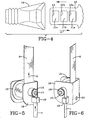
In the embodiment of Figure 4 a buckle tongue plate 10
performs the load limiting function. The buckle tongue
plate 10 has a series of cut-outs 11 which leave cross beams
12 in a form of ladder structure. The tongue plate 10 is
inserted into a buckle head 14 so as to secure the safety
belt around the vehicle occupant. Within the housing of the
buckle head 14 is a latch member (not shown) which engages
into cut-out 11a on the tongue plate 10 and, under normal
use, is retained in the cut-out 11a by virtue of the lateral
bar 12a. Under conditions of extreme load, lateral bar 12a
will break thus absorbing some of the energy. Lateral bar
12b will also break if the load applied to it is high
enough, i.e. if enough energy has not already being absorbed
by bar 12a breaking. However, the third bar 13 is
constructed to be stronger than the bars 12a and 12b. It
may be made of a different, stronger material or may be made
of different dimensions to make it stronger. It is of
course imperative that the last bar does not break, even
under conditions of extremely high load so that the vehicle
occupant is safely restrained. Preferably some form of
plastic coating or similar arrangement is put over the cut- outs
11b and 11c to ensure that the buckle does not falsely
engage in these cut outs in normal use since this would
limit the load limiting effect.
Figures 5 and 6 illustrate another embodiment. Seat
belt webbing 8 is wound around a spool 15 which is mounted
for rotation in a frame 16 on a spindle 17. Mounted on the
spindle 17 on one side of the frame 16 is a bobbin 18. A
metal strip 1 pass through a strip guide 19 and is fixed to
the outer periphery of the bobbin 18. Under conditions of
high load, the belt webbing 8 is pulled in the direction of
arrow A, causing the spool 15 to rotate in an anti-clockwise
direction. This in turn rotates the spindle 17 and thus the
bobbin 18 and the metal strip 1 is wound onto the bobbin 18
in an anti-clockwise direction. This absorbs some of the
peak energy of a crash, i.e. it flattens out the crash pulse
and reduces the possibility of injury to the occupant.
The spool 15 may be part of a retractor or
alternatively may be an independent spool mounted at another
point in the seat belt system. It could be mounted via its
frame 16, to the buckle anchorage point or to the sill via
mounting hole 20.
Figure 7 and 8 illustrate another embodiment of the
invention wherein seat belt webbing 8 is connected to a
metal loop 21 which is integrally connected to an outer tube
22. An inner tube 23 is connected via hole 25 in plate 24
to an anchorage point of the vehicle. The two tubes 22 and
23 are a tight fit but can slide relative to each other. A
peg 26 is fixed to the outside tube and projects into the
surface of the inside tube. At the end of the inside tube
23, a preformed starter indentation 27 is made.
When a load is applied to the webbing 8 in the
direction of arrow A, then the outside tube 22 is pulled
past the inside tube 23 and the peg 26 deforms the surface
of the inside tube 23, thus absorbing energy.
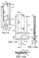
Figures 9 and 10 illustrate another embodiment which
may be used at a shoulder mounting point or a sill end or
indeed at a buckle end wherein it could be easily hidden
under a seat. This could thus be used as a webbing buckle
or retractor attachment. A frame 30 is mounted to the
appropriate anchorage point via mounting hole 31 in a
bracket 32 at one end of the frame 30. Seat belt webbing 8
is attached to a loop or ring 33 which is held in the fork
of a saddle 34. This saddle 34 sits in a slot in the frame
30 in normal use. At both ends of the frame 30 retaining
stops or pins 35 are located to prevent the webbing 8 being
pulled completely out of the anchorage. Under high loads on
the webbing 8 the loop 33 exerts a high force on the saddle
34 which slide in the slot 39 in the frame 30 and at the end
of the slot 39 will deform the back plate of the frame. 30
In the cross-sectional views of Figures 10, 10a and 10b,
like numerals are used for like parts.
Figures 11 and 12 illustrate a similar embodiment to
Figures 9 and 10 except that instead of the slide attached
to saddle 34 a roller 36 is mounted on the lower arm of the
loop or ring 33 and is used to deform the back plate of
frame 30.
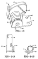
Figure 13 illustrates another embodiment in which an
eccentric cam 40 rotates to bend metal strip 1. The
eccentric cam 40 is mounted to rotate with a roller 41
mounted on a frame 42. The frame 42 is mounted to an
anchorage point of the belt or the buckle via mounting holes
43. Attached to and wound around the roller 41 is a cable
44. The other end 45 of cable 44 is attached to seat belt
webbing or to a buckle to take the load exerted on the belt.
Under load the cable 44 unwinds from the bobbin 41, rotating
the bobbin and thus the eccentric cam, and deflecting and
deforming the metal plate 1 (which may be a spring leg of
the frame 42).
Figure 14 illustrates another embodiment, in which
rotation of a spool 50 (which may be the retractor spool or
another bobbin with some webbing wound on it) causes a
cutting wheel 51 to rotate, driving teeth 52 into metal
strip 1, so as to deform or cut the metal strip 1. The
metal strip 1 is mounted on a carriage 53 which moves in the
direction of arrow A when the belt webbing 8 is under load.
The metal strip 1 can be sheared or split to absorb energy.
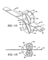
Another embodiment is shown in Figures 15 and 16. In
this embodiment the metal (which is preferably steel) strip
1 is deformed by rotating teeth on a wheel which may be
formed by the intermeshing elements of gear wheels. Two
gear wheels 66 are mounted one on either face of the metal
strip 1 on bearing pins 67 fixed to a mounting frame 68.
The mounting frame is fixed to a fixed part of the vehicle
via mounting holes 64 (Figure 16).
The wheels 66 have radially extending arms somewhat in
the form of gear teeth and these are arranged to intermesh
with each other on either side of the metal strip 1 so as to
deform the metal strip into the spaces between the gear
teeth on first one and then the other of the gear wheels 66,
as shown most clearly in Figure 16. The metal deforms as it
passes between the gear teeth but straightens out as passes
out again and is subject to the full load on the webbing or
the buckle attachment at 65. Guide flanges 69 or provided
on both sides of each of the gear wheels 66 and these meet
as shown at 70 to synchronize the rotation of the gears.
In the embodiment of Figures 17 and 18 the metal strip
1 is deformed by a gear wheel 66 against a toothed mandrel
(rather than against another rotating gear wheel). Like
parts are referenced with like reference numbers and the
mandrel 71 has upstanding teeth 72 against which the metal
strip will pass. Again, the metal strip 1 is deformed as
it passes the gear wheel 66 but straightens out again when
subjected to the full force of the pull on the webbing or
buckle mounting point at 65. The rack moves as the gear
rotates.
In Figures 19 and 20 a further development of this
concept is shown in which the gear teeth are arranged to
punch out holes in the metal strip 1. Again like parts are
referenced accordingly. In this case one of the gear wheels
has radially extending punching teeth 73 while the other has
radially indented holes 74 to form a punching mandrel for
the punching holes 73. Of course the female punch wheel
could be replaced by a holed rack which would move along as
load limiting progresses.