EP0909578B1 - Process and apparatus for conditioning a gas to be combusted and an exhaust gas - Google Patents
Process and apparatus for conditioning a gas to be combusted and an exhaust gas Download PDFInfo
- Publication number
- EP0909578B1 EP0909578B1 EP98119082A EP98119082A EP0909578B1 EP 0909578 B1 EP0909578 B1 EP 0909578B1 EP 98119082 A EP98119082 A EP 98119082A EP 98119082 A EP98119082 A EP 98119082A EP 0909578 B1 EP0909578 B1 EP 0909578B1
- Authority
- EP
- European Patent Office
- Prior art keywords
- liquid
- chambers
- exhaust gas
- conditioning
- combustion gas
- Prior art date
- Legal status (The legal status is an assumption and is not a legal conclusion. Google has not performed a legal analysis and makes no representation as to the accuracy of the status listed.)
- Expired - Lifetime
Links
Images

Classifications
-
- F—MECHANICAL ENGINEERING; LIGHTING; HEATING; WEAPONS; BLASTING
- F23—COMBUSTION APPARATUS; COMBUSTION PROCESSES
- F23J—REMOVAL OR TREATMENT OF COMBUSTION PRODUCTS OR COMBUSTION RESIDUES; FLUES
- F23J15/00—Arrangements of devices for treating smoke or fumes
- F23J15/02—Arrangements of devices for treating smoke or fumes of purifiers, e.g. for removing noxious material
- F23J15/04—Arrangements of devices for treating smoke or fumes of purifiers, e.g. for removing noxious material using washing fluids
-
- B—PERFORMING OPERATIONS; TRANSPORTING
- B01—PHYSICAL OR CHEMICAL PROCESSES OR APPARATUS IN GENERAL
- B01D—SEPARATION
- B01D53/00—Separation of gases or vapours; Recovering vapours of volatile solvents from gases; Chemical or biological purification of waste gases, e.g. engine exhaust gases, smoke, fumes, flue gases, aerosols
- B01D53/34—Chemical or biological purification of waste gases
- B01D53/74—General processes for purification of waste gases; Apparatus or devices specially adapted therefor
- B01D53/77—Liquid phase processes
Definitions
- the invention relates to a method for conditioning a Combustion gas, especially combustion air, and an exhaust gas, each of a heater or Internal combustion engine are supplied to or discharged from this, wherein the combustion gas through a first space and the exhaust gas by communicating with the first room connected second room above the connection passed through both rooms and with one below liquid in the rooms are sprayed Liquid level at a level higher than the compound is held, and a device for conditioning a combustion gas, in particular combustion air, and an exhaust gas, each of a heater or Internal combustion engine are supplied to or discharged from this, with two communicating with each other via a connection connected rooms, the combustion gas through the one (first) room and the exhaust gas through the other (second) Room passed above the connection and by means of a spray device with a down liquid in the rooms is sprayed, whose fluid level is at a level higher than the compound is held.
- the following is general treatment under conditioning understood a combustion gas or an exhaust gas, the combustion and exhaust gas conditions of a heating device, in particular a boiler or an internal combustion engine, especially a diesel engine improve.
- Such a conditioning method and such Conditioning devices are e.g. through FR-A-26 36 129 known.
- Water vapor is contained in the exhaust gas from a combustion process, which is particularly common in the combustion of hydrocarbons forms from which essentially fuels like natural gas and mineral oil. When burned One liter of heating oil creates steam, for example an equivalent of one liter of liquid water. This Water usually goes unused as a component in the vapor form of the exhaust gas into the atmosphere. With the so-called The exhaust gas from the combustion process is used for condensing purposes cooled down so far that the contained water vapor liquefies and the heat of vaporization released can be used is made.
- From FR-A-26 36 129 is a device for moistening known from fresh air, with the dry air from bottom to bottom flows through a first wash tower at the top before entering one Combustion chamber arrives.
- the hot and humid exhaust gases from the combustion chamber flow through a second wash tower before entering the Get free. That is at the bottom of the second wash tower Collecting condensate is led to the upper end of the first wash tower and pumped in there.
- the condensate of the first wash tower is accordingly in the second Wash tower injected.
- the floors of the wash towers are through one Line connected to compensate for the condensate level.
- the present invention is therefore based on the object a method and an apparatus of the aforementioned Kind in further training that an improved Heat balance between exhaust gas and combustion gas reached can be.
- combustion gas and the exhaust gas can be several different Go through treatment stages.
- the combustion gas leaves the first room warmed, humidified and cleaned.
- the exhaust gas leaves the second room cooled, dehumidified and cleaned.
- the liquid in the room especially close of their liquid level.
- the one with particles Enriched liquid can, for example, in a sewage system can be initiated, or it can be used for water emulsion e.g. of the fuel oil for a diesel engine be used.
- the procedure provided that the in the rooms liquid is kept in constant motion.
- the exhaust gas is sprayed to an acidic liquid that does not enter the sewer system may be derived. Therefore, the Liquid, at least before it is drained off Neutralizer neutralized.
- the liquid can be cooled externally, whereby under "external" not the (internal) cooling of the liquid through the combustion gas, but the cooling through additional facilities such as Heat exchanger understood becomes.
- controlled external cooling of the liquid can be the temperature of the combustion gas, at least within certain limits.
- the above object is achieved in a device initially mentioned type solved according to the invention in that the two rooms have a common floor and that one or both rooms in several, approximately vertically running Subspaces are divided, which are from the combustion gas or Exhaust gas in succession, in particular in a serpentine shape, be flowed through.
- Combustion gas and exhaust gas can initially flow in counterflow and then sprayed with the liquid in cocurrent and then e.g. in the last part of a droplet separation be subjected before they flow out of the respective room.
- the conditioning device according to the invention can by two preferably vertical hollow profiles (e.g. pipes with rectangular or round cross section), which are formed in are connected to each other in such a way that with partial filling with the liquid the liquid columns in both Communicate hollow profiles with each other.
- the sprayers supplied liquid is preferred in the rooms taken near the ground.
- the common ground is part the connection between the two rooms. Both rooms therefore have a common liquid "swamp" that the Spray devices preferably removed liquid supplied becomes.
- the inlet for the exhaust gas is preferred in this room arranged below the outlet.
- the spray device can be anywhere in the room are located, but it is preferably above the respective higher inlet or outlet for the combustion gas or arranged for the exhaust gas, so that liquid is sprayed down into the respective room.
- an overflow line which is between the Connection and the deepest one or Outlet for the combustion gas or for the exhaust gas is located.
- This overflow line can also be used for automatic limitation serve the maximum liquid level in the rooms.
- the respective spraying device is connected to a circuit line those in the rooms, preferably down in the liquid sump, liquid is supplied.
- At least the liquid in the rooms in Movement-holding movement device is provided, with which one Deposition of particles within the conditioning device and especially counteracted within the rooms becomes.
- Circulation line can be provided, through which the or liquid removed from the rooms, preferably in a circuit, is returned to the rooms.
- the e.g. with a Circulation pump equipped circulation pipe keeps the in the Clear and fluid flowing in the pipes in motion and prevents particles from settling.
- a heat exchanger is provided through which the liquid is conductive for cooling.
- the space requirement of the conditioning device according to the invention can be reduced if the two rooms through a common partition are separated.
- the several subspaces can be checkered be arranged side by side, whereby it is preferred common partitions with corresponding connection openings to have. But also a linear arrangement of the subspaces one after the other and / or a connection of the individual Partial rooms via lines are possible.
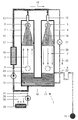
- the conditioning device designated 1 in FIG. 1 serves to condition both a combustion gas 2, e.g. Combustion air or fuel gas, as well as an exhaust gas 3 a heater or internal combustion engine (Not shown).
- a combustion gas 2 e.g. Combustion air or fuel gas
- an exhaust gas 3 e.g. Combustion air or fuel gas
- the conditioning device 1 has two rooms 4, 7 in Form of vertical hollow profiles (tubes) with round or polygonal cross section.
- first room 4 that is Combustion gas 2 in and through an upper inlet 5 diverted a lower outlet 6 located lower.
- the exhaust gas 3 is via a lower one Inlet 8 in and over a higher upper outlet 9th re-routed.
- the flow directions of combustion gas 2 and exhaust gas 3 in the two rooms 4, 7 are through Flow arrows indicated.
- the two rooms 4, 7 are over a connection 10 communicating with each other, wherein they are completed down by a common floor 11 are.
- each room 4, 7 is above the higher one Inlet 5 or outlet 9, a spray device 12 or 13 provided over which a liquid 14, 15 over a large area is sprayed down or injected.
- This sprayed Liquid 14, 15 collects below in a liquid "sump" 16.
- the one in rooms 4, 7 Liquid is condensate from the combustion process, which is constantly caused by water from the combustion the hydrocarbons are enriched and renewed.
- the combustion gas 2 is in cocurrent and the exhaust gas 3 in counterflow with respect to the spray direction the liquid 14, 15 passed through the rooms 4, 7.
- the liquid sump 16 is connected via a circuit line 17 liquid is removed in the direction of arrow 19 by means of a pump 18 and the spray devices 12, 13 fed so that there is a closed liquid cycle.
- the sensible heat contained in the exhaust gas 3 goes to the sprayed colder liquid 15 over.
- the exhaust gas 3 is cooled and warmed the sprayed liquid 15.
- the in Exhaust gas 3 contains latent heat, i.e. the heat of vaporization of the water vapor carried in the exhaust gas 3 goes to the sprayed Liquid 15 over.
- the exhaust gas 3 can do more Give off heat, the sprayed liquid 15 more warm take up.
- the water vapor contained in the exhaust gas 3 liquefies yourself.
- the exhaust gas 3 is dehumidified and the sprayed Liquid 15 enriched with water. Contained in the exhaust gas 3 Particles are caused by the sprayed-in liquid 15 washed out. Overall, the exhaust gas 3 leaves the second Room 7 cooled, dehumidified and cleaned.
- Rooms 4, 7 are connected to one above connection 10 provided overflow line 23 equipped via the maximum liquid level 24 or the filling of the rooms 4, 7 limited and excess liquid in a sewer 25 is dissipated. So that no too acidic liquid is discharged, there is a neutralization device in the circuit line 17 26 provided in which the liquid is neutralized accordingly.
- the one enriched with particles Liquid can also be used to emulsify the water Fuel oil for e.g. a diesel engine can be used.
- the liquid delivered in the circuit line 17 is additionally via a line 27 and by means of a pump 28 conductive via a heat exchanger 29 with which the liquid Deprived of heat and e.g. are released to the outside air 30 can.
- FIGs. 2 and 3 is an embodiment of an egg according to the invention Conditioning device 101 shown, both of which communicatively interconnected via connection 110 Rooms 104, 107 from each other by a common partition 131 are separated.
- the two rooms 104, 107 are still through two partitions 132, 133 and a continuous one Intermediate wall 134 like a chessboard in four vertical Subspaces 104a-104d and 107a-107d divided.
- the flow of combustion gas described below 102 and exhaust 103 through the conditioning device 101 is in the fig. 2 and 3 illustrated by flow arrows.
- the combustion gas 102 flows through a lower inlet 105 into the first sub-space 104a, flows upwards in it, until it has an upper connection opening in the partition 132 reaches the second subspace 104b. In this it flows down and passes through a lower connection opening in the intermediate wall 134 into the third sub-space 104c one it flows through up until it finally over an upper connection opening in the intermediate wall 132 in FIGS flows into fourth sub-space 104d. Via the lower outlet 106 occurs the combustion gas flowing down in the fourth sub-space 104d 102 out.
- the exhaust gas 103 flows into the through a lower inlet 108 a first subspace 107a, flows upward in this until it via an upper connection opening in the intermediate wall 133 enters the second subspace 107b. It flows in this down and enters through a lower connection opening the partition 134 into the third subspace 107c, the it flows upwards until it finally reaches an upper one Connection opening in the partition 133 in the fourth Partial space 107d flows. Steps over the lower outlet 109 the exhaust gas 103 which has flowed downward in the fourth subspace 107d out.
- the vertical subspaces 104a-104d and 107a-107d respectively thus successively from the combustion gas 102 or from the exhaust gas 103 and flows in a serpentine shape.
- the combustion gas 102 and exhaust 103 may e.g. in the second and third subspaces 104b, 104c and 107b, 107c in direct current and then sprayed with liquid in countercurrent from above and finally e.g. in the last compartment 104d or 107d are subjected to droplet separation before them via the outlet 106 or 109 from the conditioning device 101 exit.
Abstract
Description
Die Erfindung betrifft ein Verfahren zur Konditionierung eines Verbrennungsgases, insbesondere von Verbrennungsluft, und eines Abgases, die jeweils einer Heizeinrichtung oder Verbrennungskraftmaschine zu- bzw. von dieser abgeführt werden, wobei das Verbrennungsgas durch einen ersten Raum und das Abgas durch einen mit dem ersten Raum kommunizierend verbundenen zweiten Raum jeweils oberhalb der Verbindung beider Räume hindurchgeleitet und dabei mit einer sich unten in den Räumen befindenden Flüssigkeit besprüht werden, deren Flüssigkeitsniveau auf einem Niveau höher als die Verbindung gehalten wird, sowie eine Vorrichtung zur Konditionierung eines Verbrennungsgases, insbesondere von Verbrennungsluft, und eines Abgases, die jeweils einer Heizeinrichtung oder Verbrennungskraftmaschine zu- bzw. von dieser abgeführt werden, mit zwei über eine Verbindung miteinander kommunizierend verbundenen Räumen, wobei das Verbrennungsgas durch den einen (ersten) Raum und das Abgas durch den anderen (zweiten) Raum jeweils oberhalb der Verbindung hindurchgeleitet und dabei mittels einer Sprüheinrichtung mit einer sich unten in den Räumen befindenden Flüssigkeit besprüht werden, deren Flüssigkeitsniveau auf einem Niveau höher als die Verbindung gehalten wird.The invention relates to a method for conditioning a Combustion gas, especially combustion air, and an exhaust gas, each of a heater or Internal combustion engine are supplied to or discharged from this, wherein the combustion gas through a first space and the exhaust gas by communicating with the first room connected second room above the connection passed through both rooms and with one below liquid in the rooms are sprayed Liquid level at a level higher than the compound is held, and a device for conditioning a combustion gas, in particular combustion air, and an exhaust gas, each of a heater or Internal combustion engine are supplied to or discharged from this, with two communicating with each other via a connection connected rooms, the combustion gas through the one (first) room and the exhaust gas through the other (second) Room passed above the connection and by means of a spray device with a down liquid in the rooms is sprayed, whose fluid level is at a level higher than the compound is held.
Im folgenden wird unter Konditionierung allgemein das Behandeln eines Verbrennungsgases oder eines Abgases verstanden, um die Verbrennungs- und Abgasverhältnisse einer Heizeinrichtung, insbesondere eines Heizkessels, oder einer Verbrennungskraftmaschine, insbesondere eines Dieselmotors, zu verbessern.The following is general treatment under conditioning understood a combustion gas or an exhaust gas, the combustion and exhaust gas conditions of a heating device, in particular a boiler or an internal combustion engine, especially a diesel engine improve.
Ein derartiges Konditionierungsverfahren und eine derartige Konditionierungsvorrichtung sind z.B. durch die FR-A-26 36 129 bekanntgeworden.Such a conditioning method and such Conditioning devices are e.g. through FR-A-26 36 129 known.
Im Abgas aus einem Verbrennungsprozeß ist Wasserdampf enthalten, der sich insbesondere bei der Verbrennung von Kohlenwasserstoffen bildet, aus welchen im wesentlichen Brennstoffe wie Erdgas und Mineralöl bestehen. Bei Verbrennung eines Liters Heizöl entsteht beispielsweise Wasserdampf mit einem Äquivalent von einem Liter flüssigem Wasser. Dieses Wasser geht normalerweise in der Dampfform ungenutzt als Bestandteil des Abgases in die Atmosphäre. Bei der sogenannten Brennwertnutzung wird das Abgas aus dem Verbrennungsprozeß so weit herabgekühlt, daß der enthaltene Wasserdampf verflüssigt und die dabei freigesetzte Verdampfungswärme nutzbar gemacht wird.Water vapor is contained in the exhaust gas from a combustion process, which is particularly common in the combustion of hydrocarbons forms from which essentially fuels like natural gas and mineral oil. When burned One liter of heating oil creates steam, for example an equivalent of one liter of liquid water. This Water usually goes unused as a component in the vapor form of the exhaust gas into the atmosphere. With the so-called The exhaust gas from the combustion process is used for condensing purposes cooled down so far that the contained water vapor liquefies and the heat of vaporization released can be used is made.
Aus der FR-A-26 36 129 ist eine Vorrichtung zum Befeuchten von Frischluft bekannt, bei der trockene Luft von unten nach oben durch einen ersten Waschturm strömt, ehe sie in einen Brennraum gelangt. Die heißen und feuchten Abgase des Brennraums durchströmen einen zweiten Waschturm, ehe sie ins Freie gelangen. Das sich am Boden des zweiten Waschturms sammelnde Kondensat wird über eine Leitung zum oberen Ende des ersten Waschturms gepumpt und dort eingedüst. Das Kondensat des ersten Waschturms wird entsprechend in den zweiten Waschturm eingedüst. Die Böden der Waschtürme sind durch eine Leitung zum Ausgleich der Kondensatpegel verbunden. From FR-A-26 36 129 is a device for moistening known from fresh air, with the dry air from bottom to bottom flows through a first wash tower at the top before entering one Combustion chamber arrives. The hot and humid exhaust gases from the combustion chamber flow through a second wash tower before entering the Get free. That is at the bottom of the second wash tower Collecting condensate is led to the upper end of the first wash tower and pumped in there. The condensate of the first wash tower is accordingly in the second Wash tower injected. The floors of the wash towers are through one Line connected to compensate for the condensate level.
In der DE 41 11 298 A1 ist vorgeschlagen worden, die Wärme des Abgases auf die Verbrennungsluft zu übertragen. Die Vorwärmung einer Verbrennungsluft mit der Abgaswärme mittels eines Wärmetauschers ist bekannt. Wegen des Wärmedurchgangswiderstandes der Wärmetauscherwände kann über den Wärmetauscher kein vollständiger Temperaturausgleich zwischen Abgas und Verbrennungsluft erreicht werden (Problem der sog. Grätigkeit).DE 41 11 298 A1 has proposed heat to transfer the exhaust gas to the combustion air. The preheating a combustion air with the exhaust gas heat by means of a heat exchanger is known. Because of the thermal resistance the heat exchanger walls can be above the heat exchanger no complete temperature compensation between exhaust gas and combustion air can be reached (problem of so-called agony).
In der nachveröffentlichten deutschen Patentanmeldung
DE 196 43 866 A1 ist vorgeschlagen, das Abgas ohne Wärmetauscher,
aber mit einem eingedüsten flüssigen Sprühmittel
niedriger Temperatur, im wesentlichen bestehend aus dem verflüssigten
Wasserdampf des Abgases (im folgenden als "Kondensat"
bezeichnet) zu kühlen. Das sich dabei erwärmende
Sprühmittel wird während seines Kreislaufs durch einen Wärmetauscher
geführt, in welchem seine Wärme auf die Verbrennungsluft
übertragen wird. Allerdings können die feststofflichen
Verunreinigungen, z.B. die Abgaspartikel eines Dieselmotors,
einen Schlamm bilden, der sich insbesondere auch
im Wärmetauscher, ablagern und dadurch die Funktion des Wärmetauschers
beeinträchtigen kann. Daher ist dieses Verfahren
nur für solche Brennstoffe geeignet, die keine Verschmutzung
verursachen.In the post-published German patent application
DE 196 43 866 A1 proposes to cool the exhaust gas without a heat exchanger, but with an injected liquid spray medium at a low temperature, consisting essentially of the liquefied water vapor of the exhaust gas (hereinafter referred to as "condensate"). The spray medium that heats up is passed through a heat exchanger during its cycle, in which its heat is transferred to the combustion air. However, the solid contaminants, for example the exhaust gas particles of a diesel engine, can form a sludge, which in particular can also accumulate in the heat exchanger and can thereby impair the function of the heat exchanger. This method is therefore only suitable for fuels that do not cause pollution.
Der vorliegenden Erfindung liegt daher die Aufgabe zugrunde, ein Verfahren und eine Vorrichtung der jeweils eingangs genannten Art dahingehend weiterzubilden, daß ein verbesserter Wärmeausgleich zwischen Abgas und Verbrennungsgas erreicht werden kann.The present invention is therefore based on the object a method and an apparatus of the aforementioned Kind in further training that an improved Heat balance between exhaust gas and combustion gas reached can be.
Diese Aufgabe wird bei dem eingangs genannten Verfahren erfindungsgemäß dadurch gelöst, daß das Verbrennungsgas und/oder das Abgas jeweils mehrere Teilräume des ersten bzw. zweiten Raumes etwa vertikal nacheinander durchströmt, wobei die Strömungsrichtungen in nacheinander durchströmten Teilräumen eines Raumes jeweils einander entgegengesetzt sind.This object is achieved according to the invention in the method mentioned at the outset solved in that the combustion gas and / or the exhaust gas in each case several subspaces of the first or flows through the second room approximately vertically one after the other, whereby the directions of flow in successively sub-areas of a room are opposite each other.
So können das Verbrennungsgas und das Abgas mehrere verschiedene Behandlungsstufen durchlaufen. Zum Beispiel können Verbrennungsgas und Abgas in einem Teilraum zunächst im Gegenstrom und dann in einem nachfolgenden Teilraum im Gleichstrom mit der Flüssigkeit besprüht werden und dann in einem weiter nachfolgenden Teilraum einer Tröpfchenabscheidung unterworfen werden, bevor sie aus dem jeweiligen Raum ausströmen.So the combustion gas and the exhaust gas can be several different Go through treatment stages. For example, you can Combustion gas and exhaust gas in a sub-room initially in counterflow and then in a subsequent subspace in direct current be sprayed with the liquid and then in one Subsequent subspace subjected to a droplet separation before they flow out of the room.
Indem das (kalte) Verbrennungsgas während seiner Passage
durch den ersten Raum vorzugsweise fortwährend besprüht
wird, treten im wesentlichen die folgenden vier Wirkungen
ein:
Das Verbrennungsgas verläßt den ersten Raum erwärmt, befeuchtet und gereinigt.The combustion gas leaves the first room warmed, humidified and cleaned.
Indem das (warme) Abgas während seiner Passage durch den
zweiten Raum vorzugsweise fortwährend besprüht wird, treten
im wesentlichen die folgenden vier Wirkungen ein:
Das Abgas verläßt den zweiten Raum gekühlt, entfeuchtet und gereinigt. The exhaust gas leaves the second room cooled, dehumidified and cleaned.
Über die kommunizierend miteinander verbundenen Räume ergibt sich ein Flüssigkeitskreislauf, so daß mit der zum Besprühen in beiden Räumen verwendeten gemeinsamen Flüssigkeit ein wirkungsvoller Wärmeaustausch zwischen Verbrennungsgas und Abgas erzielt wird. Durch geeignete Wahl der Sprühflüssigkeit, im allgemeinen durch gezielte Zugabe von Chemikalien ins Sprühwasser, können - je nach Anforderung - entsprechende Stoffe gezielt auf chemischem Wege aus dem Abgas ausgewaschen werden.Via the communicating interconnected rooms a liquid circuit, so that with the spray shared liquid used in both rooms effective heat exchange between combustion gas and Exhaust gas is achieved. By a suitable choice of the spray liquid, generally through the targeted addition of chemicals into the spray water, can - depending on the requirement - appropriate Specific substances are chemically washed out of the exhaust gas become.
Um einen möglichst effektiven Wärmeaustausch zwischen Flüssigkeit und Verbrennungsgas bzw. Abgas zu erreichen, wird bzw. werden das Verbrennungsgas und/oder das Abgas bezüglich der Sprührichtung der Flüssigkeit im Gegenstrom durch den Raum geleitet.To ensure the most effective heat exchange between liquid and to reach combustion gas or exhaust gas or the combustion gas and / or the exhaust gas with respect the direction of spray of the liquid in counterflow through the Room directed.
Bei besonders vorteilhaften Verfahrensausgestaltungen wird die in den Räumen befindliche Flüssigkeit, insbesondere nahe ihres Flüssigkeitsspiegels, abgeleitet. Die mit Partikeln angereicherte Flüssigkeit kann beispielsweise in eine Abwasserkanalisation eingeleitet werden, oder sie kann zur Wasseremulsionierung z.B. des Brennöls für einen Dieselmotor verwendet werden.In particularly advantageous process configurations the liquid in the room, especially close of their liquid level. The one with particles Enriched liquid can, for example, in a sewage system can be initiated, or it can be used for water emulsion e.g. of the fuel oil for a diesel engine be used.
Damit sich die in der Flüssigkeit befindlichen Partikel nicht innerhalb den Räumen ablagern, ist in bevorzugter Ausgestaltung des Verfahrens vorgesehen, daß die in den Räumen befindliche Flüssigkeit in ständiger Bewegung gehalten wird.So that the particles in the liquid do not deposit within the rooms, is in a preferred embodiment the procedure provided that the in the rooms liquid is kept in constant motion.
Bei schwefelhaltigen Mineralölen führt das Besprühen des Abgases zu einer sauren Flüssigkeit, die nicht in die Kanalisation abgeleitet werden darf. Vorzugsweise wird daher die Flüssigkeit, zumindest bevor sie abgeleitet wird, in einer Neutralisationseinrichtung neutralisiert. With mineral oils containing sulfur, the exhaust gas is sprayed to an acidic liquid that does not enter the sewer system may be derived. Therefore, the Liquid, at least before it is drained off Neutralizer neutralized.
Bei ganz besonders bevorzugten Ausgestaltungen des Konditionierungsverfahrens ist die Flüssigkeit extern abkühlbar, wobei unter "extern" nicht die (interne) Abkühlung der Flüssigkeit durch das Verbrennungsgas, sondern die Abkühlung durch zusätzliche Einrichtungen wie z.B. Wärmetauscher verstanden wird. Durch geregeltes externes Abkühlen der Flüssigkeit kann die Temperatur des Verbrennungsgases, zumindest in gewissen Grenzen, beliebig eingestellt werden.In particularly preferred configurations of the conditioning process the liquid can be cooled externally, whereby under "external" not the (internal) cooling of the liquid through the combustion gas, but the cooling through additional facilities such as Heat exchanger understood becomes. By controlled external cooling of the liquid can be the temperature of the combustion gas, at least within certain limits.
Die oben genannte Aufgabe wird bei einer Vorrichtung der eingangs genannten Art erfindungsgemäß dadurch gelöst, daß die beiden Räume einen gemeinsamen Boden aufweisen und daß einer oder beide Räume in mehrere, etwa vertikal verlaufende Teilräume unterteilt sind, die vom Verbrennungsgas bzw. vom Abgas nacheinander, insbesondere schlangenlinienförmig, durchströmt werden.The above object is achieved in a device initially mentioned type solved according to the invention in that the two rooms have a common floor and that one or both rooms in several, approximately vertically running Subspaces are divided, which are from the combustion gas or Exhaust gas in succession, in particular in a serpentine shape, be flowed through.
So können Verbrennungsgas und Abgas zunächst im Gegenstrom und dann im Gleichstrom mit der Flüssigkeit besprüht werden und dann z.B. im letzten Teilraum einer Tröpfchenabscheidung unterworfen werden, bevor sie aus dem jeweiligen Raum ausströmen.Combustion gas and exhaust gas can initially flow in counterflow and then sprayed with the liquid in cocurrent and then e.g. in the last part of a droplet separation be subjected before they flow out of the respective room.
Die erfindungsgemäße Konditionierungsvorrichtung kann durch zwei vorzugsweise senkrechte Hohlprofilen (z.B. Rohre mit rechteckigem oder rundem Querschnitt) gebildet sein, die in der Weise miteinander verbunden sind, daß bei teilweiser Befüllung mit der Flüssigkeit die Flüssigkeitssäulen in beiden Hohlprofilen miteinander kommunizieren. Die den Sprüheinrichtungen zugeführte Flüssigkeit wird den Räumen vorzugsweise in Bodennähe entnommen. Der gemeinsame Boden ist Teil der Verbindung zwischen beiden Räumen. Beide Räume haben daher einen gemeinsamen Flüssigkeits-"Sumpf", dem die den Sprüheinrichtungen zugeführte Flüssigkeit bevorzugt entnommen wird.The conditioning device according to the invention can by two preferably vertical hollow profiles (e.g. pipes with rectangular or round cross section), which are formed in are connected to each other in such a way that with partial filling with the liquid the liquid columns in both Communicate hollow profiles with each other. The sprayers supplied liquid is preferred in the rooms taken near the ground. The common ground is part the connection between the two rooms. Both rooms therefore have a common liquid "swamp" that the Spray devices preferably removed liquid supplied becomes.
Da das warme Abgas innerhalb des zweiten Raumes aufzusteigen versucht, ist in diesem Raum der Einlaß für das Abgas bevorzugt unterhalb des Auslasses angeordnet.Because the warm exhaust gas will rise within the second room tried, the inlet for the exhaust gas is preferred in this room arranged below the outlet.
Die Sprüheinrichtung kann sich an beliebiger Stelle im Raum befinden, vorzugsweise ist sie allerdings oberhalb des jeweils höher liegenden Ein- oder Auslasses für das Verbrennungsgas bzw. für das Abgas angeordnet, so daß Flüssigkeit nach unten in den jeweiligen Raum eingesprüht (gedüst) wird.The spray device can be anywhere in the room are located, but it is preferably above the respective higher inlet or outlet for the combustion gas or arranged for the exhaust gas, so that liquid is sprayed down into the respective room.
Um die mit Partikeln angereicherte Flüssigkeit z.B. in die Abwasserkanalisation abzuleiten, ist in zumindest einem der Räume eine Überlaufleitung vorgesehen, die sich zwischen der Verbindung und dem jeweils am tiefsten liegenden Ein- oder Auslaß für das Verbrennungsgas bzw. für das Abgas befindet. Diese Überlaufleitung kann auch zur automatischen Begrenzung der maximalen Flüssigkeitshöhe in den Räumen dienen.Around the liquid enriched with particles e.g. in the Drainage of sewage is in at least one of the Rooms provided an overflow line, which is between the Connection and the deepest one or Outlet for the combustion gas or for the exhaust gas is located. This overflow line can also be used for automatic limitation serve the maximum liquid level in the rooms.
Über eine Kreislaufleitung wird der jeweiligen Sprüheinrichtung die in den Räumen , vorzugsweise unten im Flüssigkeitssumpf, befindliche Flüssigkeit zugeführt.The respective spraying device is connected to a circuit line those in the rooms, preferably down in the liquid sump, liquid is supplied.
Bei einer ganz besonders vorteilhaften Ausführungsform ist zumindest die in den Räumen befindliche Flüssigkeit in Bewegung haltende Bewegungseinrichtung vorgesehen, womit einer Ablagerung von Partikeln innerhalb der Konditionierungsvorrichtung und insbesondere innerhalb den Räumen entgegengewirkt wird. In a very particularly advantageous embodiment at least the liquid in the rooms in Movement-holding movement device is provided, with which one Deposition of particles within the conditioning device and especially counteracted within the rooms becomes.
Als bevorzugte Weiterbildung dieser Ausführungsform kann als Bewegungseinrichtung eine in einen oder in beide Räume mündende Zirkulationsleitung vorgesehen sein, über die dem bzw. den Räumen entnommene Flüssigkeit, vorzugsweise im Kreislauf, den Räumen wieder zugeleitet wird. Die z.B. mit einer Umwälzpumpe ausgerüstete Zirkulationsleitung hält die in den Räumen und in den Leitungen strömende Flüssigkeit in Bewegung und verhindert dadurch das Absetzen von Partikeln.As a preferred further development of this embodiment, as Movement device opening into one or both rooms Circulation line can be provided, through which the or liquid removed from the rooms, preferably in a circuit, is returned to the rooms. The e.g. with a Circulation pump equipped circulation pipe keeps the in the Clear and fluid flowing in the pipes in motion and prevents particles from settling.
Um die Flüssigkeit je nach Bedarf extern abkühlen und damit die Temperatur des Verbrennungsgases einstellen zu können, ist ein Wärmetauscher vorgesehen, über den die Flüssigkeit zum Abkühlen leitbar ist.To cool the liquid externally as required and thus to be able to adjust the temperature of the combustion gas a heat exchanger is provided through which the liquid is conductive for cooling.
Der Platzbedarf der erfindungsgemäßen Konditionierungsvorrichtung kann reduziert werden, wenn die beiden Räume durch eine gemeinsame Trennwand voneinander getrennt sind. The space requirement of the conditioning device according to the invention can be reduced if the two rooms through a common partition are separated.
Zur Platzeinsparung können die mehreren Teilräume schachbrettartig nebeneinander angeordnet sein, wobei sie bevorzugt gemeinsame Trennwände mit entsprechenden Verbindungsöffnungen haben. Aber auch eine lineare Anordnung der Teilräume hintereinander und/oder eine Verbindung der einzelnen Teilräume über Leitungen sind möglich.In order to save space, the several subspaces can be checkered be arranged side by side, whereby it is preferred common partitions with corresponding connection openings to have. But also a linear arrangement of the subspaces one after the other and / or a connection of the individual Partial rooms via lines are possible.
Weitere Vorteile der Erfindung ergeben sich aus der Beschreibung und der Zeichnung. Ebenso können die vorstehend genannten und die noch weiter aufgeführten Merkmale erfindungsgemäß jeweils einzeln für sich oder zu mehreren in beliebigen Kombinationen Verwendung finden. Die gezeigte und beschriebene Ausführungsform ist nicht als abschließende Aufzählung zu verstehen, sondern hat vielmehr beispielhaften Charakter für die Schilderung der Erfindung.Further advantages of the invention result from the description and the drawing. Likewise, the above mentioned and the features listed further according to the invention individually for themselves or for several in any Combinations are used. The shown and The embodiment described is not intended to be final Understanding enumeration, but rather has exemplary Character for the description of the invention.
Die Erfindung ist im Ausführungsbeispiel in der Zeichnung dargestellt und wird in der nachfolgenden Beschreibung näher erläutert. Es zeigt:
- Fig. 1
- stark schematisiert einen Schnitt durch eine Konditionierungsvorrichtung, an Hand derer das grundsätzliche Funktionsprinzip erklärt werden soll, nach dem auch die erfindungsgemäße Vorrichtung funktioniert.
- Fig. 2
- stark schematisiert einen Schnitt durch ein Ausführungsbeispiel einer erfindungsgemäßen Konditionierungsvorrichtung; und
- Fig. 3
- den waagerechten Querschnitt der in Fig. 2 dargestellten Konditionierungsvorrichtung entsprechend der Schnittlinie III-III.
- Fig. 1
- highly schematized a section through a conditioning device, on the basis of which the basic functional principle is to be explained, according to which the device according to the invention also works.
- Fig. 2
- highly schematic a section through an embodiment of a conditioning device according to the invention; and
- Fig. 3
- the horizontal cross section of the conditioning device shown in Fig. 2 according to the section line III-III.
Die in Fig. 1 mit 1 bezeichnete Konditionierungsvorrichtung dient der Konditionierung sowohl eines Verbrennungsgases 2, z.B. Verbrennungsluft oder Brenngas, als auch eines Abgases 3 einer Heizeinrichtung oder Verbrennungskraftmaschine (nicht gezeigt).The conditioning device designated 1 in FIG. 1 serves to condition both a combustion gas 2, e.g. Combustion air or fuel gas, as well as an exhaust gas 3 a heater or internal combustion engine (Not shown).
Die Konditionierungsvorrichtung 1 weist zwei Räume 4, 7 in
Form von senkrechten Hohlprofilen (Rohre) mit rundem oder
mehreckigem Querschnitt auf. In den ersten Raum 4 wird das
Verbrennungsgas 2 über einen oberen Einlaß 5 ein- und über
einen tiefer gelegenen unteren Auslaß 6 wieder ausgeleitet.
In dem zweiten Raum 7 wird das Abgas 3 über einen unteren
Einlaß 8 ein- und über einen höher gelegenen oberen Auslaß 9
wieder ausgeleitet. Die Strömungsrichtungen von Verbrennungsgas
2 und Abgas 3 in den beiden Räumen 4, 7 sind durch
Strömungspfeile angedeutet. Die beiden Räume 4, 7 sind über
eine Verbindung 10 miteinander kommunizierend verbunden, wobei
sie nach unten durch einen gemeinsamen Boden 11 abgeschlossen
sind.The conditioning device 1 has two
In jedem Raum 4, 7 ist oberhalb des jeweils höher gelegenen
Einlasses 5 bzw. Auslasses 9 eine Sprüheinrichtung 12 bzw.
13 vorgesehen, über die eine Flüssigkeit 14, 15 großflächig
nach unten eingesprüht bzw. eingedüst wird. Diese eingesprühte
Flüssigkeit 14, 15 sammelt sich unten in einem Flüssigkeits-"Sumpf"
16. Bei der in den Räumen 4, 7 stehenden
Flüssigkeit handelt es sich um Kondensat aus dem Verbrennungsprozeß,
welches ständig durch Wasser aus der Verbrennung
der Kohlenwasserstoffe angereichert und erneuert wird.
Im Ausführungsbeispiel wird das Verbrennungsgas 2 im Gleichstrom
und das Abgas 3 im Gegenstrom bezüglich der Sprührichtung
der Flüssigkeit 14, 15 durch die Räume 4, 7 geleitet. In each
Dem Flüssigkeitssumpf 16 wird über eine Kreislaufleitung 17
mittels einer Pumpe 18 Flüssigkeit in Pfeilrichtung 19 entnommen
und den Sprüheinrichtungen 12, 13 zugeführt, so daß
sich ein in sich geschlossener Flüssigkeitskreislauf ergibt.The
Indem das auf Umgebungstemperatur befindliche (kalte) Verbrennungsgas
(Außenluft) 2 während seiner Passage durch den
ersten Raum 4 fortwährend besprüht wird, wird die eingesprühte
Flüssigkeit 14 gekühlt und das Verbrennungsgas 2 erwärmt.
Weiterhin geht die in der (wärmeren) eingesprühten
Flüssigkeit 14 enthaltene Wärme auf das durchströmende Verbrennungsgas
2 über und wird vom Verbrennungsgas 2 dampfförmiges
Wasser aus der eingesprühten Flüssigkeit 14 aufgenommen,
wobei die hierzu benötigte Verdampfungswärme dem Verbrennungsgas
2 und der eingesprühten Flüssigkeit 14 entnommen
wird. Das Verbrennungsgas 2 kann dadurch mehr Wärme aufnehmen,
die eingesprühte Flüssigkeit 14 mehr Wärme abgeben.
Vom Verbrennungsgas 2 wird Wasserdampf aus der eingesprühten
Flüssigkeit 14 aufgenommen. Die dabei entstehende Verdampfungswärme
wird dem Verbrennungsgas 2 entzogen, so daß die
Temperaturzunahme des Verbrennungsgases 2 herabgesetzt wird.
Das Verbrennungsgas 2 wird befeuchtet, und die eingesprühte
Flüssigkeit 14 nimmt mengenmäßig ab. Im Verbrennungsgas 2
enthaltene Partikel werden durch die eingesprühte Flüssigkeit
14 herausgewaschen. Insgesamt verläßt das Verbrennungsgas
2 den ersten Raum 4 erwärmt, befeuchtet und gereinigt.By the (cold) combustion gas at ambient temperature
(Outside air) 2 during its passage through the
the first room 4 is sprayed continuously, the sprayed
Indem das vorzugsweise etwa 90° heiße Abgas 3 während seiner
Passage durch den zweiten Raum 7 fortwährend besprüht wird,
geht die im Abgas 3 enthaltene fühlbare Wärme auf die eingesprühte
kältere Flüssigkeit 15 über. Das Abgas 3 wird gekühlt
und die eingesprühte Flüssigkeit 15 erwärmt. Die im
Abgas 3 enthaltene latente Wärme, d.h. die Verdampfungswärme
des im Abgas 3 mitgeführten Wasserdampfes, geht auf die eingesprühte
Flüssigkeit 15 über. Das Abgas 3 kann dadurch mehr
Wärme abgeben, die eingesprühte Flüssigkeit 15 mehr wärme
aufnehmen. Der im Abgas 3 enthaltene Wasserdampf verflüssigt
sich. Das Abgas 3 wird entfeuchtet und die eingesprühte
Flüssigkeit 15 mit Wasser angereichert. Im Abgas 3 enthaltene
Partikel werden durch die eingesprühte Flüssigkeit 15
herausgewaschen. Insgesamt verläßt das Abgas 3 den zweiten
Raum 7 gekühlt, entfeuchtet und gereinigt.By the preferably about 90 °
Über die kommunizierend miteinander verbundenen Räume 4, 7
ergibt sich so ein Flüssigkeitskreislauf, so daß mit der zum
Besprühen der beiden Räumen 4, 7 verwendeten gemeinsamen
Flüssigkeit ein wirkungsvoller Wärmeaustausch zwischen Verbrennungsgas
2 und Abgas 3 erzielt wird.Via communicating
Ein Teil der über die Kreislaufleitung 17 geförderten Flüssigkeitsmenge
wird über eine mit einem Regulierventil 21
versehene Zirkulationsleitung 20 in Pfeilrichtung 22 wieder
direkt dem Sumpf 16 zugeführt. Die Flüssigkeit wird dadurch
ständig in Bewegung gehalten, so daß einem Absetzen und Ablagern
von Partikeln in der Konditionierungsvorrichtung 1
und insbesondere im Sumpf 16 entgegengewirkt wird.Part of the amount of liquid delivered via the
Die Räume 4, 7 sind mit einer oberhalb der Verbindung 10
vorgesehenen Überlaufleitung 23 ausgestattet, über die der
maximale Flüssigkeitsspiegel 24 bzw. die Füllung der Räume
4, 7 begrenzt und überschüssige Flüssigkeit in einen Abwasserkanal
25 abgeführt wird. Damit keine zu saure Flüssigkeit
abgeführt wird, ist in der Kreislaufleitung 17 eine Neutralisationseinrichtung
26 vorgesehen, in der die Flüssigkeit
entsprechend neutralisiert wird. Die mit Partikeln angereicherte
Flüssigkeit kann auch zur Wasseremulsionierung des
Brennöls für z.B. einen Dieselmotor verwendet werden.
Die in der Kreislaufleitung 17 geförderte Flüssigkeit ist
zusätzlich über eine Leitung 27 und mittels einer Pumpe 28
über einen Wärmetauscher 29 leitbar, mit dem der Flüssigkeit
Wärme entzogen und z.B. an die Außenluft 30 abgegeben werden
kann. Durch eine geregelte Wärmeabgabe am Wärmetauscher 29,
d.h. durch geregeltes Umleiten der Flüssigkeit über den Wärmetauscher
29, kann die Temperatur des mit der Flüssigkeit
wechselwirkenden, aus dem ersten Raum 4 ausströmenden Verbrennungsgases
2 geändert und insbesondere, zumindest in gewissen
Grenzen, beliebig eingestellt werden.The liquid delivered in the
In den Fign. 2 und 3 ist ein erfindungsgemäßes Ausführungsbeispiel ei-ner
Konditionierungsvorrichtung 101 gezeigt, deren beide
über die Verbindung 110 kommunizierend miteinander verbundene
Räume 104, 107 durch eine gemeinsame Trennwand 131 voneinander
getrennt sind. Die beiden Räume 104, 107 sind weiterhin
durch zwei Zwischenwände 132, 133 und eine durchgehende
Zwischenwand 134 schachbrettartig in jeweils vier vertikale
Teilräume 104a-104d bzw. 107a-107d unterteilt.In Figs. 2 and 3 is an embodiment of an egg according to the
Der im folgenden geschilderte Durchfluß von Verbrennungsgas
102 und Abgas 103 durch die Konditionierungsvorrichtung 101
ist in den Fign. 2 und 3 durch Strömungspfeile veranschaulicht.The flow of combustion gas described below
102 and
Das Verbrennungsgas 102 strömt über einen unteren Einlaß 105
in den ersten Teilraum 104a ein, strömt in diesem nach oben,
bis es über eine obere Verbindungsöffnung in der Zwischenwand
132 in den zweiten Teilraum 104b gelangt. In diesem
strömt es nach unten und tritt über eine untere Verbindungsöffnung
in der Zwischenwand 134 in den dritten Teilraum 104c
ein, den es nach oben durchströmt, bis es schließlich über
eine obere Verbindungsöffnung in der Zwischenwand 132 in den
vierten Teilraum 104d einströmt. Über den unteren Auslaß 106
tritt das im vierten Teilraum 104d nach unten geströmte Verbrennungsgas
102 aus.The
Das Abgas 103 strömt über einen unteren Einlaß 108 in den
ersten Teilraum 107a ein, strömt in diesem nach oben, bis es
über eine obere Verbindungsöffnung in der Zwischenwand 133
in den zweiten Teilraum 107b gelangt. In diesem strömt es
nach unten und tritt über eine untere Verbindungsöffnung in
der Zwischenwand 134 in den dritten Teilraum 107c ein, den
es nach oben durchströmt, bis es schließlich über eine obere
Verbindungsöffnung in der Zwischenwand 133 in den vierten
Teilraum 107d einströmt. Über den unteren Auslaß 109 tritt
das im vierten Teilraum 107d nach unten geströmte Abgas 103
aus.The
Die vertikalen Teilräumen 104a-104d bzw. 107a-107d werden
somit vom Verbrennungsgas 102 bzw. vom Abgas 103 nacheinander
und schlangenlinienförmig durchströmt. Das Verbrennungsgas
102 und das Abgas 103 können z.B. in den zweiten und
dritten Teilräumen 104b, 104c bzw. 107b, 107c im Gleichstrom
und dann im Gegenstrom von oben mit Flüssigkeit besprüht
werden und abschließend z.B. im letzten Teilraum 104d bzw.
107d einer Tröpfchenabscheidung unterworfen werden, bevor
sie über den Auslaß 106 bzw. 109 aus der Konditionierungsvorrichtung
101 austreten.The
Da die Zwischenwände 132 und 133 unten kurz vor dem gemeinsamen
Boden 111 enden und auch die unteren Verbindungsöffnungen
in der Zwischenwand 134 bis zum gemeinsamen Boden 111
offen sind, sind alle Teilräume 104a-104d und 107a-107d miteinander
kommunizierend verbunden, so daß ein gemeinsamer
Flüssigkeits-"Sumpf" 115 gebildet ist.Because the
Claims (17)
- A method of conditioning a combustion gas (2; 102), particularly combustion air, and of an exhaust gas (3; 103) which are respectively fed to or discharged from a heating apparatus or an internal combustion engine, the combustion gas (2; 102) being passed through a first chamber (4; 104) while the exhaust gas (3; 103) is passed through a second chamber (7; 107) communicating with the first chamber (4; 104), in each case via the connection (10; 110) of both chambers (4, 7; 104, 107), during which a liquid (14, 15) being sprayed is in the bottom of the chambers (4, 7; 104, 107), the level (24) of the said liquid being maintained at a level which is higher than the connection (10; 110), characterised in that the combustion gas (102) and/or the exhaust gas (103) respectively flowing through a plurality of partial chambers (104a to 104d; 107a to 107d) in the first and/or second chamber (104, 107) one after another and in a vertical direction, the directions of flow in successively traversed partial chambers (104a to 104d; 107a to 107d) of a chamber (104, 107) being respectively opposite to one another.
- A conditioning method according to claim 1, characterised in that the combustion gas (2; 102) and/or the exhaust gas (3; 103) is/are passed through the respective chambers (4, 7; 104, 107) in counter-current to the direction in which the liquid (14, 15) is sprayed.
- A conditioning method according to claim 1 or 2, characterised in that the liquid present in the chambers (4, 7; 104, 107) is drawn off close to its level (24).
- A conditioning method according to one of the preceding claims, characterised in that the liquid present in the chambers (4, 7; 104, 107) is maintained in motion.
- A conditioning method according to one of the preceding claims, characterised in that the liquid is neutralised.
- A conditioning method according to one of the preceding claims, characterised in that the liquid can be externally cooled.
- An apparatus (1; 101) for conditioning a combustion gas (2; 102), particularly of combustion air, and of an exhaust gas (3; 103) which are respectively fed to and/or discharged from a heating apparatus or internal combustion engine, for carrying out the conditioning method according to one of the preceding claims, the two chambers (4, 7; 104, 107) communicating with each other via a connection (10; 110), whereby the combustion gas (2; 102) is passed through one (first) chamber (4; 104) and the exhaust gas (3; 103) is passed through the other (second) chamber (7; 107), in each case above the connection (10; 110), and a liquid (14, 15) sprayed by means of a spray device (10, 12) is in the bottom of the chambers (4, 7; 104, 107) and the level (24) of which is maintained at a level which is higher than the connection (10; 110), characterised in that the two chambers (4, 7; 104, 107) have a common bottom (11) and in that one or both chambers (104; 107) is/are sub-divided into a plurality of substantially vertically extending partial chambers (104a to 104d; 107a to 107d), traversed one after the other, particularly in an undulating patter, by the combustion gas (102) and/or the exhaust gas (103).
- A conditioning apparatus according to claim 7, characterised in that the inlet (8; 108) in the second chamber (7; 107) for the exhaust gas (3; 103) is disposed below the outlet (9).
- A conditioning apparatus according to claim 7 or 8, characterised in that the spray device (12, 13) in the relevant chamber (4, 7; 104, 107) is situated above the respective higher inlet or outlet (5, 6; 7, 8; 106; 108) for the combustion gas (2) and/or for the exhaust gas (3; 103).
- A conditioning apparatus according to one of the claims 7 to 9, characterised by, provided in at least one of the chambers (4, 7; 104, 107), an overflow pipe (23) disposed between the connection (10; 110) and the lowest inlet or outlet (5, 6; 7, 8; 102; 108) for the combustion gas (2, 102) and/or for the exhaust gas (3; 103).
- A conditioning apparatus according to one of claims 7 to 10, characterised by a circuit pipe (17) through which the liquid disposed preferably in the bottom of the chambers (4, 7; 104, 107) is fed to the respective spray means (12, 13).
- A conditioning apparatus according to one of claims 7 to 11, characterised by a neutralising means (26) for neutralising the liquid.
- A conditioning apparatus according to one of claims 7 to 12, characterised by moving means for maintaining in motion a liquid present at least in the chambers (4, 7; 104, 107).
- A conditioning apparatus according to claim 13, characterised in that the moving means provided is a circulating pipe (20) opening out into one or both chambers (4, 7; 104, 107) and through which the liquid drawn from the chamber or chambers (4, 7; 104, 107) is fed back to the chambers (4, 7; 104, 107) preferably by recycling.
- A conditioning apparatus according to one of claims 7 to 14, characterised by a heat exchanger (29) through which the liquid can be passed.
- A conditioning apparatus according to one of claims 7 to 15, characterised in that the two chambers (104; 107) are separated from each other by a common partition (131).
- A conditioning apparatus according to one of claims 7 to 16, characterised in that the plurality of partial chambers (104a to 104d; 107a to 107d) are disposed beside one another in the manner of a chess board.
Applications Claiming Priority (2)
| Application Number | Priority Date | Filing Date | Title |
|---|---|---|---|
| DE19746129A DE19746129C1 (en) | 1997-10-18 | 1997-10-18 | Combined heat exchanger and scrubber for combustion air and effluent gases associated with engines or heating equipment |
| DE19746129 | 1997-10-18 |
Publications (3)
| Publication Number | Publication Date |
|---|---|
| EP0909578A2 EP0909578A2 (en) | 1999-04-21 |
| EP0909578A3 EP0909578A3 (en) | 1999-11-24 |
| EP0909578B1 true EP0909578B1 (en) | 2001-03-21 |
Family
ID=7845961
Family Applications (1)
| Application Number | Title | Priority Date | Filing Date |
|---|---|---|---|
| EP98119082A Expired - Lifetime EP0909578B1 (en) | 1997-10-18 | 1998-10-09 | Process and apparatus for conditioning a gas to be combusted and an exhaust gas |
Country Status (3)
| Country | Link |
|---|---|
| EP (1) | EP0909578B1 (en) |
| AT (1) | ATE199839T1 (en) |
| DE (2) | DE19746129C1 (en) |
Families Citing this family (2)
| Publication number | Priority date | Publication date | Assignee | Title |
|---|---|---|---|---|
| ITMO20030149A1 (en) * | 2003-05-22 | 2004-11-23 | Sola Enzo E C Snc | FILTERING SYSTEM. |
| WO2012100157A1 (en) * | 2011-01-20 | 2012-07-26 | Saudi Arabian Oil Company | Direct densification method and system utilizing waste heat for on-board recovery and storage of co2 from motor vehicle internal combustion engine exhaust gases |
Family Cites Families (5)
| Publication number | Priority date | Publication date | Assignee | Title |
|---|---|---|---|---|
| US3386798A (en) * | 1964-11-30 | 1968-06-04 | American Standard Inc | Method of removing sulfur compounds and precovering heat from combustion gases |
| FR2605720B3 (en) * | 1986-10-22 | 1989-02-03 | Seccacier | CONDENSING BOILER |
| DD272416A1 (en) * | 1988-06-10 | 1989-10-11 | Inst Forsch Ration Zuckerind | METHOD FOR RECOVERING THE HEAT OF SMOKE GASES |
| FR2636129B1 (en) * | 1988-09-06 | 1991-05-17 | Gaz De France | DIRECT CONTACT HEAT GENERATOR FOR HIGH TEMPERATURE FLUID HEATING |
| FR2703136B1 (en) * | 1993-03-25 | 1995-06-16 | Gaz De France | PROCESS FOR THE TREATMENT OF HOT AND POLLUTED GASES FROM A THERMAL REACTOR INCLUDING COMBUSTION. |
-
1997
- 1997-10-18 DE DE19746129A patent/DE19746129C1/en not_active Expired - Fee Related
-
1998
- 1998-10-09 DE DE59800554T patent/DE59800554D1/en not_active Expired - Fee Related
- 1998-10-09 EP EP98119082A patent/EP0909578B1/en not_active Expired - Lifetime
- 1998-10-09 AT AT98119082T patent/ATE199839T1/en not_active IP Right Cessation
Also Published As
| Publication number | Publication date |
|---|---|
| DE59800554D1 (en) | 2001-04-26 |
| ATE199839T1 (en) | 2001-04-15 |
| EP0909578A2 (en) | 1999-04-21 |
| EP0909578A3 (en) | 1999-11-24 |
| DE19746129C1 (en) | 1999-01-14 |
Similar Documents
| Publication | Publication Date | Title |
|---|---|---|
| DE3614385C2 (en) | ||
| DE2907310A1 (en) | PAINT SPRAY BOOTH | |
| DE3706072A1 (en) | AIR-COOLED ABSORPTION HEATING AND COOLING SYSTEM | |
| DE3106716C2 (en) | ||
| DE2512233A1 (en) | Hot water boiler with calorifier - has economiser using intermediate water moving in counterflow as heat transfer medium (NL220976) | |
| DE19533987C2 (en) | Process for the recovery of heat from the exhaust gases from combustion plants | |
| DE102004005689A1 (en) | Evaporation process for the purification and / or concentration of contaminated liquids | |
| WO1984003843A1 (en) | Installation for the treatment of combustion gases | |
| DE2452123A1 (en) | COMBINED WET / DRY COOLING TOWER | |
| EP0160161A1 (en) | Heat exchanger for cooling gases | |
| WO2010139377A1 (en) | Scrubber tower and related flue gas scrubbing device | |
| EP0909578B1 (en) | Process and apparatus for conditioning a gas to be combusted and an exhaust gas | |
| DE1421340A1 (en) | Method for constricting a liquid, in particular in connection with air conditioning, and a device intended for this | |
| DE19723407B4 (en) | Device for recovering waste heat energy at continuous furnaces | |
| EP0164375B1 (en) | Process and plant for reheating purified gas following the purification by wet process of raw gas | |
| DE3223714C2 (en) | Device for treating flue gases and combustion air from a furnace | |
| AT405376B (en) | METHOD FOR COOLING POLLUTED HOT RAW GAS AND ARRANGEMENT FOR CARRYING OUT THE METHOD | |
| DE1812439A1 (en) | Method and device for the heat exchange between two gases | |
| CH634127A5 (en) | Thermal power station WITH A TROCKENKUEHLEINRICHTUNG. | |
| DE444017C (en) | Rapid steam generator with screw tubes consisting of continuous coils | |
| EP0864816B1 (en) | Procedure and installation for recovering the residual heat in the fumes of a furnace | |
| DE2219083C3 (en) | Absorption refrigeration system | |
| DE4321250A1 (en) | Shell-and-tube heat exchanger (tube-shell heater exchanger) | |
| DE2917498C2 (en) | Surface heat exchanger | |
| DE4302150A1 (en) | Exhaust gas treatment from heating devices, esp. boilers with fuel burners |
Legal Events
| Date | Code | Title | Description |
|---|---|---|---|
| PUAI | Public reference made under article 153(3) epc to a published international application that has entered the european phase |
Free format text: ORIGINAL CODE: 0009012 |
|
| AK | Designated contracting states |
Kind code of ref document: A2 Designated state(s): AT CH DE LI |
|
| AX | Request for extension of the european patent |
Free format text: AL;LT;LV;MK;RO;SI |
|
| PUAL | Search report despatched |
Free format text: ORIGINAL CODE: 0009013 |
|
| AK | Designated contracting states |
Kind code of ref document: A3 Designated state(s): AT BE CH CY DE DK ES FI FR GB GR IE IT LI LU MC NL PT SE |
|
| AX | Request for extension of the european patent |
Free format text: AL;LT;LV;MK;RO;SI |
|
| RIC1 | Information provided on ipc code assigned before grant |
Free format text: 6B 01D 53/79 A, 6F 23J 15/00 B, 6F 23L 15/04 B, 6F 02G 5/00 B, 6F 23J 15/04 B, 6F 24H 8/00 B |
|
| 17P | Request for examination filed |
Effective date: 19991222 |
|
| 17Q | First examination report despatched |
Effective date: 20000320 |
|
| GRAG | Despatch of communication of intention to grant |
Free format text: ORIGINAL CODE: EPIDOS AGRA |
|
| AKX | Designation fees paid |
Free format text: AT CH DE LI |
|
| GRAG | Despatch of communication of intention to grant |
Free format text: ORIGINAL CODE: EPIDOS AGRA |
|
| GRAH | Despatch of communication of intention to grant a patent |
Free format text: ORIGINAL CODE: EPIDOS IGRA |
|
| GRAH | Despatch of communication of intention to grant a patent |
Free format text: ORIGINAL CODE: EPIDOS IGRA |
|
| GRAA | (expected) grant |
Free format text: ORIGINAL CODE: 0009210 |
|
| AK | Designated contracting states |
Kind code of ref document: B1 Designated state(s): AT CH DE LI |
|
| REF | Corresponds to: |
Ref document number: 199839 Country of ref document: AT Date of ref document: 20010415 Kind code of ref document: T |
|
| REG | Reference to a national code |
Ref country code: CH Ref legal event code: EP |
|
| REF | Corresponds to: |
Ref document number: 59800554 Country of ref document: DE Date of ref document: 20010426 |
|
| REG | Reference to a national code |
Ref country code: CH Ref legal event code: NV Representative=s name: TROESCH SCHEIDEGGER WERNER AG |
|
| EN | Fr: translation not filed | ||
| PGFP | Annual fee paid to national office [announced via postgrant information from national office to epo] |
Ref country code: DE Payment date: 20011027 Year of fee payment: 4 |
|
| PGFP | Annual fee paid to national office [announced via postgrant information from national office to epo] |
Ref country code: AT Payment date: 20011030 Year of fee payment: 4 |
|
| PLBE | No opposition filed within time limit |
Free format text: ORIGINAL CODE: 0009261 |
|
| STAA | Information on the status of an ep patent application or granted ep patent |
Free format text: STATUS: NO OPPOSITION FILED WITHIN TIME LIMIT |
|
| 26N | No opposition filed | ||
| PG25 | Lapsed in a contracting state [announced via postgrant information from national office to epo] |
Ref country code: AT Free format text: LAPSE BECAUSE OF NON-PAYMENT OF DUE FEES Effective date: 20021009 |
|
| PG25 | Lapsed in a contracting state [announced via postgrant information from national office to epo] |
Ref country code: LI Free format text: LAPSE BECAUSE OF NON-PAYMENT OF DUE FEES Effective date: 20021031 Ref country code: CH Free format text: LAPSE BECAUSE OF NON-PAYMENT OF DUE FEES Effective date: 20021031 |
|
| PG25 | Lapsed in a contracting state [announced via postgrant information from national office to epo] |
Ref country code: DE Free format text: LAPSE BECAUSE OF NON-PAYMENT OF DUE FEES Effective date: 20030501 |
|
| REG | Reference to a national code |
Ref country code: CH Ref legal event code: PL |