EP0909428B1 - Adaptiver non-uniformer kompensierungsverfahren und sensor - Google Patents
Adaptiver non-uniformer kompensierungsverfahren und sensor Download PDFInfo
- Publication number
- EP0909428B1 EP0909428B1 EP98939058A EP98939058A EP0909428B1 EP 0909428 B1 EP0909428 B1 EP 0909428B1 EP 98939058 A EP98939058 A EP 98939058A EP 98939058 A EP98939058 A EP 98939058A EP 0909428 B1 EP0909428 B1 EP 0909428B1
- Authority
- EP
- European Patent Office
- Prior art keywords
- image
- filter
- fpa
- pixel
- corrected
- Prior art date
- Legal status (The legal status is an assumption and is not a legal conclusion. Google has not performed a legal analysis and makes no representation as to the accuracy of the status listed.)
- Expired - Lifetime
Links
Images


Classifications
-
- G—PHYSICS
- G06—COMPUTING OR CALCULATING; COUNTING
- G06T—IMAGE DATA PROCESSING OR GENERATION, IN GENERAL
- G06T5/00—Image enhancement or restoration
- G06T5/50—Image enhancement or restoration using two or more images, e.g. averaging or subtraction
-
- G—PHYSICS
- G06—COMPUTING OR CALCULATING; COUNTING
- G06T—IMAGE DATA PROCESSING OR GENERATION, IN GENERAL
- G06T5/00—Image enhancement or restoration
- G06T5/20—Image enhancement or restoration using local operators
-
- H—ELECTRICITY
- H04—ELECTRIC COMMUNICATION TECHNIQUE
- H04N—PICTORIAL COMMUNICATION, e.g. TELEVISION
- H04N23/00—Cameras or camera modules comprising electronic image sensors; Control thereof
- H04N23/20—Cameras or camera modules comprising electronic image sensors; Control thereof for generating image signals from infrared radiation only
-
- H—ELECTRICITY
- H04—ELECTRIC COMMUNICATION TECHNIQUE
- H04N—PICTORIAL COMMUNICATION, e.g. TELEVISION
- H04N25/00—Circuitry of solid-state image sensors [SSIS]; Control thereof
- H04N25/60—Noise processing, e.g. detecting, correcting, reducing or removing noise
- H04N25/67—Noise processing, e.g. detecting, correcting, reducing or removing noise applied to fixed-pattern noise, e.g. non-uniformity of response
- H04N25/671—Noise processing, e.g. detecting, correcting, reducing or removing noise applied to fixed-pattern noise, e.g. non-uniformity of response for non-uniformity detection or correction
- H04N25/673—Noise processing, e.g. detecting, correcting, reducing or removing noise applied to fixed-pattern noise, e.g. non-uniformity of response for non-uniformity detection or correction by using reference sources
- H04N25/674—Noise processing, e.g. detecting, correcting, reducing or removing noise applied to fixed-pattern noise, e.g. non-uniformity of response for non-uniformity detection or correction by using reference sources based on the scene itself, e.g. defocusing
Definitions
- This invention relates to processes for the removal of fixed pattern noise from sensor images.
- FPAs Focal plane arrays
- air-to-air missiles have employed infrared sensors with FPAs to capture infrared images of a target being tracked.
- the focal plane array contains n x n infrared detectors. Each detector has a slightly different sensitivity to infrared radiation. This non-uniform sensitivity yields fixed pattern noise (FPN). FPN manifest itself in the image resulting in some pixels which are too bright and some which are too dark.
- Some missile sensor processors have employed algorithms to reduce FPN.
- Currently used algorithms have introduced significant scene artifacts in the output image which causes the missile tracker to mis-track the target. Efforts to reduce the scene artifact growth have resulted in insufficient fixed pattern noise reduction under certain simulated flight conditions.
- the invention relates to an adaptive method for removing fixed pattern noise from focal plane array (FPA) imagery and to an adaptive sensor in a non-uniformity compensation system for providing a corrected output image from a focal plane array as set out in independent claims 1 and 10 respectively.
- the method according to a first embodiment of the invention comprises the following steps:
- the filter includes an anti-median filter which provides, for each pixel in an image, a corresponding anti-median value which is a measure of how the pixel differs from a median value of the pixel and a set of neighboring pixels.
- the filter includes an anti-mean filter which provides, for each pixel in an image, a corresponding anti-mean value which is a measure of how the pixel differs from a mean value of the pixel and a set of neighboring pixels.
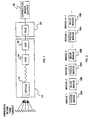
- FIG. 1 is a simplified schematic diagram of a missile tracking system with which the present invention is advantageously utilized.
- the tracking system includes a sensor 10 which produces an image.
- the sensor 10 includes optics 12 for collecting and focusing incident infrared energy from the ambient scene and target on the focal plane array 14, which produces an infrared image of the scene/area being tracked.
- the sensor 10 includes an analog-to-digital (A/D) convertor 16, which converts each of the n x n detector outputs into digital (numeric) values or pixels.
- A/D analog-to-digital
- the digitized images are processed in accordance with the invention by the adaptive non-uniformity compensation (NUC) processor 20 to provide corrected output images 30 in which scene artifacts have been reduced, and fixed pattern noise has been reduced or eliminated.
- the NUC processor 20 adjusts each pixel to compensate for the differing sensitivity of each detector in the FPA 14.
- the missile tracking system (not shown) then employs the corrected output images in the tracking of targets
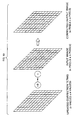
- FIG. 2 illustrates a sequence of images 1... n+1, alternating between a focussed image and a blurred image.
- the sensor output yields alternating focused and blurred images.
- the focus and blurring is controlled by the sensor optics 12.
- One exemplary way to achieve the focus and blurred images is to use a filter wheel in the sensor optics 12. The filter wheel spins, and has separate optics/lens to provide the focus image and the blurred image.
- the blurred images are used as part of the NUC process to help discriminate scene and target from FPN.
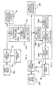
- FIG. 3 is a top level flow diagram illustrative of a first embodiment of the adaptive NUC process of the invention.
- the input image 18, which is either a focused image 18A or a blurred image 18B, is received from the sensor 10.
- the correction terms 26 are applied to the input image at step 22 to yield a corrected output image.
- the correction terms are initially zeros.
- the corrected output image 30 is passed both to the tracking system and to the NUC filter system 24.
- a different NUC filter is used for both the focused and blurred images. These two filters are described below.
- the filter system 24 updates the correction terms 26 based on the corrected output image.
- FIG. 4 illustrates the focused image processing for the filter system 24 of FIG. 3.
- the input focused image 18A is received from the sensor, and the correction terms 26 are applied at step 22 to yield the corrected focused image 30, as described above.
- the filter system 24 includes a focused image filter 24A, which includes the application of an anti-median filter 24C at step 24A1 to the corrected focused image to yield an anti-median image 30A.
- the image 30A is stored in memory for use on the following blurred image 18B.
- FIG. 5 is a flow diagram showing the blurred image processing for the filter system 24 of FIG. 3.
- the blurred image 18B is received from the sensor 10, and the correction terms 26 are applied at step 22 to provide the corrected blur image 30B, an output useful for diagnostics.
- the filter system 24 includes a blurred filter 24B which includes the application of the same anti-median filter 24C used in the focused filter 24A to the corrected blurred image.
- the output is compared to the filter output stored from the previous focus frame via a NUC comparison function 24B2, described more fully below.
- the output of the comparison function yields error terms which are used to update the correction terms for the next input focus image.
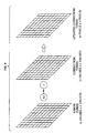
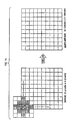
- FIGS. 6, 7A-7D and 8 illustrates the application of the anti-median filter 24C.
- the input image 18 is n pixels by n pixels in size. Each pixel has a numerical value representing brightness/intensity.
- the brightness/intensity values of X and two of its neighboring pixels are used to calculate a median value.
- the median is calculated by sorting the three pixels in ascending order of brightness/intensity values, and selecting the middle one of the sorted list to be the median. Two extra rows and columns of alternating Maximum (M) and minimum (m) values are added to the image to handle the boundary conditions.
- M Maximum
- m minimum
- the "anti-median” is a measure of how the pixel differs from the median.
- the result of the filtering is an n x n set 18D of anti-median values for the image 18.
- FIGS. 7A-7D There are four filter patterns, illustrated as patterns 1-4 in FIGS. 7A-7D, which are used in the filter system 24.
- the shaded areas represents pixels that are used in the median calculation; the center pixel is marked as "X.”
- the patterns are cycled, pattern 1 through pattern 4, for each successive pair of focus/blur image frames, as illustrated in FIG. 8.
- filter pattern 1 is used
- filter pattern 2 is used
- filter pattern 3 is used
- filter pattern 4 is used, with the filter pattern cycle starting again with images 9 and 10.
- the comparison function 24B2 (FIG. 5) is now described. Each value (row, column) of the anti-median image (focus) is compared to the corresponding value of the anti-median image (blur) as follows. Test 1: check whether the sign (+/-) of the anti-median focus is equal to the sign (+/-) of the anti-median blur. Test 2: check whether or not the anti-median blur is greater than some fraction (say, 3/4) of the anti-median focus. If Test 1 and Test 2 pass, then the error term is set equal to the anti-median focus; otherwise the error term is set to zero.
- the calculation of the anti-median can be positive or negative depending if the center pixel "X" is greater than or less than the median value. For example, assume that the median is 100 and the center pixel is 90. The anti-median would be equal to 100 minus 90, or positive 10. But if the center pixel was 115, then the anti-median would be equal to 100 minus 115 or -15 which is a negative value. The errors and the correction terms can be positive or negative. Positive values are used to correct pixels which are too dark. Negative values are used to correct pixels which are too bright.
- the comparison function 24B2 may be written in the following manner:
- the error terms are used to update the correction terms.
- Each Error Term (row,col) is multiplied by two and then added to the Correction Term (row,col) to yield updated Correction Terms.
- the Correction Terms are of higher precision than the image, the Correction Terms are divided by eight before they are added to the image.
- the "multiply Error Terms by two, divide by eight" functions result in a one quarter (1/4) correction of the estimated error.
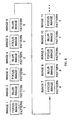
- the updating of the Corrections terms is illustrated diagrammatically in FIG. 9, which shows the Error Terms (n values x n values) being multiplied by 2, and added to the existing set of Correction Terms (n values x n values), to yield an updated set of Correction Terms (n pixels x n pixels).
- the Correction Terms are accumulated over many frames and stored with eight times the precision of the image. Each Correction Term is divided by eight and then added to the input image pixel (row,col) to yield a new pixel (row,col) in the output image. This is illustrated diagrammatically in FIG. 10, where the updated set of Correction Terms (n values x n values) is divided by eight, and added to the input image (n pixels x n pixels) to yield the corrected output image.
- FIG. 11 illustrates an alternate embodiment of the invention.
- An alternate NUC processor 20' applies the correction terms to the input image, and employs a NUC-II filter system 24' in the calculation of the Correction Terms.
- the input image 18 focused or blurred
- the Correction Terms are applied at 22 to the input image to yield a Corrected output image 30'.
- the Correction Terms are initially zero, and are applied in same manner as described above regarding the processor 20.
- the Corrected output image is passed to both the Tracking system and the NUC-II filter system 24'.
- a different NUC-II filter is used for focused and blurred images, as will be described in further detail below.
- the NUC filter system 24' updates the Correction Terms based on the Corrected output image 30'.
- FIG. 12 illustrates the focused image processing for the filter system 24' of FIG. 11.
- the input focused image 18A is received from the sensor, and the correction terms 26' are applied at step 22 to yield the corrected focused image 30', as described above.
- the filter system 24' includes a focused image filter 24A', which includes the application of an anti-mean filter 24C' at step 24A1' to the corrected focused image to yield an anti-mean image 30A'.
- the image 30A' is stored in memory for use on the following blurred image 18B.
- FIG. 13 is a flow diagram showing the blurred image processing for the filter system 24' of FIG. 11.
- the blurred image 18B is received from the sensor 10, and the correction terms 26' are applied at step 22 to provide the corrected blur image 30B', an output useful for diagnostics.
- the filter system 24' includes a blurred filter 24B' which includes the application of the same anti-mean filter 24C' used in the focused filter 24A' to the corrected blurred image.
- the output is compared to the filter output stored from the previous focus frame via a NUC-II comparison function 24B2', described more fully below.
- the output of the comparison function yields Error Terms which are used to update the Correction Terms for the next input focus image.
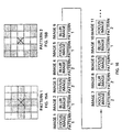
- FIGS. 14, 15A-15D and 16 illustrate the application of the anti-mean filter 24C'.
- the input image 18 is n pixels by n pixels in size.
- For each pixel X in the image the sum of X and its neighboring pixels indicated by the shaded regions in the filter mask is calculated. This sum is "Alpha-Trimmed” by subtracting the minimum and maximum pixel values contained within the filter mask. The mean is calculated by dividing the "Alpha-Trimmed" sum by number of pixels remaining in the sum. Filter mask pixels outside the image boundary are ignored in the calculation. This is illustrated by the location of the 13-pixel filter mask in FIG. 14, which illustrates the starting position for application to the n x n image.
- anti-mean is a measure of how the pixel differs from the mean.
- FIGS. 15A and 15B There are two filter patterns used for the NUC-II filter system 24', and are shown in FIGS. 15A and 15B.
- the shaded areas represent pixels that are used in the mean calculation, with the center pixel marked as an "X”.
- FIG. 16 shows the cycling of the filter patterns for each successive pair of focus/blur frames.
- the comparison function 242B' includes the following steps. Each value (row,col) of the anti-mean image (focus) is compared to the corresponding value of the anti-mean image (blur) as follows: Test 1: check whether the absolute value of the difference between the anti-mean focus and the anti-mean blur is less than or equal to 5. Test 2: determine if the absolute value of the anti-mean focus is less than the absolute value of the anti-mean blur. If Test 1 and Test 2 pass, then the error term is set to the anti-mean focus. If Test 1 passes but Test 2 fails, then the error term is set equal to the anti-mean blur. If Test 1 fails then the error term is set to zero and Test 2 is irrelevant.
- FIG. 17 diagrammatically illustrates the updating of the Correction Terms.
- Each error term (row,-col) is multiplied by a factor (F) based upon its magnitude and then added to the Correction Term (row,col) to yield updated Correction Terms.
- the factor (F) is calculated in the following manner.
- the absolute value of the Error Term is used to determine the factor (F) by which to multiply the Error Term. Say, for example, that the Error Terms have an absolute value range of zero (0) through 100. If the absolute value of the Error Term is 0 or 1, the factor (F) is set to 1. If the absolute value of the Error Term is 2 through 7, the factor (F) is set to 2. If the absolute value of the Error Term is 8 through 33, the factor (F) is set to 4. If the absolute value of the Error Term is 34 and greater, the factor (F) is set to 8. Because the Correction Terms are of higher precision than the image, they are divided by eight before they are added to the image. Therefore a factor (F) multiplier of 1 yields a correction of 1/8 of the error, 2 is 2/8 or 1/4, 4 is 4/8 or 1/2, and 8 is 8/8 or 1 which is a full correction.
- FPN is removed from focal plane array imagery by comparing the output of an anti-mean filter that is applied to both focused and optically blurred images. The comparison is done in such a way that scene artifacts are not created and subtle scene content is not destroyed. Because an anti-mean filter is used, FPN is removed even in the presence of shading. Shading can be caused by optics, blue-sky, and/or dome heating. The embodiment of FIG. 3 effectively "shuts off" in the presence of shading due to the use of an anti-median filter which preserves edges within the shading gradients.
Landscapes
- Engineering & Computer Science (AREA)
- Multimedia (AREA)
- Signal Processing (AREA)
- Physics & Mathematics (AREA)
- General Physics & Mathematics (AREA)
- Theoretical Computer Science (AREA)
- Image Processing (AREA)
- Transforming Light Signals Into Electric Signals (AREA)
- Investigating Or Analyzing Materials By The Use Of Electric Means (AREA)
- Measuring Fluid Pressure (AREA)
- Measuring Pulse, Heart Rate, Blood Pressure Or Blood Flow (AREA)
- Networks Using Active Elements (AREA)
- Photometry And Measurement Of Optical Pulse Characteristics (AREA)
- Picture Signal Circuits (AREA)
- Measurement Of Velocity Or Position Using Acoustic Or Ultrasonic Waves (AREA)
Claims (12)
- Anpassungsverfahren zur Beseitigung von Störungen mit festem Muster aus Fokalebenen-Abbildungsanordnungen (FPA), gekennzeichnet durch folgende Schritte:Erzeugen von jeweiligen fokussierten bzw. unscharfen digitalen Versionen (18A, 18B) eines FPA-Bildes (18);Einwirkenlassen (22) einer Gruppe von Korrekturausdrücken (26) auf die fokussierte Version des FPA-Bildes zur Erzeugung eines korrigierten, fokussierten FPA-Bildes;Einwirkenlassen einer Filterung (24C) auf die korrigierte, fokussierte Version des FPA-Bildes zur Erzeugung eines gefilterten, fokussierten Bildes;Einwirkenlassen der genannten Gruppe von Korrekturausdrücken auf die unscharfe Version des FPA-Bildes zur Erzeugung einer korrigierten unscharfen Version des FPA-Bildes;Einwirkenlassen der genannten Filterung auf das korrigierte, unscharfe Bild zur Erzeugung eines gefilterten, unscharfen Bildes;Errechnen von Festmuster-Störungsfehlern unter Verwendung des gefilterten, fokussierten Bildes und des gefilterten, unscharfen Bildes; undVerwenden der Festmuster-Störungsfehler zur Aktualisierung der Korrekturausdrücke zur Verwendung bei der Verarbeitung eines nächsten FPA-Bildes.
- Verfahren nach Anspruch 1, weiter dadurch gekennzeichnet, daß die genannte Filterung (24C) eine Filterung gegen einen Mittelwert umfaßt, welche für jedes Pixel in einem Bild einen entsprechenden Filterungswert gegenüber einem Mittelwert enthält, welcher ein Maß dafür ist, wie das Pixel von einem Mittelwert des Pixels und einer Gruppe von Nachbarpixeln abweicht.
- Verfahren nach Anspruch 2, weiter dadurch gekennzeichnet, daß die genannte Gruppe von Nachbarpixeln zwei Pixel auf gegenüberliegenden Seiten desjenigen Pixels umfaßt, dessen Filterungswert gegenüber dem Mittelwert zu errechnen ist.
- Verfahren nach Anspruch 3, weiter dadurch gekennzeichnet, daß der Schritt des Errechnens der genannten Festmuster-StöTfehlei das Addieren von begrenzenden Reihen und Spalten von Pixelwerten von abwechselnd maximalen und minimalen Pixelwerten zu dem korrigierten Ausgangsbild urnfaßt, um das genannte Ausgangsbild zu begrenzen und Umgrenzungsbedingunen zu berücksichtigen.
- Verfahren nach einem der Ansprüche 2 bis 4, weiter dadurch gekennzeichnet, daß der genannte Schritt der Errechnung der Festmuster-Störungsfehler den Vergleich entsprechender Werte des fokussierten Bildes und des unscharfen Bildes, sowie die Errechnung eines entsprechenden Fehlerausdrucks in Abhängigkeit von dem Vergleichsergebnis umfaßt.
- Verfahren nach Anspruch 1, weiter dadurch gekennzeichnet, daß die Filterung eine Filterung (24C') gegenüber einem Mittelwert umfaßt, welche für jedes Pixel in einem Bild einen entsprechenden Filterungswert gegenüber einem Mittelwert liefert, welcher ein Maß dafür ist, wie das betreffende Pixel sich von einem Mittelwert des Pixels und einer Gruppe von Nachbarpixeln unterscheidet.
- Verfahren nach Anspruch 6, weiter dadurch gekennzeichnet, daß die genannte Gruppe von Nachbarpixeln eine solche Gruppe von Nachbarpixel uinfaßt, bei welcher Pixel in der Gruppe mit maximalen und minimalen Werten von der Errechnung des genannten Mittelwertes ausgeschlossen werden.
- Verfahren nach Anspruch 6 oder Anspruch 7, weiter dadurch gekennzeichnet, daß der Schritt des Errechnens der Festmuster-Störungsfehler das Vergleichen entsprechender Werte des fokussierten Bildes und des unscharfen Bildes, sowie die Errechnung eines entsprechenden Fehlerausdrucks in Abhängigkeit vom Vergleichsergebnis umfaßt.
- Verfahren nach einem der vorhergehenden Ansprüche, weiter dadurch gekennzeichnet, daß das FPA-Bild (18) ein Infrarotbild ist.
- Adaptiver Sensor in einem Ungleichförmigkeits-Kompensationssystem zur Erzeugung eines korrigierten Ausgangsbildes aus einem Bild einer Fokalebenen-Abbildungsanordnung (FPA), wobei die Störungen mit festem Muster in der Fokalebenen-Abbildungsanordnung (FPA) kompensiert worden sind und wobei der Sensor folgendes enthält:eine zu einem Sensor (10) gehörige Sensoroptik (12), eine Fokalebenen-Anordnung (14) von Infrarotdetektoren zur Erzeugung von FPA-Bildern, sowie eine Analog-/Digital-Umformereinrichtung (16) zur Umwandlung der FPA-Bilder in digitalisierte FPA-Bilder, welche eine Gruppe von Pixelwerten umfassen, wobei die Sensoroptik so ausgebildet ist, daß sie fokussierte und unscharfe Versionen des Bildes liefert;einen adaptiven Ungleichförmigkeits-Kompensationsprozessor (20) zum Kompensieren von Ungleichförmigkeiten der Empfindlichkeiten der Infrarotdetektoren gegenüber Infrarotstrahlung, wobei der Prozessor jeden Pixelwert im Sinne einer Kompensation unterschiedlicher Empfindlichkeit des jeweiligen Detektors in der FPA-Anordnung einstellt und ein korrigiertes Ausgangsbild liefert, und wobei der Prozessor folgendes enthält:erste Mittel (22) zum Einwirkenlassen einer Gruppe von Korrekturausdrücken (26) auf eine fokussierte Version (18A) des FPA-Bildes zur Erzeugung eines korrigierten, fokussierten FPA-Bildes (30);ein erstes Filtersystem (24A) zur Vornahme einer Filterung (24C) an der korrigierten, fokussierten Version des FPA-Bildes zur Erzeugung eines gefilterten, fokussierten Bildes;zweite Mittel zum Einwirkenlassen der genannten Gruppe von Korrekturausdrücken auf die unscharfe Version des FPA-Bildes zur Erzeugung einer korrigierten, unscharfen Version des FPA-Bildes;ein zweites Filtersystem (248) zur Vornahme einer Filterung an dern korrigierten, unscharfen Bild zur Erzeugung eines gefilterten, unscharfen Bildes;dritte Mittel zur Errechnung von Festmuster-Störungsfehlern unter Verwendung des gefilterten, fokussierten Bildes und des gefilterten, unscharfen Bildes; undvierte Mittel zur Verwendung der genannten Festmuster-Störungsfehler zur Aktualisierung der Korrekturausdrücke für die Verwendung bei der Verarbeitung des nächsten FPA-Bildes.
- System nach Anspruch 10, weiter dadurch gekennzeichnet, daß die genannte Filterung (24) eine Filterung (24C) gegenüber einem Mittelwert umfaßt, welche für jedes Pixel in einem Bild einen entsprechenden Wert gegenüber einem Mittelwert liefert, der ein Maß dafür ist, wie das Pixel sich von einem Mittelwert dieses Pixels und einer Gruppe von Nachbarpixeln unterscheidet.
- System nach Anspruch 10, weiter dadurch gekennzeichnet, daß die genannte Filterung eine Filterung (24C') gegenüber einem Mittelwert umfaßt, welche für jedes Pixel in einem Bild einen entsprechenden Wert gegenüber einem Mittelwert liefert, der ein Maß dafür ist, wie sich das betreffende Pixel von einem Mittelwert dieses Pixel und einer Gruppe von Nachbarpixeln unterscheidet.
Applications Claiming Priority (3)
| Application Number | Priority Date | Filing Date | Title |
|---|---|---|---|
| US08/843,874 US5903659A (en) | 1997-04-17 | 1997-04-17 | Adaptive non-uniformity compensation algorithm |
| US843874 | 1997-04-17 | ||
| PCT/US1998/007755 WO1998047102A2 (en) | 1997-04-17 | 1998-04-15 | Adaptive non-uniformity compensation algorithm |
Publications (2)
| Publication Number | Publication Date |
|---|---|
| EP0909428A2 EP0909428A2 (de) | 1999-04-21 |
| EP0909428B1 true EP0909428B1 (de) | 2001-07-25 |
Family
ID=25291211
Family Applications (1)
| Application Number | Title | Priority Date | Filing Date |
|---|---|---|---|
| EP98939058A Expired - Lifetime EP0909428B1 (de) | 1997-04-17 | 1998-04-15 | Adaptiver non-uniformer kompensierungsverfahren und sensor |
Country Status (15)
| Country | Link |
|---|---|
| US (1) | US5903659A (de) |
| EP (1) | EP0909428B1 (de) |
| JP (1) | JP3417573B2 (de) |
| KR (1) | KR100315897B1 (de) |
| AT (1) | ATE203610T1 (de) |
| AU (1) | AU705782B2 (de) |
| CA (1) | CA2254143C (de) |
| DE (1) | DE69801201T2 (de) |
| DK (1) | DK0909428T3 (de) |
| IL (1) | IL127240A (de) |
| NO (1) | NO316849B1 (de) |
| NZ (1) | NZ332877A (de) |
| TR (1) | TR199802636T1 (de) |
| TW (1) | TW517192B (de) |
| WO (1) | WO1998047102A2 (de) |
Cited By (1)
| Publication number | Priority date | Publication date | Assignee | Title |
|---|---|---|---|---|
| WO2008091356A3 (en) * | 2006-08-29 | 2008-10-02 | Raytheon Co | System and method for adaptive non-uniformity compensation for a focal plane array |
Families Citing this family (57)
| Publication number | Priority date | Publication date | Assignee | Title |
|---|---|---|---|---|
| KR100306419B1 (en) * | 1997-11-29 | 2001-08-09 | Samsung Electronics Co Ltd | Method for correcting shading of shuttle scanner |
| US6714240B1 (en) * | 1998-06-23 | 2004-03-30 | Boeing North American, Inc. | Optical sensor employing motion compensated integration-device and process |
| US6211515B1 (en) * | 1998-10-19 | 2001-04-03 | Raytheon Company | Adaptive non-uniformity compensation using feedforward shunting and wavelet filter |
| US6243498B1 (en) * | 1998-10-19 | 2001-06-05 | Raytheon Company | Adaptive non-uniformity compensation using feedforwarding shunting |
| US6330371B1 (en) * | 1998-10-19 | 2001-12-11 | Raytheon Company | Adaptive non-uniformity compensation using feedforward shunting and min-mean filter |
| US7035475B1 (en) | 1999-06-17 | 2006-04-25 | Raytheon Company | Non-traditional adaptive non-uniformity compensation (ADNUC) system employing adaptive feedforward shunting and operating methods therefor |
| JP2001069353A (ja) * | 1999-08-24 | 2001-03-16 | Fuji Photo Film Co Ltd | 画像処理装置 |
| EP1332347A4 (de) | 2000-10-13 | 2006-05-03 | Litton Systems Inc | System und verfahren zum erzeugen von signalen |
| US6541772B2 (en) | 2000-12-26 | 2003-04-01 | Honeywell International Inc. | Microbolometer operating system |
| US6559447B2 (en) | 2000-12-26 | 2003-05-06 | Honeywell International Inc. | Lightweight infrared camera |
| US7365326B2 (en) * | 2000-12-26 | 2008-04-29 | Honeywell International Inc. | Camera having distortion correction |
| US20030007089A1 (en) * | 2001-01-12 | 2003-01-09 | Anteon Corporation | Opto-electronic video compression system |
| US7103235B2 (en) * | 2001-04-25 | 2006-09-05 | Lockheed Martin Corporation | Extended range image processing for electro-optical systems |
| US7016550B2 (en) * | 2002-04-19 | 2006-03-21 | Lockheed Martin Corporation | Scene-based non-uniformity offset correction for staring arrays |
| US6901173B2 (en) * | 2001-04-25 | 2005-05-31 | Lockheed Martin Corporation | Scene-based non-uniformity correction for detector arrays |
| US6973218B2 (en) * | 2001-04-25 | 2005-12-06 | Lockheed Martin Corporation | Dynamic range compression |
| US7119837B2 (en) * | 2002-06-28 | 2006-10-10 | Microsoft Corporation | Video processing system and method for automatic enhancement of digital video |
| EP1704510A4 (de) * | 2003-12-31 | 2009-09-09 | Lockheed Martin Missiles & Fir | Verfahren und system zur adaptiven zieldetektion |
| US7463753B2 (en) * | 2004-09-15 | 2008-12-09 | Raytheon Company | FLIR-to-missile boresight correlation and non-uniformity compensation of the missile seeker |
| US7899271B1 (en) | 2004-09-15 | 2011-03-01 | Raytheon Company | System and method of moving target based calibration of non-uniformity compensation for optical imagers |
| US8153978B1 (en) * | 2006-03-08 | 2012-04-10 | Oceanit Laboratories, Inc. | Dual color/dual function focal plane |
| US8164061B2 (en) * | 2006-09-13 | 2012-04-24 | Delphi Technologies, Inc. | Method and apparatus for a universal infrared analyzer |
| US20080212895A1 (en) * | 2007-01-09 | 2008-09-04 | Lockheed Martin Corporation | Image data processing techniques for highly undersampled images |
| EP2105009A1 (de) * | 2007-01-16 | 2009-09-30 | Robert Bosch GmbH | Bildverbesserungseinrichtung, prozess zur bildverbesserung und computerprogramm |
| US7920982B2 (en) * | 2008-01-15 | 2011-04-05 | Raytheon Company | Optical distortion calibration for electro-optical sensors |
| US7649174B2 (en) * | 2008-02-11 | 2010-01-19 | Flir Systems, Inc. | Thermography camera configured for gas leak detection |
| US8158928B2 (en) * | 2008-12-23 | 2012-04-17 | Fluke Corporation | System and method for improving the quality of thermal images |
| US9635285B2 (en) | 2009-03-02 | 2017-04-25 | Flir Systems, Inc. | Infrared imaging enhancement with fusion |
| US9843742B2 (en) | 2009-03-02 | 2017-12-12 | Flir Systems, Inc. | Thermal image frame capture using de-aligned sensor array |
| US9756264B2 (en) | 2009-03-02 | 2017-09-05 | Flir Systems, Inc. | Anomalous pixel detection |
| US9237284B2 (en) | 2009-03-02 | 2016-01-12 | Flir Systems, Inc. | Systems and methods for processing infrared images |
| US9235876B2 (en) | 2009-03-02 | 2016-01-12 | Flir Systems, Inc. | Row and column noise reduction in thermal images |
| US9948872B2 (en) * | 2009-03-02 | 2018-04-17 | Flir Systems, Inc. | Monitor and control systems and methods for occupant safety and energy efficiency of structures |
| US9208542B2 (en) | 2009-03-02 | 2015-12-08 | Flir Systems, Inc. | Pixel-wise noise reduction in thermal images |
| SE533650C2 (sv) | 2009-04-22 | 2010-11-16 | Flir Systems Ab | Bildbehandlingsmetod för undertryckande av kolumn- eller radbrus i en IR-detekterad bild |
| US9243960B2 (en) | 2009-04-30 | 2016-01-26 | Ulis | System and method for detecting infrared radiation |
| FR2945120B1 (fr) | 2009-04-30 | 2015-11-27 | Ulis | Systeme et procede de detection de rayonnement infrarouge |
| US10091439B2 (en) | 2009-06-03 | 2018-10-02 | Flir Systems, Inc. | Imager with array of multiple infrared imaging modules |
| US9843743B2 (en) | 2009-06-03 | 2017-12-12 | Flir Systems, Inc. | Infant monitoring systems and methods using thermal imaging |
| US8738678B2 (en) | 2009-10-29 | 2014-05-27 | Raytheon Company | Methods and systems for determining an enhanced rank order value of a data set |
| US8416986B2 (en) * | 2009-10-29 | 2013-04-09 | Raytheon Company | Methods and systems for processing data using non-linear slope compensation |
| JP2012100116A (ja) * | 2010-11-02 | 2012-05-24 | Sony Corp | 表示処理装置、表示処理方法およびプログラム |
| US8625005B2 (en) * | 2010-11-05 | 2014-01-07 | Raytheon Company | First-in-first-out (FIFO) buffered median scene non-uniformity correction method |
| US20130278771A1 (en) * | 2011-06-10 | 2013-10-24 | Flir Systems, Inc. | Systems and methods for monitoring vehicle wheel assembly |
| US10051210B2 (en) * | 2011-06-10 | 2018-08-14 | Flir Systems, Inc. | Infrared detector array with selectable pixel binning systems and methods |
| EP2719165B1 (de) | 2011-06-10 | 2018-05-02 | Flir Systems, Inc. | Ungleichmässigkeitskorrekturverfahren für infrarot-bildgebungsvorrichtungen |
| EP2579009A1 (de) | 2011-10-06 | 2013-04-10 | Ulis | System und Verfahren zur Erfassung von Infrarotstrahlung |
| WO2014012070A1 (en) * | 2012-07-12 | 2014-01-16 | Flir Systems, Inc. | Infant monitoring systems and methods using thermal imaging |
| CN104813652B (zh) * | 2012-09-18 | 2018-03-09 | 菲力尔系统公司 | 热图像中的像素的降噪 |
| JP6337131B2 (ja) | 2014-09-30 | 2018-06-06 | 富士フイルム株式会社 | 赤外線撮像装置、固定パターンノイズ算出方法、及び固定パターンノイズ算出プログラム |
| JP6291629B2 (ja) * | 2015-05-21 | 2018-03-14 | 富士フイルム株式会社 | 赤外線撮像装置及び固定パターンノイズデータの更新方法 |
| US11113791B2 (en) | 2017-01-03 | 2021-09-07 | Flir Systems, Inc. | Image noise reduction using spectral transforms |
| US10453187B2 (en) | 2017-07-21 | 2019-10-22 | The Boeing Company | Suppression of background clutter in video imagery |
| US10438326B2 (en) * | 2017-07-21 | 2019-10-08 | The Boeing Company | Recursive suppression of clutter in video imagery |
| US10437132B1 (en) | 2018-03-20 | 2019-10-08 | Raytheon Company | Methods and apparatus for acousto-optic non-uniformity correction and counter-countermeasure mechanisms |
| US11611692B2 (en) * | 2020-11-09 | 2023-03-21 | Rockwell Collins, Inc. | Fixed pattern noise reduction and high spatial frequency filtering using vari-focus lenses in low contrast scenes |
| KR102593550B1 (ko) * | 2020-11-12 | 2023-10-25 | 인트플로우 주식회사 | 체온측정을 위한 온도정보보정방법 |
Family Cites Families (6)
| Publication number | Priority date | Publication date | Assignee | Title |
|---|---|---|---|---|
| US3987243A (en) * | 1975-11-03 | 1976-10-19 | Sanders Associates, Inc. | Image enhancement method and apparatus |
| US4975864A (en) * | 1989-01-26 | 1990-12-04 | Hughes Aircraft Company | Scene based nonuniformity compensation for starting focal plane arrays |
| US5307175A (en) * | 1992-03-27 | 1994-04-26 | Xerox Corporation | Optical image defocus correction |
| US5373151A (en) * | 1993-10-04 | 1994-12-13 | Raytheon Company | Optical system including focal plane array compensation technique for focusing and periodically defocusing a beam |
| US5400161A (en) * | 1993-10-04 | 1995-03-21 | Raytheon Company | Optical system including focus-defocus focal plane array compensation technique using liquid crystal phased array |
| US5471240A (en) * | 1993-11-15 | 1995-11-28 | Hughes Aircraft Company | Nonuniformity correction of an imaging sensor using region-based correction terms |
-
1997
- 1997-04-17 US US08/843,874 patent/US5903659A/en not_active Expired - Lifetime
-
1998
- 1998-04-15 AT AT98939058T patent/ATE203610T1/de not_active IP Right Cessation
- 1998-04-15 DK DK98939058T patent/DK0909428T3/da active
- 1998-04-15 KR KR1019980710359A patent/KR100315897B1/ko not_active Expired - Fee Related
- 1998-04-15 CA CA002254143A patent/CA2254143C/en not_active Expired - Fee Related
- 1998-04-15 EP EP98939058A patent/EP0909428B1/de not_active Expired - Lifetime
- 1998-04-15 JP JP54432798A patent/JP3417573B2/ja not_active Expired - Fee Related
- 1998-04-15 AU AU87562/98A patent/AU705782B2/en not_active Ceased
- 1998-04-15 NZ NZ332877A patent/NZ332877A/en unknown
- 1998-04-15 IL IL12724098A patent/IL127240A/en not_active IP Right Cessation
- 1998-04-15 TR TR1998/02636T patent/TR199802636T1/xx unknown
- 1998-04-15 WO PCT/US1998/007755 patent/WO1998047102A2/en not_active Ceased
- 1998-04-15 DE DE69801201T patent/DE69801201T2/de not_active Expired - Lifetime
- 1998-06-26 TW TW087105981A patent/TW517192B/zh not_active IP Right Cessation
- 1998-12-16 NO NO19985898A patent/NO316849B1/no not_active IP Right Cessation
Cited By (2)
| Publication number | Priority date | Publication date | Assignee | Title |
|---|---|---|---|---|
| WO2008091356A3 (en) * | 2006-08-29 | 2008-10-02 | Raytheon Co | System and method for adaptive non-uniformity compensation for a focal plane array |
| AU2007345299B2 (en) * | 2006-08-29 | 2010-06-17 | Raytheon Company | System and method for adaptive non-uniformity compensation for a focal plane array |
Also Published As
| Publication number | Publication date |
|---|---|
| JP3417573B2 (ja) | 2003-06-16 |
| WO1998047102A2 (en) | 1998-10-22 |
| AU705782B2 (en) | 1999-06-03 |
| JP2001509996A (ja) | 2001-07-24 |
| NO985898L (no) | 1999-02-15 |
| DE69801201D1 (de) | 2001-08-30 |
| ATE203610T1 (de) | 2001-08-15 |
| KR100315897B1 (ko) | 2002-01-24 |
| NZ332877A (en) | 2000-06-23 |
| US5903659A (en) | 1999-05-11 |
| NO316849B1 (no) | 2004-06-01 |
| WO1998047102A9 (en) | 1999-04-22 |
| KR20000016752A (ko) | 2000-03-25 |
| IL127240A (en) | 2002-12-01 |
| DK0909428T3 (da) | 2001-09-24 |
| TR199802636T1 (xx) | 2001-09-21 |
| WO1998047102A3 (en) | 1999-01-21 |
| NO985898D0 (no) | 1998-12-16 |
| EP0909428A2 (de) | 1999-04-21 |
| TW517192B (en) | 2003-01-11 |
| AU8756298A (en) | 1998-11-11 |
| CA2254143C (en) | 2002-12-17 |
| IL127240A0 (en) | 1999-09-22 |
| CA2254143A1 (en) | 1998-10-22 |
| DE69801201T2 (de) | 2002-05-16 |
Similar Documents
| Publication | Publication Date | Title |
|---|---|---|
| EP0909428B1 (de) | Adaptiver non-uniformer kompensierungsverfahren und sensor | |
| KR101379075B1 (ko) | 초점면 어레이에 대한 적응적 비-균일성 보상을 위한 시스템 및 방법 | |
| US4532548A (en) | Resolution enhancement and zoom | |
| US6330371B1 (en) | Adaptive non-uniformity compensation using feedforward shunting and min-mean filter | |
| AU2013314015B2 (en) | Moving object detection method | |
| US7035475B1 (en) | Non-traditional adaptive non-uniformity compensation (ADNUC) system employing adaptive feedforward shunting and operating methods therefor | |
| US6243498B1 (en) | Adaptive non-uniformity compensation using feedforwarding shunting | |
| JP7414538B2 (ja) | 撮像装置及びその制御方法 | |
| Schwarz et al. | MAR: A Multiband Astronomical Reduction package | |
| Stobie et al. | NICMOS Software: An Observation Case Study | |
| NO167243B (no) | Avbildningssystem og fremgangsmaate for bildeopploesningsoekning i et avbildningssystem. |
Legal Events
| Date | Code | Title | Description |
|---|---|---|---|
| PUAI | Public reference made under article 153(3) epc to a published international application that has entered the european phase |
Free format text: ORIGINAL CODE: 0009012 |
|
| 17P | Request for examination filed |
Effective date: 19990111 |
|
| AK | Designated contracting states |
Kind code of ref document: A2 Designated state(s): AT BE CH DE DK ES FR GB GR IT LI NL SE |
|
| RTI1 | Title (correction) |
Free format text: ADAPTIVE NON-UNIFORMITY COMPENSATION METHOD AND SENSOR |
|
| GRAG | Despatch of communication of intention to grant |
Free format text: ORIGINAL CODE: EPIDOS AGRA |
|
| 17Q | First examination report despatched |
Effective date: 19991111 |
|
| GRAG | Despatch of communication of intention to grant |
Free format text: ORIGINAL CODE: EPIDOS AGRA |
|
| GRAH | Despatch of communication of intention to grant a patent |
Free format text: ORIGINAL CODE: EPIDOS IGRA |
|
| GRAH | Despatch of communication of intention to grant a patent |
Free format text: ORIGINAL CODE: EPIDOS IGRA |
|
| GRAA | (expected) grant |
Free format text: ORIGINAL CODE: 0009210 |
|
| AK | Designated contracting states |
Kind code of ref document: B1 Designated state(s): AT BE CH DE DK ES FR GB GR IT LI NL SE |
|
| PG25 | Lapsed in a contracting state [announced via postgrant information from national office to epo] |
Ref country code: NL Free format text: LAPSE BECAUSE OF FAILURE TO SUBMIT A TRANSLATION OF THE DESCRIPTION OR TO PAY THE FEE WITHIN THE PRESCRIBED TIME-LIMIT Effective date: 20010725 Ref country code: LI Free format text: LAPSE BECAUSE OF FAILURE TO SUBMIT A TRANSLATION OF THE DESCRIPTION OR TO PAY THE FEE WITHIN THE PRESCRIBED TIME-LIMIT Effective date: 20010725 Ref country code: IT Free format text: LAPSE BECAUSE OF FAILURE TO SUBMIT A TRANSLATION OF THE DESCRIPTION OR TO PAY THE FEE WITHIN THE PRESCRIBED TIME-LIMIT;WARNING: LAPSES OF ITALIAN PATENTS WITH EFFECTIVE DATE BEFORE 2007 MAY HAVE OCCURRED AT ANY TIME BEFORE 2007. THE CORRECT EFFECTIVE DATE MAY BE DIFFERENT FROM THE ONE RECORDED. Effective date: 20010725 Ref country code: FR Free format text: LAPSE BECAUSE OF FAILURE TO SUBMIT A TRANSLATION OF THE DESCRIPTION OR TO PAY THE FEE WITHIN THE PRESCRIBED TIME-LIMIT Effective date: 20010725 Ref country code: CH Free format text: LAPSE BECAUSE OF FAILURE TO SUBMIT A TRANSLATION OF THE DESCRIPTION OR TO PAY THE FEE WITHIN THE PRESCRIBED TIME-LIMIT Effective date: 20010725 Ref country code: AT Free format text: LAPSE BECAUSE OF FAILURE TO SUBMIT A TRANSLATION OF THE DESCRIPTION OR TO PAY THE FEE WITHIN THE PRESCRIBED TIME-LIMIT Effective date: 20010725 |
|
| REF | Corresponds to: |
Ref document number: 203610 Country of ref document: AT Date of ref document: 20010815 Kind code of ref document: T |
|
| REG | Reference to a national code |
Ref country code: CH Ref legal event code: EP |
|
| REF | Corresponds to: |
Ref document number: 69801201 Country of ref document: DE Date of ref document: 20010830 |
|
| REG | Reference to a national code |
Ref country code: DK Ref legal event code: T3 |
|
| PG25 | Lapsed in a contracting state [announced via postgrant information from national office to epo] |
Ref country code: GR Free format text: LAPSE BECAUSE OF FAILURE TO SUBMIT A TRANSLATION OF THE DESCRIPTION OR TO PAY THE FEE WITHIN THE PRESCRIBED TIME-LIMIT Effective date: 20011026 |
|
| EN | Fr: translation not filed | ||
| REG | Reference to a national code |
Ref country code: GB Ref legal event code: IF02 |
|
| NLV1 | Nl: lapsed or annulled due to failure to fulfill the requirements of art. 29p and 29m of the patents act | ||
| PG25 | Lapsed in a contracting state [announced via postgrant information from national office to epo] |
Ref country code: ES Free format text: LAPSE BECAUSE OF FAILURE TO SUBMIT A TRANSLATION OF THE DESCRIPTION OR TO PAY THE FEE WITHIN THE PRESCRIBED TIME-LIMIT Effective date: 20020131 |
|
| REG | Reference to a national code |
Ref country code: CH Ref legal event code: PL |
|
| PLBE | No opposition filed within time limit |
Free format text: ORIGINAL CODE: 0009261 |
|
| STAA | Information on the status of an ep patent application or granted ep patent |
Free format text: STATUS: NO OPPOSITION FILED WITHIN TIME LIMIT |
|
| 26N | No opposition filed | ||
| PGFP | Annual fee paid to national office [announced via postgrant information from national office to epo] |
Ref country code: DK Payment date: 20120411 Year of fee payment: 15 Ref country code: DE Payment date: 20120425 Year of fee payment: 15 Ref country code: BE Payment date: 20120412 Year of fee payment: 15 |
|
| PGFP | Annual fee paid to national office [announced via postgrant information from national office to epo] |
Ref country code: SE Payment date: 20120411 Year of fee payment: 15 Ref country code: GB Payment date: 20120411 Year of fee payment: 15 |
|
| BERE | Be: lapsed |
Owner name: *RAYTHEON CY Effective date: 20130430 |
|
| REG | Reference to a national code |
Ref country code: SE Ref legal event code: EUG |
|
| REG | Reference to a national code |
Ref country code: DK Ref legal event code: EBP Effective date: 20130430 |
|
| GBPC | Gb: european patent ceased through non-payment of renewal fee |
Effective date: 20130415 |
|
| PG25 | Lapsed in a contracting state [announced via postgrant information from national office to epo] |
Ref country code: SE Free format text: LAPSE BECAUSE OF NON-PAYMENT OF DUE FEES Effective date: 20130416 Ref country code: BE Free format text: LAPSE BECAUSE OF NON-PAYMENT OF DUE FEES Effective date: 20130430 Ref country code: DE Free format text: LAPSE BECAUSE OF NON-PAYMENT OF DUE FEES Effective date: 20131101 Ref country code: GB Free format text: LAPSE BECAUSE OF NON-PAYMENT OF DUE FEES Effective date: 20130415 |
|
| REG | Reference to a national code |
Ref country code: DE Ref legal event code: R119 Ref document number: 69801201 Country of ref document: DE Effective date: 20131101 |
|
| PG25 | Lapsed in a contracting state [announced via postgrant information from national office to epo] |
Ref country code: DK Free format text: LAPSE BECAUSE OF NON-PAYMENT OF DUE FEES Effective date: 20130430 |