EP0908797A2 - Electronic watch - Google Patents
Electronic watch Download PDFInfo
- Publication number
- EP0908797A2 EP0908797A2 EP98204248A EP98204248A EP0908797A2 EP 0908797 A2 EP0908797 A2 EP 0908797A2 EP 98204248 A EP98204248 A EP 98204248A EP 98204248 A EP98204248 A EP 98204248A EP 0908797 A2 EP0908797 A2 EP 0908797A2
- Authority
- EP
- European Patent Office
- Prior art keywords
- dynamo
- wheel train
- wall portion
- electronic watch
- wheel
- Prior art date
- Legal status (The legal status is an assumption and is not a legal conclusion. Google has not performed a legal analysis and makes no representation as to the accuracy of the status listed.)
- Granted
Links
Images


Classifications
-
- G—PHYSICS
- G04—HOROLOGY
- G04B—MECHANICALLY-DRIVEN CLOCKS OR WATCHES; MECHANICAL PARTS OF CLOCKS OR WATCHES IN GENERAL; TIME PIECES USING THE POSITION OF THE SUN, MOON OR STARS
- G04B5/00—Automatic winding up
- G04B5/02—Automatic winding up by self-winding caused by the movement of the watch
- G04B5/16—Construction of the weights
-
- G—PHYSICS
- G04—HOROLOGY
- G04B—MECHANICALLY-DRIVEN CLOCKS OR WATCHES; MECHANICAL PARTS OF CLOCKS OR WATCHES IN GENERAL; TIME PIECES USING THE POSITION OF THE SUN, MOON OR STARS
- G04B31/00—Bearings; Point suspensions or counter-point suspensions; Pivot bearings; Single parts therefor
- G04B31/004—Bearings; Point suspensions or counter-point suspensions; Pivot bearings; Single parts therefor characterised by the material used
- G04B31/012—Metallic bearings
- G04B31/0123—Metallic bearings with metallic ball bearings and metallic roller bearings
-
- G—PHYSICS
- G04—HOROLOGY
- G04B—MECHANICALLY-DRIVEN CLOCKS OR WATCHES; MECHANICAL PARTS OF CLOCKS OR WATCHES IN GENERAL; TIME PIECES USING THE POSITION OF THE SUN, MOON OR STARS
- G04B31/00—Bearings; Point suspensions or counter-point suspensions; Pivot bearings; Single parts therefor
- G04B31/08—Lubrication
-
- G—PHYSICS
- G04—HOROLOGY
- G04C—ELECTROMECHANICAL CLOCKS OR WATCHES
- G04C10/00—Arrangements of electric power supplies in time pieces
-
- G—PHYSICS
- G04—HOROLOGY
- G04C—ELECTROMECHANICAL CLOCKS OR WATCHES
- G04C3/00—Electromechanical clocks or watches independent of other time-pieces and in which the movement is maintained by electric means
- G04C3/008—Mounting, assembling of components
Abstract

Description
- The present invention relates to an electronic watch including a so-called automatic winding dynamo, and more particularly to a technology for improving the structure of such an electronic watch to achieve a reduction in thickness.
- In a so-called electronic watch using a crystal oscillator or the like as a time base, as shown in Fig. 1, a
power supply section 10 is made up of a small-sizeddynamo 20 and asecondary power supply 30, and astepping motor 40 is driven by power supplied from thepower supply section 10. Awatch wheel train 50 is operatively connected to amotor rotor 42 of thestepping motor 40 so that, for example, asecond hand 161 attached to asecond wheel 52 is intermittently rotated in steps of 6° for each second. - On the other hand, the small-
sized dynamo 20 comprises adynamo rotor 21 rotated by torque transmitted to it, adynamo stator 22 disposed in surrounding relation to thedynamo rotor 21, and adynamo coil 23 wound over amagnetic core 24 making up a magnetic circuit in cooperation with thedynamo stator 22 and thedynamo rotor 21. Adynamo wheel train 60 for transmitting rotation of a oscillatingweight 25 while speeding up the rotation is operatively connected to thedynamo rotor 21. - In the field of electronic watches with hands, there is a strong demand for a reduction in thickness even in the above-mentioned type having a small-sized dynamo. However, such a demand for a reduction in thickness cannot be satisfied simply by reducing the size or thickness of various parts, e.g., the oscillating
weight 25 as one component of the small-sized dynamo. For example, if the thickness of the oscillatingweight 25 is reduced, weight unbalance of the oscillatingweight 25 in the angular direction would be diminished and the oscillatingweight 25 would be hard to rotate at a high speed. Also, because necessary parts are mounted on acircuit board 31 constituting a circuit section, the circuit section cannot be further reduced in size and thickness. If it is nonetheless attempted to reduce a space in which the circuit section is installed, there would occur a risk that electronic parts and so forth may interfere with gears of thedynamo wheel train 60 and thewatch wheel train 50. - A rotational shaft of the
dynamo rotor 21 and a rotational shaft of thedynamo wheel train 60 are each often supported by a small and simple bearing formed of a hole jewel. In the bearing structure using a hole jewel, however, a lubricant applied to the rotational shaft tends to scatter to the surroundings upon rotation of the rotational shaft. If the scattered lubricant adheres to thewatch wheel train 50, the lubricant may cause abnormal motion in driving the hands, such as stop or delay of any of gears, due to its viscosity. This raises a problem in the conventional electronic watches with hands that the parts cannot be arranged in closer relation and hence the thickness of the watch cannot be reduced. - Further, in the conventional electronic watches with hands, as shown in Fig. 11, one of the gears of the dynamo wheel train which tends to be easily subject to lateral pressure, such as a dynamo rotor transmitting
wheel 62A (see Fig. 1), is sometimes supported at its rotational shaft 20A by a ball bearing 28A. The ball bearing 28A comprises a plurality ofballs 281A arranged around therotational shaft 620A of the dynamo rotor transmittingwheel 62A, a ring-shaped frame piece 282A holding theballs 281A, and aretainer piece 283A positioned adjacent theframe piece 282A to cooperate with it to prevent theballs 281A from slipping off. Theballs 281A are held in contact with therotational shaft 620A to restrict a lateral inclination of therotational shaft 620A. Also, therotational shaft 620A has astepped portion 626A formed around it, and thestepped portion 626A abuts against theretainer piece 283A to restrict the position of therotational shaft 620A in the axial direction. - However, the bearing structure shown in Fig. 11 has a problem that large friction resistance generates between the
stepped portion 626A and theretainer piece 283A when therotational shaft 620A is rotated. Generation of large friction resistance means that wasteful excessive force is required to rotate therotational shaft 620A, and that thestepped portion 626A or theretainer piece 283A is severely worn away. Thus, there is a need for a novel bearing structure capable of solving the above-stated problems. However, even a bearing structure which has succeeded in solving the above-stated problems cannot be practically adopted if it requires a larger space, because such a bearing structure prevents a reduction in thickness of electronic watches with hands. - In view of the problems stated above, an object of the present invention is to provide a construction of an electronic watch with a built-in dynamo, which can improve structures of parts themselves arranged inside the watch and layout of the parts, and can reduce a total thickness of the electronic watch.
- According to the present invention, there is provided an electronic watch having a base on which are mounted a dynamo including a dynamo wheel train for transmitting external force to a dynamo rotor, a secondary power supply for storing electric energy generated by said dynamo, a circuit section including a driving circuit supplied with power from said secondary power supply, a stepping motor driven by said driving circuit, and a watch wheel train for transmitting torque from said stepping motor to a time indicating member, wherein:
- said electronic watch includes an oscillating weight for transmitting external force to said dynamo rotor through said dynamo wheel train, said oscillating weight comprising a rotating central portion supported by said base, a thinner wall portion formed around said rotating central portion, and a thicker wall portion formed around said thinner wall portion,
- said watch wheel train and said dynamo wheel train are arranged on said base in a rotating area of said thinner wall portion, and
- a part of said circuit section which is positioned in a rotating area of said thicker wall portion is arranged in a circuit part installation hole defined in said base in the form of a recess or a though-hole.
-
- In the present invention, the part of the circuit section which is arranged in the circuit part installation holes in the rotating area of the thicker wall portion is an electronic part making up the driving circuit.
- In the present invention, generally, a wheel train setting lever operatively connected to a setting lever is arranged on the base in the rotating area of the thinner wall portion, the wheel train setting lever stopping motion of the watch wheel train when the setting lever is operated upon external operation applied to an external operating member. In this case, as the part of the circuit section which is arranged in the circuit part installation hole in the rotating area of the thicker wall portion, a reset lever operatively connected to the setting lever and serving as a switch for temporarily stopping and restarting rotation of the stepping motor may be arranged in the circuit part installation hole.
- In the present invention, the base may comprise a metallic main plate and a circuit support seat made of insulating material. In this case, preferably, the circuit part installation hole is formed in the circuit support seat.
- In the present invention, a screw fastening portion of an oscillating weight support for supporting the oscillating weight and the dynamo wheel train through respective bearings may be disposed on the base in the rotating area of the thinner wall portion. In this case, preferably, the oscillating weight support is entirely disposed on the base in the rotating area of the thinner wall portion.
-
- Fig. 1 is a schematic exploded view showing the general construction of an electronic watch with hands.
- Fig. 2 is an explanatory view showing the layout, as viewed from above, of a small-sized dynamo and other parts in the electronic watch with hands according to an embodiment of the present invention.
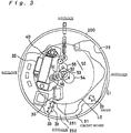
- Fig. 3 is an explanatory view showing the layout, as viewed from above, of a stepping motor, a watch wheel train, a circuit board, etc. in the electronic watch with hands according to the embodiment of the present invention.
- Fig. 4 is a vertical sectional view showing the positional relationship between the circuit board and a oscillating weight in the electronic watch with hands according to the embodiment of the present invention.
- Fig. 5 is an explanatory view showing the positional relationship, as viewed from above, between parts of a mechanism for adjusting the indicated time of day in the electronic watch with hands according to the embodiment of the present invention.
- Fig. 6 is a vertical sectional view showing the positional relationship between the parts of the mechanism for adjusting the indicated time of day in the electronic watch with hands according to the embodiment of the present invention.
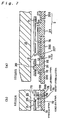
- Fig. 7(a) is a vertical sectional view of a mechanism section for adjusting the indicated time of day in the electronic watch with hands according to the embodiment of the present invention, the mechanism section being cut in the radial section, and Fig. 7(b) is a side sectional view of the mechanism section.
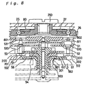
- Fig. 8 is a vertical sectional view of the watch wheel train and thereabout assembled in the electronic watch with hands according to the embodiment of the present invention.
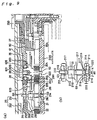
- Fig. 9(A) is a vertical sectional view of a dynamo wheel train and thereabout assembled in the electronic watch with hands according to the embodiment of the present invention, and Fig. 9(B) is an enlarged view of a bearing portion supporting a rotational shaft of a dynamo rotor.
- Fig. 10 is a vertical sectional view of the small-sized dynamo and thereabout assembled in the electronic watch with hands according to the embodiment of the present invention.
- Fig. 11 is an explanatory view showing a conventional bearing structure.
-
-
- 1
- electronic watch with hands
- 2
- base
- 20
- small-sized dynamo
- 21
- dynamo rotor
- 22
- dynamo stator
- 23
- dynamo coil
- 24
- magnetic core
- 25
- oscillating weight
- 26
- oscillating weight support
- 27, 28
- ball bearings
- 30
- secondary power supply
- 31
- circuit board
- 40
- stepping motor
- 41
- motor coil
- 42
- motor rotor
- 43
- motor stator
- 50
- watch wheel train
- 56
- hour wheel
- 60
- dynamo wheel train
- 62
- dynamo rotor transmitting wheel
- 74
- wheel train setting lever
- 75
- reset lever
- 80
- wheel train bridge
- 200
- main plate
- 205
- through-hole of circuit support seat (circuit part installation hole)
- 207
- recess of circuit support seat (circuit part installation hole)
- 211
- rotational shaft of dynamo rotor
- 212, 214
- hole jewels
- 213, 215
- caps
- 211
- rotational shaft
- 217
- conical portion
- 218
- looseness eliminating step
- 219
- fitting depth determining boss
- 222
- gap between end surface of hole jewel and cap
- 251
- thinner wall portion of oscillating weight
- 252
- thicker wall portion of oscillating weight
- 303
- conical plate spring
- 280
- frame
- 281
- ball
- 282
- frame piece
- 283
- retainer piece
- 311
- circuit support seat
- 620
- rotational shaft of dynamo rotor transmitting wheel
- G1
- lubricant holding gap
- G2
- gap between hour wheel and dial
- G3
- lubricant holding annular slot
- An embodiment of the present invention will be described hereunder with reference to the drawings.
- Fig. 1 is a schematic exploded view showing the general construction of an electronic watch. A basic structure of the electronic watch of this embodiment is similar to that of a conventional electronic watch. Therefore, components having functions common to the electronic watch of this embodiment and the conventional electronic watch are denoted by the same reference numerals in the following description.
- In Fig. 1, an
electronic watch 1 with hands of this embodiment is an analog quartz wrist watch of type indicating the time of day by the hands. A steppingmotor 40 is driven in accordance with a signal output from acrystal oscillator 32 mounted on acircuit board 31. The steppingmotor 40 comprises amotor rotor 42 having a permanent magnet magnetized into two poles, amotor stator 43 having a cylindricalrotor installation hole 430 in which themotor rotor 42 is disposed, and a coil block formed by winding a coil 41 over amagnetic core 44. A watch wheel train 50 comprised of afifth wheel 51, asecond wheel 52, athird wheel 53, acenter wheel 54, aminute wheel 55 and ahour wheel 56 is operatively connected to themotor rotor 42 through respective pinions. Asecond hand 161 is fixed to the distal end of a shaft of thesecond wheel 52 of the watch wheel train. Aminute hand 162 is fixed to the distal end of a cylindrical shaft of thecenter wheel 54. Anhour hand 163 is fixed to the distal end of a cylindrical shaft of thehour wheel 56. Here, a speed reducing ratio achieved through the gearing from themotor rotor 42 to thesecond wheel 52 is set to 1/30. Thesecond hand 161 is constructed such that it is intermittently rotated in steps of 6° whenever themotor rotor 42 is intermittently rotated in steps of 180° for each second. - A
power supply section 10 for driving the steppingmotor 40 is primarily made up of a small-sized dynamo 20 and a secondary power supply 30 (capacitor). In order to generate power upon movement of the user's wrist over which theelectronic watch 1 with hands is fitted, the small-sized dynamo 20 comprises an eccentricoscillating weight 25 rotatable in response to the wrist movement, adynamo rotor 21 rotated by receiving kinetic energy from theoscillating weight 25, adynamo stator 22 disposed in surrounding relation to thedynamo rotor 21, and adynamo coil 23 wound over amagnetic core 24 making up a magnetic circuit in cooperation with thedynamo stator 22 and thedynamo rotor 21. Theoscillating weight 25 and thedynamo rotor 21 are operatively interconnected through adynamo wheel train 60 for transmitting rotation of theoscillating weight 25 while speeding up the rotation. Thedynamo wheel train 60 is made up of aoscillating weight wheel 61 formed integrally with theoscillating weight 25, and a dynamorotor transmitting wheel 62 having a pinion held in mesh with theoscillating weight wheel 61. Thedynamo rotor 21 has a permanent magnet magnetized to have N and S poles which are rotated when the rotation of theoscillating weight 25 is transmitted to thedynamo rotor 21. Accordingly, induced electromotive force can be taken out of thedynamo coil 23 and charged into thesecondary power supply 30. - The
oscillating weight 25 has, though described later in more detail, a oscillatingweight fixing screw 250 attached to its rotating central portion. Theoscillating weight 25 is formed such that its inner peripheral portion around the oscillating weight fixing screw 250 (rotating central portion) provides athinner wall portion 251 as a light oscillating weight, and its outer peripheral portion provides athicker wall portion 252 as a heavy oscillating weight stretching radially outward from the light oscillating weight. As a result, in spite of a reduction in thickness of theoscillating weight 25, weight unbalance of theoscillating weight 25 in the angular direction remains large. - The layout of various parts for developing a power generating function and a hand driving function will be described with reference to Figs. 2 and 3. Fig. 2 is an explanatory view showing the layout, as viewed from above, of the small-sized dynamo and other parts in the electronic watch with hands of this embodiment, and Fig. 3 is an explanatory view showing the layout, as viewed from above, of the stepping motor, the watch wheel train, the circuit board, etc. in the electronic watch with hands. Fig. 2 is a plan view showing a state where principal parts are mounted on a main plate constituting a base in the electronic watch with hands of this embodiment.
- Referring to Fig. 2, a central portion of a
main plate 200 serves as the center of rotation of theoscillating weight 25 and the hands. A dial of the watch is disposed on the rear side of themain plate 200, and the time of day is indicated on the drawing at corresponding angular positions of themain plate 200. - In Fig. 2, a rotating area of the
oscillating weight 25 is indicated by a two-dot-chain line L1 positioned slightly inward of an outer peripheral edge of themain plate 200. Inside the two-dot-chain line L1, there is indicated another two-dot-chain line L2 representing a boundary between a rotating area of thethinner wall portion 251 of theoscillating weight 25 and a rotating area of thethicker wall portion 252 thereof. - In this embodiment, the small-
sized dynamo 20 is arranged in the rotating area of theoscillating weight 25 so as to extend over both the rotating area of thethinner wall portion 251 and the rotating area of thethicker wall portion 252. The dynamorotor transmitting wheel 62 is meshed with apinion 210 of themotor rotor 21, and theoscillating weight wheel 61 fixed to theoscillating weight 25 is meshed with apinion 620 of the dynamorotor transmitting wheel 62. Here, the dynamorotor transmitting wheel 22, themotor rotor 21, etc., as well as theoscillating weight wheel 61, which are parts of thedynamo wheel train 60 having relatively large height, are all arranged in the rotating area of thethinner wall portion 251. - The
oscillating weight 25 and thedynamo wheel train 60 are both supported by aoscillating weight support 26 in the form of a flat plate. Theoscillating weight support 26 is also entirely disposed in the rotating area of thethinner wall portion 251. Further, theoscillating weight support 26 is fixed to themain plate 200 by threescrews thinner wall portion 251. - As a result of thus effectively utilizing a space in the rotating area of the
thinner wall portion 251, the thickness of theelectronic watch 1 with hands can be reduced. In addition, theelectronic watch 1 can be easily disassembled because theoscillating weight support 26 can be removed in its entirety if theoscillating weight 25 is removed. - Within the rotating area of the
thinner wall portion 251, as shown in Fig. 3, there is further disposed the watch wheel train 50 comprised of thefifth wheel 51, thesecond wheel 52, thethird wheel 53, thecenter wheel 54, theminute wheel 55 and thehour wheel 56 which have each a relatively large height. - Accordingly, even with the structure that the
thicker wall portion 252 is provided as the heavy oscillating weight in the outer peripheral portion of theoscillating weight 25 for the purpose of increasing weight unbalance of theoscillating weight 25 in the angular direction, no trouble occurs in arrangement of the train wheels. Further, an area of thethinner wall portion 251 can be enlarged corresponding to increased weight unbalance of theoscillating weight 25, thereby securing a larger space for arrangement of the other parts. Thus, the above structure is advantageous in achieving a reduction in thickness of theelectronic watch 1 with hands. - On the contrary, relatively thin members are arranged in the rotating area of the
thicker wall portion 252 of theoscillating weight 25. First, since thecircuit board 31 formed of a flexible board, on whichdiodes 33, etc. making up a driving circuit are mounted, is relatively thin, it is arranged in the rotating area of thethicker wall portion 252 of theoscillating weight 25 by utilizing a gap between thethicker wall portion 252 of theoscillating weight 25 and themain plate 200. - As shown in Figs. 3 and 4, however, since a
crystal oscillator 32 and anIC driving capacitor 35 require a relatively large dimension for installation thereof, these parts are arranged laterally of the circuit board (in the rotating area of thethinner wall portion 251 of the oscillating weight 25), while they are connected to thecircuit board 31 through wires. - Aside from those parts, surface-mounted parts such as the
diodes 33 are mounted on thecircuit board 31, and thecircuit board 31 is arranged such that thediodes 33, etc. face themain plate 200. In other words, thediodes 33, etc. are disposed in respective through-holes 206 formed in themain plate 200. Acircuit support seat 311 made of insulating material is fitted to inner peripheral surfaces of the through-holes 206 in themain plate 200, and thediodes 33, etc. are positioned in respective through-holes 205 (circuit part installation holes) formed in thecircuit support seat 311. - Thus, of the
main plate 200 and thecircuit support seat 311 jointly constituting thebase 2, thecircuit support seat 311 is utilized to receive thediodes 33, etc. in the through-holes 205. Therefore, more than half of electronic parts mounted on thecircuit board 31 and making up the driving circuit can be arranged in the rotating area of thethicker wall portion 252 where the gap size between the oscillating weight and main plate is small. In addition, since those electronic parts are surrounded by the insulatingcircuit support seat 311 fitted to the inner peripheral surfaces of the through-holes 206 in themain plate 200, a trouble such as a short-circuit is surely prevented. - Fig. 5 is an explanatory view showing the positional relationship, as viewed from above, between parts of a mechanism for adjusting the indicated time of day in the electronic watch with hands according to the embodiment.
- As shown in Fig. 5, the
electronic watch 1 with hands also includes a mechanism for adjusting the second hand, etc. by the user operating a crown 7 (external operating member) from the outside. This mechanism is constructed as follows. A settinglever 71 engages with a shaft coupled to thecrown 7, and the position of the settinglever 71 is restricted by ayoke holder 76. Ayoke 72 engages in a groove of a slidingpinion 73 which is coupled to the shaft of thecrown 7. Therefore, when thecrown 7 is pulled outward one step, the settinglever 71 is rotated in the direction of arrow A. Here, a dowel formed on the settinglever 71 engages in a cam slot of a trainwheel setting lever 74. Accordingly, in response to thecrown 7 being pulled outward, the trainwheel setting lever 74 is rotated in the direction of arrow B to engage with thefifth wheel 51, thereby stopping motion of thesecond hand 161. By turning thecrown 7 about its axis in such a condition, theminute wheel 55 and so forth can be rotated through asetting wheel 79. The provision of that mechanism enables the hands to be adjusted for the correct time of day while thesecond hand 161 is kept stopped, so that the indicated time of day can be adjusted even in a unit of second. - Further, a
reset lever 75 is also connected to the settinglever 71 through a cam mechanism. When thecrown 7 is pulled outward one step, thereset lever 75 is rotated in the direction of arrow C.A contact portion 315 extending from thecircuit board 31 is positioned on the side toward which thereset lever 75 is rotated. In interlock with the pulling-out of thecrown 7 in one step, therefore, thecontact portion 315 is pushed by thereset lever 75 to actuate a switch. In this state, output of a driving signal to the steppingmotor 40 from the driving circuit (not shown) constructed on thecircuit board 31 is stopped and themotor rotor 42 also stops its rotation. - Here, as will be seen from Fig. 6, the
reset lever 75 and the trainwheel setting lever 74 are each formed of a relatively thin plate member. Of these two levers, the trainwheel setting lever 74 acts directly on thefifth gear 51 and therefore it is required to locate in a central portion of themain plate 200. Thus, the trainwheel setting lever 74 is disposed in the rotating area of thethinner wall portion 251 of the oscillating weight 25 (i.e., between the rotating level of thethinner wall portion 251 of theoscillating weight 25 and the main plate 200). - On the other hand, the
reset lever 75 is formed of a thin metallic plate and is just required to position in such a manner as able to contact part of thecircuit board 31. Accordingly, thereset lever 75 is arranged in the rotating area of thethicker wall portion 252 of the oscillating weight 25 (i.e., between the rotating level of thethicker wall portion 252 of theoscillating weight 25 and the main plate 200). - The
reset lever 75 formed of a metallic plate also constitutes part of the circuit section. Further, thereset lever 75 is arranged close to themain plate 200 as with thediodes 33 on thecircuit board 31 which have been described above in connection with Fig. 4. Specifically, in this embodiment, thereset lever 75 is arranged in a recess 207 (circuit part installation hole) of the insulatingcircuit support seat 311 which is fitted to a through-hole 208 of themain plate 200. - Thus, in this embodiment, of the
main plate 200 and thecircuit support seat 311 jointly constituting thebase 2, thecircuit support seat 311 is utilized to receive thereset lever 75 in the circuit part installation hole defined by therecess 207. Therefore, thereset lever 75 can be arranged in the rotating area of thethicker wall portion 252 where the gap size between the oscillating weight and main plate is small. In addition, since thereset lever 75 is surrounded by the insulatingcircuit support seat 311, a trouble such as a short-circuit is surely prevented. - Further, changeover members such as the setting
lever 71 and theyoke 72 are firmly held down by theyoke holder 76 in the rotating area of thethicker wall portion 252 of the oscillating weight 25 (i.e., between the rotating level of thethicker wall portion 252 of theoscillating weight 25 and the main plate 200). - As described above, the thickness of the
electronic watch 1 with hands of this embodiment is reduced by sufficiently utilizing not only the rotating area of thethinner wall portion 251 of theoscillating weight 25, but also the narrow gap between thethicker wall portion 252 of theoscillating weight 25 and themain plate 200. - Additionally, as will be seen from Fig. 7(a), the
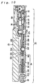
circuit board 31 is positioned by fitting ahole 310 formed in thecircuit board 31 over a correspondingprojection 312 on thecircuit support seat 311, and it is simultaneously firmly held down by acircuit retainer plate 310. Also, as will be seen from Fig. 7(b), a portion of the end of thecircuit board 31 is laterally extended to provide acontact 315. When acontact counterpart 755 formed by bending a tip of thereset lever 75 is moved laterally from a base position (state where thecrown 7 is pushed in / 0th step) upon the pulling-out of crown 7 (i.e., when thecrown 7 is pulled out one step), thecontact counterpart 755 of thereset lever 75 is brought into contact with thecontact 315 of thecircuit board 31. Conversely, when thecrown 7 is pushed in from the pulled-out state, thecontact 315 and thecontact counterpart 755 are separated from each other, whereupon the driving signal from the driving circuit is allowed to be output to the steppingmotor 40. This causes themotor rotor 42 to start rotation again. Further, the pushing-in of thecrown 7 makes the trainwheel setting lever 74 separate from thefifth wheel 51, allowing thesecond hand 161 to resume rotation. - Fig. 8 is a vertical sectional view of the watch wheel train and thereabout assembled in the electronic watch with hands of this embodiment, Fig. 9(A) is a vertical sectional view of the dynamo wheel train and thereabout assembled in the electronic watch with hands, Fig. 9(B) is an enlarged view of a bearing portion supporting the rotational shaft of the dynamo rotor, and Fig. 10 is a vertical sectional view of the small-sized dynamo and thereabout assembled in the electronic watch with hands.
- As shown in Fig. 8, the
oscillating weight 25 is fixed in place by the oscillatingweight fixing screw 250 through aball bearing 27 which is in turn fixed to theoscillating weight support 26. Awheel train bridge 80 is disposed between theball bearing 27 and themain plate 200. One axial ends ofrotational shafts third wheel 53 and thefifth wheel 51 are supported throughhole jewels 531, 511 inholes wheel train bridge 80, respectively. The other axial ends of therotational shafts third wheel 53 and thefifth wheel 51 are supported throughhole jewels holes main plate 200, respectively. - An outer peripheral portion of the
hour wheel 56 is extended outward to a position overlapping thehole jewels third wheel 53 and thefifth wheel 51. Thehour wheel 56 has opposite end surfaces shaped such that one of the end surfaces on which the hour hand locates is cut to hollow slightly in its innerperipheral portion 561, and the other end surface is cut to hollow slightly in its outerperipheral portion 562. This structure surely defines a gap G1 between thehour wheel 56 and thehole jewels - A
dial 3 of the watch is layered on themain plate 200.Holes 301 are formed in thedial 3 so that the rotational shaft of each train wheel can penetrate thedial 3 through the corresponding hole. - The
dial 3 is arranged to extend along one of the end surfaces of thehour wheel 56 on which the hour hand locates. Because the innerperipheral portion 561 of thehour wheel 56 is cut to hollow slightly in the one end surface on which the hour hand locates, aconical plate spring 303 can be interposed between the innerperipheral portion 561 of thehour wheel 56 and thedial 3. Thus, by fitting one piece ofconical plate spring 303 over thehour wheel 56 to position between thehour wheel 56 and thedial 3, it is possible to keep thehour wheel 56 and thedial 3 away from each other by a distance represented by a gap G2 in the innerperipheral portion 561 of thehour wheel 56. Accordingly, even if drilling thehole 301 in thedial 3 cause burrs (warped edges) along the hole circumference projecting toward a gear portion of thehour wheel 56, the burrs would not impede the rotation of thehour wheel 56. Additionally, since the gap G2 is surely maintained by the presence of theconical plate spring 303 and the hollowed innerperipheral portion 561 of thehour wheel 56, the spacing between thehour wheel 56 and thedial 3 can be set to a necessary minimum size. This also contributes to reducing the thickness of theelectronic watch 1 with hands. - In a position offset from the center of the
main plate 200, as shown in Fig. 9(A), the dynamorotor transmitting wheel 62, which is one of the wheels making up thedynamo wheel train 60 and has thepinion 621 held in mesh with theoscillating weight wheel 61, is supported between theoscillating weight support 26 and themain plate 200. Therotational shaft 620 of the dynamorotor transmitting wheel 62 is supported at its one axial end by aball bearing 28 which is held in a hole 263 formed in theoscillating weight support 26. - The
ball bearing 28 comprises a plurality ofballs 281 arranged around therotational shaft 620 and a ring-shapedframe 280 for accommodating theballs 281 therein. Theframe 280 comprises a ring-shapedframe piece 282 for holding theballs 281 from two directions, and aretainer piece 283 positioned adjacent theframe piece 282 for cooperating with it to prevent theballs 281 from slipping off. On the other hand, therotational shaft 620 of the dynamorotor transmitting wheel 62 has a steppedportion 626 formed in opposite relation to theretainer piece 283. Here, theballs 281 are partly projecting out of a gap between an inner peripheral edge of the retainer piece 283 (inner peripheral edge of one of both end surfaces of theframe 280 on the side where the steppedportion 626 locates) and therotational shaft 620, so that the balls come into abutment against the steppedportion 626. - In the bearing structure thus constructed, since the
balls 281 are held in abutment against the circumferential surface of therotational shaft 620, a lateral inclination of therotational shaft 620 is completely prevented. Also, therotational shaft 620 has a play in the vertical direction. Of the up and down directions, however, a displacement of therotational shaft 620 in the direction of arrow D is also completely prevented, because the steppedportion 626 abuts against theballs 281 when therotational shaft 620 tends to shift over a predetermined distance in the direction of arrow D. Thus, when the dynamorotor transmitting wheel 62 is rotated upon the motion of theoscillating weight 25, the steppedportion 626 and theballs 28 contact with each other through not sliding friction but rolling friction, and hence the load loss of the wheel train can be kept small. Accordingly, in theelectronic watch 1 with hands of this embodiment, it is possible to determine fit looseness of the dynamorotor transmitting wheel 62 with a simple structure and reduce the thickness of the electronic watch. Moreover, since the dynamorotor transmitting wheel 62, one of the train wheels which is most easily subject to lateral pressure, undergoes relatively small friction in its bearing portion, the efficiency of power generation is increased. - Note that since a
hole jewel 622 is fitted over the opposite axis end of therotational shaft 620 of the dynamorotor transmitting wheel 62 and is held in ahole 204 formed in themain plate 200, fit looseness of the dynamorotor transmitting wheel 62 in the direction toward the main plate is determined by thehole jewel 622. - Laterally of a
gear portion 623 of the dynamorotor transmitting wheel 62, there is positioned awall 804 formed at the end of thewheel train bridge 80. More specifically, in this embodiment, a portion of thewheel train bridge 80 is formed into a wall which locates between thewatch wheel train 50 and thedynamo wheel train 60 and serves to prevent scattering of a lubricant. Even with the dynamorotor transmitting wheel 62 rotating at a high speed, therefore, the lubricant applied to therotational shaft 620 and thegear portion 623 is prevented from scattering to thethird wheel 53, etc. This means that abnormal motion in driving the hands, such as stop or delay of thethird wheel 53, etc., due to viscosity of the lubricant is hard to occur and power consumed to compensate for the abnormal motion in driving the hands can be reduced. In addition, since scattering of the lubricant is prevented by utilizing a portion of thetrain wheel bridge 80 which has been conventionally used in existing electronic watches, the thickness of theelectronic watch 1 with hands can be reduced. Further, because no lubricant scatters to the surroundings, the parts can be arranged with narrower gaps between them. Correspondingly, a larger space for installation of the parts can be ensured, which also contributes to reducing the thickness of theelectronic watch 1 with hands. - Laterally of the dynamo
rotor transmitting wheel 62, thedynamo rotor 21 having thepinion 210 held in mesh with thegear portion 623 of the dynamorotor transmitting wheel 62 is supported between theoscillating weight support 26 and themain plate 200. - A
hole jewel 212 is fitted over one axial end of arotational shaft 211 of thedynamo rotor 21. Thehole jewel 212 is held in ahole 266 formed in theoscillating weight support 26 while it is fitted into a ring-shapedcap 213. Also, anotherhole jewel 214 is fitted over the other axial end of therotational shaft 211 of thedynamo rotor 21. Thehole jewel 214 is held in ahole 205 formed in themain plate 200 while it is fitted into a ring-shapedcap 215. - In this embodiment, the bearing portions using the
hole jewels caps hole jewel 214 and thecap 215 with reference to Fig. 9(B). - In the illustrated bearing portion, the
cap 215 not only covers the lateral side of thehole jewel 214, but also partly covers oneend surface 216 of thehole jewel 214, which faces thedynamo rotor 21, from the outer side. Accordingly, an annular slot G3 for holding a lubricant between an inner peripheral surface of thecap 215 and an outer circumferential surface of therotational shaft 211 is defined in a position corresponding to an inner portion of theend surface 216 of thehole jewel 214. The annular slot G3 has an opening width in the range of, e.g., about 40 µm to about 100 µm. Further, the annular slot G3 has a relatively large depth almost equal to the thickness of thecap 215. Even with thedynamo rotor 21 rotating at a high speed, therefore, the lubricant is surely prevented from spilling out of the annular slot G3 and scattering to the surroundings. As a result, the spacing between the adjacent parts can be narrowed and the thickness of theelectronic watch 1 with hands can be reduced. - Moreover, the lubricant tends to scatter most easily from the bearing portion of the
dynamo rotor 21 which is rotated at a maximum speed among the train wheels. In this embodiment, however, since therotational shaft 211 of thedynamo rotor 21 is supported by the above-stated bearing structure, scattering of the lubricant can be effectively prevented. - Here, the
cap 215 and thehole jewel 214 are formed as separate parts and assembled such that thehole jewel 214 is fitted into thecap 215. To prevent the lubricant from permeating into the space between thehole jewel 214 and thecap 215 and spreading further from there, this embodiment is practiced by immersing an assembly of thehole jewel 214 and thecap 215 fitted to each other in a treatment solution so that all the surfaces of thehole jewel 214 and thecap 215 are subject to surface treatment for preventing spread of the lubricant. Specifically, a fluorine-base coating is dissolved in a fluorine-base solvent to prepare a treatment solution, and the assembly of thehole jewel 214 and thecap 215 fitted to each other is immersed in the treatment solution. After the immersion, the assembly is dried to remove the solvent. As a result, a thin layer of the fluorine-base coating is formed all over the surfaces of thehole jewel 214 and thecap 215. Because the thin layer of the fluorine-base coating formed by the surface treatment serves to repel the lubricant, the lubricant is prevented from permeating into the space between thehole jewel 214 and thecap 215 and spreading further from there. - For the purpose of effectively conducting the above-mentioned surface treatment, in this embodiment, a
gap 222 of predetermined size is positively maintained between thecap 215 and theend surface 216 of thehole jewel 214. The presence of thegap 222 enables the treatment solution to enter the space between thecap 215 and thehole jewel 214 so sufficiently that the surface treatment for preventing spread of a lubricant can be surely applied to all over the surfaces of thecap 215 and thehole jewel 214. Therefore, the lubricant maintained in the lubricant holding annular slot G3 will not spread through between thecap 215 and thehole jewel 214. For ensuring thegap 222, in this embodiment,bosses 219 are projected on thecap 215 to determine a depth of fitting resulted when thehole jewel 214 is fitted into thecap 215. Thus, by simply fitting thehole jewel 214 into thecap 215, it is possible to surely provide thegap 222 corresponding to the height of thebosses 219. The size of thegap 222 is about 10 µm, for example, taking into account the coating layer of about 1 µm formed by the surface treatment and the accuracy of machining. - In this embodiment, the
rotational shaft 211 has aconical portion 217 formed in its outer circumferential surface near each of both the axial ends supported by thehole jewels rotational shaft 211 increases gradually in theconical portion 217 toward the portion where the lubricant holding annular slot G3 is defined. Therefore, even if the lubricant spills and adheres onto therotational shaft 211, the lubricant adhering onto theconical portion 217 is forced to move toward a larger diameter end of the conical portion 217 (i.e., toward the lubricant holding annular slot G3) under an influence of centrifugal force when therotational shaft 211 is rotated. As a result, the spilled lubricant is returned to the lubricant holding annular slot G3 and is surely prevented from scattering to the surroundings. - Furthermore, steps 218 (looseness eliminating steps) projecting in opposite relation to the
hole jewels rotational shaft 211. Therefore, if therotational shaft 211 is shifted in the axial direction, thestep 218 comes into abutment against the inner end surface of each of thehole jewels rotational shaft 211. Here, the position at which thestep 218 is formed on the outer circumferential surface of therotational shaft 211, and the depth of the annular slot G3 (the thickness of thecap 215 defining the annular slot G3) are set so that thestep 218 is always located within the lubricant holding annular slot G3 even when therotational shaft 211 is axially shifted in either direction. With this construction, even if the lubricant is forced to scatter out of the annular slot G3, the outgoing lubricant is blocked by thestep 218 of therotational shaft 211 and hence scattering of the lubricant is more surely prevented. In this embodiment, for example, the depth of the annular slot G3 is set to about 100 µm or above. Note that since the depth of the annular slot G3 as small as possible is advantageous in reducing the thickness of the electronic watch with hands, the depth of the annular slot G3 is set to a necessary minimum value within the range enough to prevent scattering of the lubricant. - Further, a
lubricant injection recess 220 is formed in the outer end surface of each of thehole jewels recess 220, the injected lubricant permeates into openings of thehole jewel 214 and then accumulates in the lubricant holding annular slot G3. Here, therecess 220 has an outer diameter D larger than an outer diameter d of the lubricant holding annular slot G3, and also has an inner volume larger than that of the annular slot G3. This ensures that the amounts of the lubricant held by the annular slot G3 and thelubricant injection recess 220, respectively, are balanced. - As shown in Fig. 10, the
dynamo rotor 21 is located in surrounded relation by thedynamo stator 22. Thedynamo stator 22 is connected to themagnetic core 24 of the small-sized dynamo 20. Themagnetic core 24 comprises a lowermagnetic core 241 positioned on themain plate 200 and an uppermagnetic core 242 placed over the lowermagnetic core 241. Of these two layered magnetic cores, the lowermagnetic core 241 is connected to thedynamo stator 22 through acore connecting screw 246 and ascrew seat 247. - In the connecting portion between the
magnetic core 24 and thedynamo stator 22, the lowermagnetic core 241 is extended horizontally beyond the end of the outermagnetic core 242 toward thedynamo stator 22. The end of thedynamo stator 22 is bent to provide ajoint end 220 which is positioned to lie over anextended portion 240 of the lowermagnetic core 241. Also, thejoint end 220 is machined to have athinner wall portion 221 in an area where it is fastened by thecore connecting screw 246. Thus, the thickness of the connecting portion between themagnetic core 24 and thedynamo stator 22 can be kept small because it is given by the sum of the thickness of the lowermagnetic core 241 and thethinner wall portion 221 of thejoint end 220 of thedynamo stator 22. - As described above, the connecting portion between the
dynamo stator 22 and themagnetic core 24 has such a sectional structure that themain plate 200, themagnetic core 24 and thedynamo stator 24 are layered one above another in the order named. Also, in the sectional structure, the joint end 220 (joint portion) of thedynamo stator 22 has anupper surface 222 and alower surface 223 which are both positioned between anupper surface 224 and alower surface 225 of thedynamo stator 22 arranged in surrounding relation to thedynamo rotor 211. Further, theupper surface 222 of thejoint end 220 is positioned at a lower level than anupper surface 211 of the magnet of thedynamo rotor 21. Therefore, theelectronic watch 1 with hands according to this embodiment can have a reduced thickness. - Additionally, the
dynamo stator 22 is machined into thethinner wall portion 221 only in the joint portion thereof with themagnetic core 24, and the other portion of thedynamo stator 22 still remains as a thicker wall portion. Therefore, theextended portion 240 of the lowermagnetic core 241 and the thicker wall portion of thedynamo stator 22 can be brought into contact with each other in an area around the joint portion of thedynamo stator 22. That structure prevents a reduction in intensity of the allowable magnetic flux in the area around the joint portion of thedynamo stator 22, and keeps the magnetic flux passing through the magnetic circuit of the small-sized dynamo 20 from leaking out from there. Also, that structure eliminates a need of partly reducing the thickness of themain plate 200 with intent to reduce the thickness of the joint portion of thedynamo stator 22. As a result, the strength of themain plate 200 can be kept high. - In the above embodiment, the invention relating to a ball bearing for a rotational shaft of a gear has been explained in connection with the bearing structure for the dynamo
rotor transmitting wheel 62 of thedynamo wheel train 60. However, the bearing structure may also be applied to the rotational shaft of any other gear or the like. While the bearing structure of the above embodiment has been applied to only one axial end of therotational shaft 620 of the dynamorotor transmitting wheel 62, it may also be applied to both the axial ends of therotational shaft 620. - In the above embodiment, the bearing portion for the rotational shaft has been explained as being made up of the
hole jewel 214 and thecap 215 separate from each other. But thehole jewel 214 and thecap 215 may be constructed respectively as a hole jewel portion and a cap portion of one unitary component. Alternatively, thehole jewel 214 and thecap 215 may be constructed integrally with thebase 2 to serve as a hole jewel portion and a cap portion, respectively. This integration of thehole jewel 214 and thecap 215 into one unitary component contributes to reducing the production cost of the electronic watch with hands. - As described above, the electronic watch according to the first aspect of the present invention is featured in using a bearing portion comprised of a hole jewel portion supporting an axial end of a rotational shaft, and a ring-shaped cap portion covering one end surface of the hole jewel portion from the outer side to define a lubricant holding annular slot between the cap portion and an outer circumferential surface of the rotational shaft. With the present invention, therefore, a lubricant applied to between the rotational shaft and the hole jewel portion is held in the lubricant holding annular slot and is prevented from scattering to the surroundings even under rotation of the rotational shaft. Consequently, gaps between adjacent parts can be narrowed and a thinner electronic watch can be provided.
- In the electronic watch according to the second aspect of the present invention, since the position of the rotational shaft is restricted in two directions by balls themselves of a ball bearing, the rotational shaft can be supported through a rolling bearing in any of the two directions. This results in small friction resistance exerted on the rotational shaft during its rotation. Additionally, such a bearing structure is achieved just by partly improving a ball bearing structure, and hence has a size remaining small. As a result, a thinner electronic watch can be provided.
- The electronic watch according to the third aspect of the present invention is featured in that a oscillating weight is constructed of a thinner wall portion and a thicker wall portion to increase weight unbalance of the oscillating weight, and necessary members are arranged in an optimum state separately in respective rotating areas of the thinner wall portion and the thicker wall portion of the oscillating weight. With the present invention, therefore, a narrow gap defined in the rotating area of the thicker wall portion of the oscillating weight can also be utilized effectively and hence a thinner electronic watch can be provided.
Claims (9)
- An electronic watch having a base on which are mounted a dynamo including a dynamo wheel train for transmitting external force to a dynamo rotor, a secondary power supply for storing electric energy generated by said dynamo, a circuit section including a driving circuit supplied with power from said secondary power supply, a stepping motor driven by said driving circuit, and a watch wheel train for transmitting torque from said stepping motor to a time indicating member, wherein:said electronic watch includes an oscillating weight for transmitting external force to said dynamo rotor through said dynamo wheel train, said oscillating weight comprising a rotating central portion supported by said base, a thinner wall portion formed around said rotating central portion, and a thicker wall portion formed around said thinner wall portion,said watch wheel train and said dynamo wheel train are arranged on said base in a rotating area of said thinner wall portion, anda part of said circuit section which is positioned in a rotating area of said thicker wall portion is arranged in a circuit part installation hole defined in said base in the form of a recess or a though-hole,
- An electronic watch according to claim 1, wherein the part of said circuit section which is arranged in said circuit part installation holes in the rotating area of said thicker wall portion is an electronic part making up said driving circuit.
- An electronic watch according to claim 1, wherein a wheel train setting lever operatively connected to a setting lever is arranged on said base in the rotating area of said thinner wall portion, said wheel train setting lever stopping motion of said watch wheel train when said setting lever is operated upon external operation applied to an external operating member, andthe part of said circuit section which is arranged in said circuit part installation hole in the rotating area of said thicker wall portion is a reset lever operatively connected to said setting lever and serving as a switch for temporarily stopping and restarting rotation of said stepping motor.
- An electronic watch according to any one of claims 1 to 3, wherein said base comprises a metallic main plate and a circuit support seat made of insulating material, and said circuit part installation hole is formed in said circuit support seat.
- An electronic watch according to any one of claims 1 to 3, wherein a screw fastening portion of an oscillating weight and said dynamo wheel train through respective bearings is disposed on said base in the rotating area of said thinner wall portion.
- An electronic watch according to claim 5, wherein said oscillating weight support is entirely disposed on said base in the rotating area of said thinner wall portion.
- An electronic watch according to claim 1, wherein said watch wheel train includes an hour wheel coupled to a hour hand, andsaid hour wheel has opposite end surfaces machined such that one end surface on the side where said hour hand locates is cut to hollow slightly in an inner peripheral portion thereof, and the other end surface on the opposite side is cut to hollow slightly in an outer peripheral portion thereof.
- An electronic watch according to claim 1, wherein a wall for preventing scattering of a lubricant is formed between said watch wheel train and said dynamo wheel train by a portion of a wheel train bridge supporting said watch wheel train.
- An electronic watch according to claim 1, wherein a connecting portion between said dynamo stator and a dynamo magnetic core of said dynamo has a sectional structure that a main plate, said dynamo magnetic core and said dynamo stator are layered one above another in the order named, that a joint portion of said dynamo stator with said dynamo magnetic core has upper and lower surfaces which are both positioned between upper and lower surfaces of said dynamo stator arranged in surrounding relation to said dynamo rotor, and that the upper surface of said joint portion is positioned at a lower level than an upper surface of a magnet of said dynamo rotor.
Applications Claiming Priority (7)
| Application Number | Priority Date | Filing Date | Title |
|---|---|---|---|
| JP30315095 | 1995-11-21 | ||
| JP30315095 | 1995-11-21 | ||
| JP30314995 | 1995-11-21 | ||
| JP303149/95 | 1995-11-21 | ||
| JP303150/95 | 1995-11-21 | ||
| JP30314995 | 1995-11-21 | ||
| EP96938523A EP0805380B1 (en) | 1995-11-21 | 1996-11-21 | Electronic timepiece |
Related Parent Applications (1)
| Application Number | Title | Priority Date | Filing Date |
|---|---|---|---|
| EP96938523A Division EP0805380B1 (en) | 1995-11-21 | 1996-11-21 | Electronic timepiece |
Publications (3)
| Publication Number | Publication Date |
|---|---|
| EP0908797A2 true EP0908797A2 (en) | 1999-04-14 |
| EP0908797A3 EP0908797A3 (en) | 2000-12-13 |
| EP0908797B1 EP0908797B1 (en) | 2004-09-15 |
Family
ID=26563416
Family Applications (3)
| Application Number | Title | Priority Date | Filing Date |
|---|---|---|---|
| EP98204248A Expired - Lifetime EP0908797B1 (en) | 1995-11-21 | 1996-11-21 | Electronic watch |
| EP98204249A Expired - Lifetime EP0908798B1 (en) | 1995-11-21 | 1996-11-21 | Electronic watch |
| EP96938523A Expired - Lifetime EP0805380B1 (en) | 1995-11-21 | 1996-11-21 | Electronic timepiece |
Family Applications After (2)
| Application Number | Title | Priority Date | Filing Date |
|---|---|---|---|
| EP98204249A Expired - Lifetime EP0908798B1 (en) | 1995-11-21 | 1996-11-21 | Electronic watch |
| EP96938523A Expired - Lifetime EP0805380B1 (en) | 1995-11-21 | 1996-11-21 | Electronic timepiece |
Country Status (7)
| Country | Link |
|---|---|
| US (2) | US6012838A (en) |
| EP (3) | EP0908797B1 (en) |
| JP (1) | JP3196215B2 (en) |
| CN (2) | CN1515967A (en) |
| DE (3) | DE69633144T2 (en) |
| HK (3) | HK1004643A1 (en) |
| WO (1) | WO1997019391A1 (en) |
Cited By (1)
| Publication number | Priority date | Publication date | Assignee | Title |
|---|---|---|---|---|
| EP1079284A1 (en) * | 1999-08-24 | 2001-02-28 | Eta SA Fabriques d'Ebauches | Clockwork movement |
Families Citing this family (13)
| Publication number | Priority date | Publication date | Assignee | Title |
|---|---|---|---|---|
| WO1999053384A1 (en) * | 1998-04-08 | 1999-10-21 | Citizen Watch Co., Ltd. | Self-winding power generated timepiece |
| WO2001016655A1 (en) | 1999-08-26 | 2001-03-08 | Seiko Epson Corporation | Timepiece device |
| DE10217285A1 (en) * | 2002-04-12 | 2003-11-06 | Coreta Gmbh | Electromechanical energy converter |
| FI124328B (en) | 2008-12-31 | 2014-06-30 | Suunto Oy | Two-function control means for a wrist computer or equivalent and a method for controlling a wrist computer or a corresponding terminal device |
| US8142103B2 (en) * | 2009-02-20 | 2012-03-27 | Caterpillar Trimble Control Technologies Llc | Wireless sensor with kinetic energy power arrangement |
| JP5398601B2 (en) * | 2010-03-15 | 2014-01-29 | シチズンホールディングス株式会社 | Electronic clock |
| EP3021173B1 (en) * | 2014-11-14 | 2017-05-24 | Blancpain S.A. | Annular oscillating mass and timepiece comprising such an oscillating mass |
| US9720376B2 (en) | 2014-11-18 | 2017-08-01 | Sony Corporation | Band type electronic device and substrate arrangement method |
| CH712451B1 (en) * | 2016-05-13 | 2020-04-15 | Schlup Walter | Mechanism for winding and setting the time of a watch movement. |
| US11243497B2 (en) * | 2017-09-25 | 2022-02-08 | Rolex Sa | Timepiece bearing |
| CN107957670B (en) * | 2017-10-13 | 2020-03-24 | 烟台职业学院 | Intelligent winding mechanism of large mechanical watch |
| EP3964897A1 (en) * | 2020-09-03 | 2022-03-09 | The Swatch Group Research and Development Ltd | Timepiece comprising a generator and method for mounting such a generator |
| EP4092492A1 (en) * | 2021-05-21 | 2022-11-23 | ETA SA Manufacture Horlogère Suisse | Timepiece movement comprising a generator |
Citations (3)
| Publication number | Priority date | Publication date | Assignee | Title |
|---|---|---|---|---|
| CH279675A (en) * | 1948-09-22 | 1951-12-15 | Rolex Montres | Winding weight for self-winding watch. |
| EP0483065A1 (en) * | 1990-10-22 | 1992-04-29 | Charles Gigandet S.A. | Wristwatch |
| EP0679969A2 (en) * | 1994-04-27 | 1995-11-02 | Seiko Epson Corporation | Analog indication type electronic timepiece and charging method thereof |
Family Cites Families (19)
| Publication number | Priority date | Publication date | Assignee | Title |
|---|---|---|---|---|
| CH198460A (en) * | 1937-08-03 | 1938-06-30 | Schild & Co S A | Electric clockwork movement. |
| GB543210A (en) * | 1940-11-18 | 1942-02-13 | Record Electrical Co Ltd | Improvements relating to ball bearings |
| US2807133A (en) * | 1953-11-28 | 1957-09-24 | Tavannes Watch Co Sa | Self winding time-piece |
| US2981055A (en) * | 1955-05-27 | 1961-04-25 | Montres Perret Et Berthoud Sa | Self-winding time-piece |
| FR1195748A (en) * | 1958-05-09 | 1959-11-19 | Improvements to bearings and in particular to those used in watch movements | |
| FR1283620A (en) * | 1961-03-13 | 1962-02-02 | Bearing for pivots of watches or the like and apparatus provided with said bearing | |
| US3500632A (en) * | 1967-09-11 | 1970-03-17 | Portescap Le Porte | Bearing for a timepiece pivot |
| JPS4736125Y1 (en) * | 1971-06-24 | 1972-11-01 | ||
| CH552843A (en) * | 1971-07-22 | 1974-08-15 | ||
| JPS5010669A (en) * | 1973-05-28 | 1975-02-03 | ||
| JPS5435571B2 (en) * | 1973-11-02 | 1979-11-02 | ||
| JPS5073815U (en) * | 1973-11-08 | 1975-06-28 | ||
| JPS55150163A (en) * | 1979-05-08 | 1980-11-21 | Nec Corp | Rotary positioning mechanism of magnetic disk unit |
| JPS6269191A (en) * | 1985-09-24 | 1987-03-30 | Seiko Epson Corp | Electronic timepiece with generator |
| CH671669B5 (en) * | 1988-03-21 | 1990-03-30 | Phare Jean D Eve Sa Le | |
| CH676185B5 (en) * | 1989-06-01 | 1991-06-28 | Piguet Frederic Sa | |
| JP3275363B2 (en) * | 1992-05-19 | 2002-04-15 | セイコーエプソン株式会社 | clock |
| JP2646946B2 (en) * | 1992-12-02 | 1997-08-27 | セイコーエプソン株式会社 | clock |
| JP3055407B2 (en) * | 1993-12-24 | 2000-06-26 | セイコーエプソン株式会社 | Sliding parts for watches, methods for manufacturing the same, and watches |
-
1996
- 1996-11-21 EP EP98204248A patent/EP0908797B1/en not_active Expired - Lifetime
- 1996-11-21 CN CNA031016154A patent/CN1515967A/en active Pending
- 1996-11-21 WO PCT/JP1996/003419 patent/WO1997019391A1/en active IP Right Grant
- 1996-11-21 EP EP98204249A patent/EP0908798B1/en not_active Expired - Lifetime
- 1996-11-21 DE DE69633144T patent/DE69633144T2/en not_active Expired - Lifetime
- 1996-11-21 DE DE69610487T patent/DE69610487T2/en not_active Expired - Lifetime
- 1996-11-21 EP EP96938523A patent/EP0805380B1/en not_active Expired - Lifetime
- 1996-11-21 DE DE69633407T patent/DE69633407T2/en not_active Expired - Lifetime
- 1996-11-21 JP JP51959897A patent/JP3196215B2/en not_active Expired - Fee Related
- 1996-11-21 CN CN96192494.2A patent/CN1124526C/en not_active Expired - Fee Related
- 1996-11-21 US US08/817,995 patent/US6012838A/en not_active Expired - Lifetime
-
1998
- 1998-05-05 HK HK98103857A patent/HK1004643A1/en not_active IP Right Cessation
- 1998-10-21 US US09/176,390 patent/US6120177A/en not_active Expired - Lifetime
-
1999
- 1999-09-22 HK HK99104121A patent/HK1019099A1/en not_active IP Right Cessation
- 1999-09-22 HK HK99104120A patent/HK1019098A1/en not_active IP Right Cessation
Patent Citations (3)
| Publication number | Priority date | Publication date | Assignee | Title |
|---|---|---|---|---|
| CH279675A (en) * | 1948-09-22 | 1951-12-15 | Rolex Montres | Winding weight for self-winding watch. |
| EP0483065A1 (en) * | 1990-10-22 | 1992-04-29 | Charles Gigandet S.A. | Wristwatch |
| EP0679969A2 (en) * | 1994-04-27 | 1995-11-02 | Seiko Epson Corporation | Analog indication type electronic timepiece and charging method thereof |
Cited By (1)
| Publication number | Priority date | Publication date | Assignee | Title |
|---|---|---|---|---|
| EP1079284A1 (en) * | 1999-08-24 | 2001-02-28 | Eta SA Fabriques d'Ebauches | Clockwork movement |
Also Published As
| Publication number | Publication date |
|---|---|
| DE69633407T2 (en) | 2005-03-03 |
| EP0908798A3 (en) | 2000-12-13 |
| WO1997019391A1 (en) | 1997-05-29 |
| EP0805380A4 (en) | 1998-09-23 |
| EP0805380A1 (en) | 1997-11-05 |
| DE69633144D1 (en) | 2004-09-16 |
| EP0805380B1 (en) | 2000-09-27 |
| DE69610487D1 (en) | 2000-11-02 |
| HK1019099A1 (en) | 2000-01-21 |
| JP3196215B2 (en) | 2001-08-06 |
| CN1124526C (en) | 2003-10-15 |
| EP0908798A2 (en) | 1999-04-14 |
| EP0908798B1 (en) | 2004-08-11 |
| EP0908797B1 (en) | 2004-09-15 |
| DE69633144T2 (en) | 2004-12-30 |
| CN1178587A (en) | 1998-04-08 |
| HK1019098A1 (en) | 2000-01-21 |
| DE69610487T2 (en) | 2001-02-01 |
| US6012838A (en) | 2000-01-11 |
| CN1515967A (en) | 2004-07-28 |
| US6120177A (en) | 2000-09-19 |
| EP0908797A3 (en) | 2000-12-13 |
| HK1004643A1 (en) | 1998-11-13 |
| DE69633407D1 (en) | 2004-10-21 |
Similar Documents
| Publication | Publication Date | Title |
|---|---|---|
| EP0908797B1 (en) | Electronic watch | |
| US6183125B1 (en) | Electronic watch | |
| EP0600399B1 (en) | Gear train structure of an electronic watch | |
| JPS648314B2 (en) | ||
| US4177631A (en) | Small-sized quartz crystal wristwatch | |
| JPH0530235B2 (en) | ||
| US4253176A (en) | Gear train mechanism of a watch | |
| CA1280898C (en) | Stepping motor and frame plate assembly for a wristwatch | |
| EP0298189B1 (en) | Quartz analog watch movement with lavet-stepping motor and large energy cell | |
| US4483627A (en) | Electronic timepiece | |
| JP3298546B2 (en) | Electronic clock | |
| JP3358582B2 (en) | Electronic clock | |
| JP3533910B2 (en) | Electronic clock | |
| JPS6140947B2 (en) | ||
| US4364671A (en) | Electronic watch with display by discs | |
| JP2003333793A (en) | Motor | |
| JPH11142545A (en) | Pointer type electronic timepiece | |
| JPH11142548A (en) | Generator | |
| JP2021060237A (en) | Movement and watch | |
| JPH0158813B2 (en) | ||
| JPS5815745B2 (en) | clock device | |
| JP2017223581A (en) | Wheel train mechanism, movement, and timepiece | |
| JPH1054886A (en) | Train wheel guiding structure for watch | |
| JPH0363035B2 (en) | ||
| JPH11142547A (en) | Pointer type electronic timepiece |
Legal Events
| Date | Code | Title | Description |
|---|---|---|---|
| PUAI | Public reference made under article 153(3) epc to a published international application that has entered the european phase |
Free format text: ORIGINAL CODE: 0009012 |
|
| 17P | Request for examination filed |
Effective date: 19990111 |
|
| AC | Divisional application: reference to earlier application |
Ref document number: 805380 Country of ref document: EP |
|
| AK | Designated contracting states |
Kind code of ref document: A2 Designated state(s): CH DE FR GB LI |
|
| PUAL | Search report despatched |
Free format text: ORIGINAL CODE: 0009013 |
|
| AK | Designated contracting states |
Kind code of ref document: A3 Designated state(s): CH DE FR GB LI |
|
| GRAP | Despatch of communication of intention to grant a patent |
Free format text: ORIGINAL CODE: EPIDOSNIGR1 |
|
| GRAS | Grant fee paid |
Free format text: ORIGINAL CODE: EPIDOSNIGR3 |
|
| GRAA | (expected) grant |
Free format text: ORIGINAL CODE: 0009210 |
|
| AC | Divisional application: reference to earlier application |
Ref document number: 0805380 Country of ref document: EP Kind code of ref document: P |
|
| AK | Designated contracting states |
Kind code of ref document: B1 Designated state(s): CH DE FR GB LI |
|
| REG | Reference to a national code |
Ref country code: GB Ref legal event code: FG4D Ref country code: CH Ref legal event code: EP |
|
| REF | Corresponds to: |
Ref document number: 69633407 Country of ref document: DE Date of ref document: 20041021 Kind code of ref document: P |
|
| REG | Reference to a national code |
Ref country code: CH Ref legal event code: NV Representative=s name: PATENTANWAELTE SCHAAD, BALASS, MENZL & PARTNER AG |
|
| REG | Reference to a national code |
Ref country code: HK Ref legal event code: GR Ref document number: 1019098 Country of ref document: HK |
|
| ET | Fr: translation filed | ||
| PLBE | No opposition filed within time limit |
Free format text: ORIGINAL CODE: 0009261 |
|
| STAA | Information on the status of an ep patent application or granted ep patent |
Free format text: STATUS: NO OPPOSITION FILED WITHIN TIME LIMIT |
|
| 26N | No opposition filed |
Effective date: 20050616 |
|
| PGFP | Annual fee paid to national office [announced via postgrant information from national office to epo] |
Ref country code: DE Payment date: 20101117 Year of fee payment: 15 |
|
| PGFP | Annual fee paid to national office [announced via postgrant information from national office to epo] |
Ref country code: GB Payment date: 20101117 Year of fee payment: 15 |
|
| PGFP | Annual fee paid to national office [announced via postgrant information from national office to epo] |
Ref country code: FR Payment date: 20111118 Year of fee payment: 16 Ref country code: CH Payment date: 20111114 Year of fee payment: 16 |
|
| REG | Reference to a national code |
Ref country code: CH Ref legal event code: PL |
|
| GBPC | Gb: european patent ceased through non-payment of renewal fee |
Effective date: 20121121 |
|
| PG25 | Lapsed in a contracting state [announced via postgrant information from national office to epo] |
Ref country code: LI Free format text: LAPSE BECAUSE OF NON-PAYMENT OF DUE FEES Effective date: 20121130 Ref country code: CH Free format text: LAPSE BECAUSE OF NON-PAYMENT OF DUE FEES Effective date: 20121130 |
|
| REG | Reference to a national code |
Ref country code: FR Ref legal event code: ST Effective date: 20130731 |
|
| REG | Reference to a national code |
Ref country code: DE Ref legal event code: R119 Ref document number: 69633407 Country of ref document: DE Effective date: 20130601 |
|
| PG25 | Lapsed in a contracting state [announced via postgrant information from national office to epo] |
Ref country code: DE Free format text: LAPSE BECAUSE OF NON-PAYMENT OF DUE FEES Effective date: 20130601 |
|
| PG25 | Lapsed in a contracting state [announced via postgrant information from national office to epo] |
Ref country code: GB Free format text: LAPSE BECAUSE OF NON-PAYMENT OF DUE FEES Effective date: 20121121 Ref country code: FR Free format text: LAPSE BECAUSE OF NON-PAYMENT OF DUE FEES Effective date: 20121130 |