EP0908652A2 - Vorrichtung mit Ventil mit automatischer und/oder manueller Betätigung zum schnellen Auffblasen von Rettungswesten oder anderen Gegenständen - Google Patents
Vorrichtung mit Ventil mit automatischer und/oder manueller Betätigung zum schnellen Auffblasen von Rettungswesten oder anderen Gegenständen Download PDFInfo
- Publication number
- EP0908652A2 EP0908652A2 EP98118327A EP98118327A EP0908652A2 EP 0908652 A2 EP0908652 A2 EP 0908652A2 EP 98118327 A EP98118327 A EP 98118327A EP 98118327 A EP98118327 A EP 98118327A EP 0908652 A2 EP0908652 A2 EP 0908652A2
- Authority
- EP
- European Patent Office
- Prior art keywords
- plunger
- extension
- life
- jacket
- elements
- Prior art date
- Legal status (The legal status is an assumption and is not a legal conclusion. Google has not performed a legal analysis and makes no representation as to the accuracy of the status listed.)
- Withdrawn
Links
Images
Classifications
-
- B—PERFORMING OPERATIONS; TRANSPORTING
- B63—SHIPS OR OTHER WATERBORNE VESSELS; RELATED EQUIPMENT
- B63C—LAUNCHING, HAULING-OUT, OR DRY-DOCKING OF VESSELS; LIFE-SAVING IN WATER; EQUIPMENT FOR DWELLING OR WORKING UNDER WATER; MEANS FOR SALVAGING OR SEARCHING FOR UNDERWATER OBJECTS
- B63C9/00—Life-saving in water
- B63C9/08—Life-buoys, e.g. rings; Life-belts, jackets, suits, or the like
- B63C9/18—Inflatable equipment characterised by the gas-generating or inflation device
- B63C9/19—Arrangements for puncturing gas-generating cartridges
-
- B—PERFORMING OPERATIONS; TRANSPORTING
- B63—SHIPS OR OTHER WATERBORNE VESSELS; RELATED EQUIPMENT
- B63C—LAUNCHING, HAULING-OUT, OR DRY-DOCKING OF VESSELS; LIFE-SAVING IN WATER; EQUIPMENT FOR DWELLING OR WORKING UNDER WATER; MEANS FOR SALVAGING OR SEARCHING FOR UNDERWATER OBJECTS
- B63C9/00—Life-saving in water
- B63C9/24—Arrangements of inflating valves or of controls thereof
Definitions
- Inflatable life-jackets are conventionally equipped so that they can be quickly inflated by air or by the compressed gases of a bottle whose closure is broken, when necessary, by a device which also conveys the flow into the check valve of the life-jackets.
- the device is designed to be actuated only manually and by means of a lever, while other cases also allow the automatic intervention of a snap-action device which is activated by contact with water.
- two versions of inflatable life-jacket are commercially available which differ only in the type of actuation, which is either manual or mixed, for the same inflation device. Fitting the inflation device to the valved support already fixed to the life-jacket, and the optional application of the automatic actuation unit to the device already equipped with a manual actuation system are operations which can be performed only along the assembly lines of said inflatable life-jackets.
- valved device with automatic and/or manual actuation, for quickly inflating life-jackets or other items, characterized in that it comprises a main body having a flat base for fixing to the fabric of a life-jacket, said jacket being provided with a hole, a seat being provided at said hole for the sliding of first elements meant to tear the closure of a bottle of compressed air or gases and of second elements which are coaxial to said first elements and subsequently keep the life-jacket inflated.
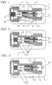
- the main body A of the device has a flat base 1 which is meant to be fixed around a hole of the life-jacket by heat-sealing or other suitable methods and perimetrically delimits the recess 2 into which the opening 3 leads.
- the opening 3 is provided in the cylindrical seat 4 in the portion that acts as a seat for the check valve, i.e., proximate to the front end of the seat which, by means of a choke 5 with radial slits, is connected to a threaded seat 6 into which a bottle of air or compressed gases is to be screwed.
- a slit 8 for a manual actuation lever L is also provided laterally and at the cylindrical seat 4 in the body A of the device, which is externally threaded at a rear end 7 in order to allow to screw thereon a cap B or a body M of a snap-action device.
- the lever L is pivoted by the insertion of a pivot R in a suitable seat 9 of the body A.
- the lever L is pivoted in R, can be activated by means of a cord and is almost entirely accommodated, when inactive, in the appropriately provided recess of the body A.
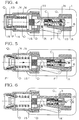
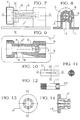
- An axial hole 12 ( Figure 12) is connected to the transverse slit 11, and the rear stem of the plunger C enters said hole for coupling. This is done so that the metal lever L acts directly on the plunger C rather than on the plastic extension D which acts as a support and guiding element for the plunger.
- Figure 3 shows the valve G and the gasket H in such a retracted position as to fully expose the opening 3, in practice this is not indispensable in order to achieve inflation of the life-jacket, since the gasket H provides a front seal and it therefore merely has to shift from its resting position to allow the flow to pass peripherally and in any case enter the opening 3.
- the invention provides for the screwing of a body M of a snap-action device in the rear end 7 of the main body A instead of the cap B.
- the device has a pusher N which is inserted in a helical spring O which acts between the flange 15 of the pusher and the flange 14 of a caliper P the jaws whereof, shaped so as to wedge into a groove 13 of the pusher N, keep the spring O compressed until they remain clamped by a ring Q which, being made of water-soluble or at least hygroscopic material, breaks quickly, decomposing or changing shape, when water flows in from the large hole 16 provided for this purpose on the bottom of the body M.
- the pusher N Since the pusher N is retained by resting with an inclined or wedge-shaped portion against a corresponding portion of the jaws of the caliper P, which are fastened by a ring Q made of paper or other suitable material, the breakage of the ring and the tension of the spring O allow the pusher to move, spacing the jaws apart while the flange 14 of said caliper continues to rest against an internal abutment of the body M.
- the pusher moves into abutment against the rear end of the body A and pushes axially, by means of the extension D, the plunger C, whose movement and related effects are identical to those which can otherwise be obtained by manually actuating the lever L, which instead has no effect in this circumstance.
Landscapes
- Engineering & Computer Science (AREA)
- Mechanical Engineering (AREA)
- Ocean & Marine Engineering (AREA)
- Closures For Containers (AREA)
- Massaging Devices (AREA)
- Emergency Lowering Means (AREA)
Applications Claiming Priority (2)
| Application Number | Priority Date | Filing Date | Title |
|---|---|---|---|
| ITFO970024 | 1997-10-10 | ||
| IT1997FO000024A IT1304337B1 (it) | 1997-10-10 | 1997-10-10 | Dispositivo con valvola,ad azionamento automatico e/o manuale, per ilgonfiaggio rapido dei giubbetti di salvataggio od altro |
Publications (2)
| Publication Number | Publication Date |
|---|---|
| EP0908652A2 true EP0908652A2 (de) | 1999-04-14 |
| EP0908652A3 EP0908652A3 (de) | 2000-09-20 |
Family
ID=11353562
Family Applications (1)
| Application Number | Title | Priority Date | Filing Date |
|---|---|---|---|
| EP98118327A Withdrawn EP0908652A3 (de) | 1997-10-10 | 1998-09-28 | Vorrichtung mit Ventil mit automatischer und/oder manueller Betätigung zum schnellen Auffblasen von Rettungswesten oder anderen Gegenständen |
Country Status (2)
| Country | Link |
|---|---|
| EP (1) | EP0908652A3 (de) |
| IT (1) | IT1304337B1 (de) |
Cited By (3)
| Publication number | Priority date | Publication date | Assignee | Title |
|---|---|---|---|---|
| WO2004096635A1 (en) * | 2003-04-26 | 2004-11-11 | P & P Utveckling Ab | Buoyancy body release device |
| EP2019779A4 (de) * | 2006-05-16 | 2009-06-17 | Halkey Roberts Corp | Heissversiegelbarer gasgenerator |
| JP2013545656A (ja) * | 2010-11-11 | 2013-12-26 | ユナイテッド・モルダーズ・リミテッド | 膨張デバイス機構 |
Family Cites Families (5)
| Publication number | Priority date | Publication date | Assignee | Title |
|---|---|---|---|---|
| US3169665A (en) * | 1962-08-01 | 1965-02-16 | Goodrich Co B F | Inflating apparatus |
| US4223805A (en) * | 1978-08-04 | 1980-09-23 | Mackal Glenn H | Automatic inflator |
| US4894036A (en) * | 1988-08-08 | 1990-01-16 | Switlik Parachute Company, Inc. | Inflator assembly for life vests |
| US5564478A (en) * | 1994-09-02 | 1996-10-15 | Halkey-Roberts Corporation | Heat sealable inflator |
| US5601124A (en) * | 1995-02-07 | 1997-02-11 | Halkey-Roberts Corporation | Autoinflator with apertured housing |
-
1997
- 1997-10-10 IT IT1997FO000024A patent/IT1304337B1/it active
-
1998
- 1998-09-28 EP EP98118327A patent/EP0908652A3/de not_active Withdrawn
Cited By (4)
| Publication number | Priority date | Publication date | Assignee | Title |
|---|---|---|---|---|
| WO2004096635A1 (en) * | 2003-04-26 | 2004-11-11 | P & P Utveckling Ab | Buoyancy body release device |
| EP2019779A4 (de) * | 2006-05-16 | 2009-06-17 | Halkey Roberts Corp | Heissversiegelbarer gasgenerator |
| AU2007254443B2 (en) * | 2006-05-16 | 2013-07-18 | Halkey-Roberts Corporation | Heat sealable inflator |
| JP2013545656A (ja) * | 2010-11-11 | 2013-12-26 | ユナイテッド・モルダーズ・リミテッド | 膨張デバイス機構 |
Also Published As
| Publication number | Publication date |
|---|---|
| ITFO970024A1 (it) | 1999-04-10 |
| ITFO970024A3 (it) | 1999-04-12 |
| IT1304337B1 (it) | 2001-03-15 |
| ITFO970024A0 (it) | 1997-10-10 |
| EP0908652A3 (de) | 2000-09-20 |
Similar Documents
| Publication | Publication Date | Title |
|---|---|---|
| KR100443939B1 (ko) | 밸브 연결기 | |
| US5902097A (en) | Pumping device with a clamping nozzle for various valves | |
| US5012954A (en) | Tire inflation system | |
| EP2868497A1 (de) | Ventilschaftbasierter, luftaufrechterhaltender Reifen und Verfahren | |
| AU683643B2 (en) | Fluid-operated spring brake actuator with improved pressure plate | |
| US5921269A (en) | Tire inflator | |
| US5839488A (en) | Hands-off low-air-loss quick-connect quick-disconnect fast-fill dunnage bag filling valve-nozzle assembly & system | |
| EP3797977B1 (de) | Antispritzverbindungsstruktur für die verbindung einer luftdüse eines reifens und eines verbindungsschlauchs eines luftkompressors | |
| US20020138975A1 (en) | Squeezing tool for coaxial cable connector | |
| US20180172167A1 (en) | Connector Structure of Air Connector Adapted to Connect Presta (French) Valve and Schrader (American) Valve | |
| EP1041282A2 (de) | Kohlendioxidpumpe für Reifen | |
| US5097580A (en) | Apparatus for installing and removing valve stems | |
| US4326407A (en) | Leak test tools | |
| EP0908652A2 (de) | Vorrichtung mit Ventil mit automatischer und/oder manueller Betätigung zum schnellen Auffblasen von Rettungswesten oder anderen Gegenständen | |
| US5628350A (en) | Inflating device | |
| AU624631B2 (en) | Bag puncturing means | |
| US8024849B2 (en) | Fire extinguisher | |
| US3189226A (en) | Calking assembly | |
| US5118140A (en) | Tool for smooth wall tubes | |
| US5852986A (en) | Automatic inflator with status indicators | |
| US4153096A (en) | Apparatus for introducing pressurized gas into a tire | |
| US5582223A (en) | Filling apparatus for gas bottle valves | |
| US6923200B2 (en) | Safety device for pressurizing an envelope at risk of bursting | |
| EP0690231A1 (de) | Luftdichte Schnellkupplung für Reifensicherheitsventile | |
| US4928724A (en) | Automatic wet tank drain valve |
Legal Events
| Date | Code | Title | Description |
|---|---|---|---|
| PUAI | Public reference made under article 153(3) epc to a published international application that has entered the european phase |
Free format text: ORIGINAL CODE: 0009012 |
|
| AK | Designated contracting states |
Kind code of ref document: A2 Designated state(s): BE CH ES FR GB GR IT LI NL PT |
|
| AX | Request for extension of the european patent |
Free format text: AL;LT;LV;MK;RO;SI |
|
| PUAL | Search report despatched |
Free format text: ORIGINAL CODE: 0009013 |
|
| AK | Designated contracting states |
Kind code of ref document: A3 Designated state(s): AT BE CH CY DE DK ES FI FR GB GR IE IT LI LU MC NL PT SE |
|
| AX | Request for extension of the european patent |
Free format text: AL;LT;LV;MK;RO;SI |
|
| RIC1 | Information provided on ipc code assigned before grant |
Free format text: 7F 16K 15/20 A, 7F 16K 15/06 B, 7B 63C 9/19 B, 7B 63C 9/24 B |
|
| 17P | Request for examination filed |
Effective date: 20010226 |
|
| AKX | Designation fees paid |
Free format text: BE CH ES FR GB GR IT LI NL PT |
|
| REG | Reference to a national code |
Ref country code: DE Ref legal event code: 8566 |
|
| 17Q | First examination report despatched |
Effective date: 20020228 |
|
| STAA | Information on the status of an ep patent application or granted ep patent |
Free format text: STATUS: THE APPLICATION HAS BEEN WITHDRAWN |
|
| 18W | Application withdrawn |
Effective date: 20030513 |