EP0908191B1 - Hollow fiber membrane oxygenator - Google Patents
Hollow fiber membrane oxygenator Download PDFInfo
- Publication number
- EP0908191B1 EP0908191B1 EP98119137A EP98119137A EP0908191B1 EP 0908191 B1 EP0908191 B1 EP 0908191B1 EP 98119137 A EP98119137 A EP 98119137A EP 98119137 A EP98119137 A EP 98119137A EP 0908191 B1 EP0908191 B1 EP 0908191B1
- Authority
- EP
- European Patent Office
- Prior art keywords
- hollow fiber
- fiber membrane
- blood
- oxygenator
- housing
- Prior art date
- Legal status (The legal status is an assumption and is not a legal conclusion. Google has not performed a legal analysis and makes no representation as to the accuracy of the status listed.)
- Expired - Lifetime
Links
Images


Classifications
-
- B—PERFORMING OPERATIONS; TRANSPORTING
- B01—PHYSICAL OR CHEMICAL PROCESSES OR APPARATUS IN GENERAL
- B01D—SEPARATION
- B01D67/00—Processes specially adapted for manufacturing semi-permeable membranes for separation processes or apparatus
- B01D67/0081—After-treatment of organic or inorganic membranes
- B01D67/0088—Physical treatment with compounds, e.g. swelling, coating or impregnation
-
- B—PERFORMING OPERATIONS; TRANSPORTING
- B01—PHYSICAL OR CHEMICAL PROCESSES OR APPARATUS IN GENERAL
- B01D—SEPARATION
- B01D63/00—Apparatus in general for separation processes using semi-permeable membranes
- B01D63/02—Hollow fibre modules
- B01D63/021—Manufacturing thereof
-
- B—PERFORMING OPERATIONS; TRANSPORTING
- B01—PHYSICAL OR CHEMICAL PROCESSES OR APPARATUS IN GENERAL
- B01D—SEPARATION
- B01D63/00—Apparatus in general for separation processes using semi-permeable membranes
- B01D63/02—Hollow fibre modules
- B01D63/021—Manufacturing thereof
- B01D63/0233—Manufacturing thereof forming the bundle
-
- B—PERFORMING OPERATIONS; TRANSPORTING
- B01—PHYSICAL OR CHEMICAL PROCESSES OR APPARATUS IN GENERAL
- B01D—SEPARATION
- B01D63/00—Apparatus in general for separation processes using semi-permeable membranes
- B01D63/02—Hollow fibre modules
- B01D63/025—Bobbin units
-
- Y—GENERAL TAGGING OF NEW TECHNOLOGICAL DEVELOPMENTS; GENERAL TAGGING OF CROSS-SECTIONAL TECHNOLOGIES SPANNING OVER SEVERAL SECTIONS OF THE IPC; TECHNICAL SUBJECTS COVERED BY FORMER USPC CROSS-REFERENCE ART COLLECTIONS [XRACs] AND DIGESTS
- Y10—TECHNICAL SUBJECTS COVERED BY FORMER USPC
- Y10S—TECHNICAL SUBJECTS COVERED BY FORMER USPC CROSS-REFERENCE ART COLLECTIONS [XRACs] AND DIGESTS
- Y10S128/00—Surgery
- Y10S128/23—Cervical collars
-
- Y—GENERAL TAGGING OF NEW TECHNOLOGICAL DEVELOPMENTS; GENERAL TAGGING OF CROSS-SECTIONAL TECHNOLOGIES SPANNING OVER SEVERAL SECTIONS OF THE IPC; TECHNICAL SUBJECTS COVERED BY FORMER USPC CROSS-REFERENCE ART COLLECTIONS [XRACs] AND DIGESTS
- Y10—TECHNICAL SUBJECTS COVERED BY FORMER USPC
- Y10S—TECHNICAL SUBJECTS COVERED BY FORMER USPC CROSS-REFERENCE ART COLLECTIONS [XRACs] AND DIGESTS
- Y10S261/00—Gas and liquid contact apparatus
- Y10S261/28—Blood oxygenators
Definitions
- the present invention relates to a hollow fiber membrane oxygenator for removing carbon dioxide from blood and oxygenating the blood in an extracorporeal blood circulation and, more particularly, to the hollow fiber membrane oxygenator of external blood circulation type.
- a generally employed hollow fiber membrane oxygenator using porous membrane has been widely applied to a device for extracorporeal blood circulation, a device for assisting cardiopulmonary blood circulation and the like used in cardiotomy operated for cardiopathy.
- the membrane type oxygenator is composed mainly of hollow fiber membranes through which gas is transferred, i.e., oxygen is admitted into blood and carbon dioxide is removed from blood.
- Two methods of blood circulation to the membrane type oxygenator can be used, one is an internal perfusion method and the other is an external perfusion method.
- the former method allows blood to flow to the inner side of the hollow fiber membranes and gas to flow to the outer side thereof.
- the latter method allows blood to flow to the outer side of the hollow fiber membranes and gas to flow to the inner side thereof.
- the membrane type oxygenator of external perfusion type has become more popular than that of internal perfusion type because of higher mass transfer capability and lower degree of pressure loss.
- the aforementioned membrane type oxygenator of external perfusion type tends to cause turbulence in the blood flow, which is likely to adversely affect adhesion and activation characteristics of blood platelet.
- the oxygenator of internal perfusion type may be considered to be superior to the external perfusion type.
- Japanese Patent Application Laid-Open No. 62-172961 discloses a membrane type oxygenator coated with benzylalkylammonium-heparin composite. This oxygenator, however, causes exfoliation of the composite into blood during its operation.
- the above-described oxygenator may be coated with hydrophilic polymer.
- the blood plasma component when using porous membranes for gas transfer, the blood plasma component will penetrate into micropores and leak through the membrane, thus degrading gas transfer capability.
- Japanese Patent Application Laid-Open No. 4-152952 discloses biocompatible material formed of alkoxyalkyl(meth)acrylate, which can be applied to the membrane of the membrane type oxygenator.
- the hollow fiber membrane for the membrane type oxygenator is coated with alkoxyalkyl(meth)acrylate using methanol solution thereof, it flows into micropores of the hollow fiber membrane.
- the blood plasma component will penetrate into micropores during operation of the oxygenator and leak through the membrane, thus degrading the gas transfer capability.
- a hollow fiber membrane oxygenator comprising a housing and a lot of porous hollow fiber having a large number of porous hollow fiber membranes for gas transfer housed in the housing, allowing blood to flow through outer surface of the hollow fiber membrane and oxygen-containing gas to flow through inside thereof.
- an outer surface or an outer layer of the hollow fiber membrane as a blood-contacting portion is coated with synthetic polymer mainly formed of alkoxyalkyl(meth)acrylate containing a C(1-4)alkoxy group and a C(1-4)alkyl group; and an intermediate layer or an inner layer of the hollow fiber membrane has substantially no synthetic polymer existing therein.
- a hollow fiber membrane oxygenator comprising a housing and a lot of porous hollow fiber membranes for gas transfer housed in the housing, allowing blood to flow through outer surface of the hollow fiber membrane and oxygen-containing gas to flow through inside thereof.
- an outer surface or an outer layer of the hollow fiber membrane as a blood-contacting portion is coated with synthetic polymer mainly formed of alkoxyalkyl(meth)acrylate containing repetitive combination of the unit shown in the following chemical formula 1; (where R 1 represents C(1-4)alkylene, R 2 represents C(1-4)alkyl, and R 3 represents H or CH 3 respectively.) and an intermediate layer or an inner layer of the hollow fiber membrane has substantially no synthetic polymer existing therein.
- the hollow fiber membrane oxygenator of external blood circulation type of the present invention will be described with reference to embodiments.
- Fig. 1 is a sectional view of an embodiment of the hollow fiber membrane oxygenator of external blood circulation type according to the present invention.
- Fig. 2 is an enlarged sectional view of a porous hollow fiber membrane for gas transfer, which is employed in the hollow fiber membrane oxygenator of external blood circulation type according to the present invention.
- Fig. 3 is a sectional view of another embodiment of the hollow fiber membrane oxygenator of external blood circulation type according to the present invention.
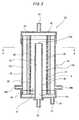
- a hollow fiber membrane oxygenator of external blood circulation type (hereinafter simply referred to as an oxygenator) 1 has the housing 2 and a lot of porous hollow fiber membranes 3 for gas transfer housed in a housing 2.
- an oxygenator 1 blood flows along the outer side of the hollow fiber membranes 3, whereas oxygen-containing gas flows along the inner side thereof.
- An outer surface or outer layer 3a of the hollow fiber membrane 3 as a blood-contacting portion is coated with synthetic polymer 18 mainly formed of alkoxyalkyl(meth)acrylate containing a C(1-4)alkoxy group and a C(1-4)alkyl group.
- An intermediate layer 3b and inner layer 3c of the hollow fiber membranes 3 contain substantially no synthetic polymer.
- the oxygenator 1 has a housing 2 and a lot of porous hollow fiber membranes 3 for gas transfer housed in the housing 2.
- blood flows along the outer side of the hollow fiber membrane 3 and oxygen-containing gas flows along the inner side thereof as the blood-contacting portion.
- the outer surface or the outer layer 3a of the hollow fiber membrane 3 is coated with the synthetic polymer 18 mainly formed of alkoxyalkyl(meth)acrylate containing repetitive combination of the unit as shown in chemical formula 1.
- the intermediate layer 3b and inner layer 3c of the hollow fiber membrane 3 contain substantially no synthetic polymer. (where R 1 represents C(1-4)alkylene, R 2 represents C(1-4)alkyl, and R 3 represents H or CH 3 respectively.)
- the oxygenator 1 of this embodiment is provided with a housing 2 having a blood inlet 6 and a blood outlet 7, a hollow fiber membrane bundle including a large number of porous hollow fiber membranes 3 for gas transfer disposed in the housing 2, a pair of partitions 4,5 for supporting both ends of the hollow fiber membrane bundle fluid-tightly, a blood chamber 12 defined by the partitions 4,5, the inner side of the housing 2 and the outer side of the hollow fiber membrane 3, a gas chamber formed in the hollow fiber membrane 3, and a gas inlet 8 and a gas outlet 9 communicated with the gas chamber or an inner space of the hollow fiber membrane 3,.
- the oxygenator 1 is provided with the tubular housing 2, a collective of a plurality of hollow fiber membranes 3 for gas transfer disposed in the tubular housing 2, and partitions 4,5 for holding both ends of the hollow fiber membrane 3 fluid-tightly in the housing 2.
- the inner space of the tubular housing 2 is divided into a first fluid chamber, i.e., a blood chamber 12 and a second fluid chamber, i.e., a gas chamber.
- the tubular housing 2 is further provided with a blood inlet 6 and a blood outlet 7 communicated with the blood chamber 12.
- a cap-like gas inflow header 10 having the gas inlet 8 as a second fluid inlet communicated with the inner space of the hollow fiber membrane 3, i.e., gas chamber.
- a gas inflow chamber 13 is defined by the outer surface of the partition 4 and the inner surface of the gas inflow header 10. The gas inflow chamber 13 is communicated with the gas chamber formed in the inner space of the hollow fiber membrane 3.
- a cap-like gas outflow header 11 having the gas outlet 9 as a second fluid outlet communicated with the inner space of the hollow fiber membrane 3.
- a gas outflow chamber 14 is defined by the outer surface of the partition 5 and the inner surface of the gas outflow header 11.
- the hollow fiber membrane 3 is formed as a porous membrane having its inside diameter ranging from 100 to 1,000 ⁇ m.
- the thickness of the hollow fiber membrane 3 ranges from 5 to 200 ⁇ m, preferably from 10 to 100 ⁇ m, or more preferably, from 10 to 20 ⁇ m.
- the porosity ranges from 5 to 90 %, preferably from 10 to 80 %, or more preferably, from 30 to 60 %.
- the micropore size ranges from 0.01 to 5 ⁇ m or preferably from 0.01 to 1 ⁇ m.
- the porous fiber membrane can be formed of hydrophobic polymer material such as polypropylene, polyethylene, polysulfone, polyacrylonitrile, polytetrafluoroethylene, and cellulose acetate. It is preferable to produce the porous fiber membrane using polyolefin resin, especially, polypropylene. It is further preferable to form micropores on the side wall using drawing or orienting method or solid phase/liquid phase separation method.
- the tubular housing 2 is formed of a hydrophobic synthetic resin material, for example, polycarbonate, acryl-styrene-copolymer, acryl-butylene-styrene copolymer.
- the housing 2 is, for example, tubular shaped and preferably transparent such that the inside thereof can be easily observed.
- a large number of porous hollow fiber membranes 3 from 5,000 to 100,000 are axially aligned in parallel with one another.
- Those hollow fiber membranes 3 are kept static by partitions 4, 5 fluid-tightly, each having both ends open to the respective ends of the housing 2.
- the partitions 4, 5 are formed of a potting agent, for example, polyurethane, silicone rubber or the like.
- the inner space of the housing 2 interposed between the partitions 4 and 5 is further parted into a gas chamber at the inner side of the hollow fiber membrane 3 and a blood chamber 12 at the outer side thereof.
- a gas inflow header 10 having a gas inlet 8 and a gas outflow header 11 having a gas outlet 9.
- Those headers 10, 11 are formed of hydrophobic synthetic resin material used for forming the housing 2.
- the headers 10, 11 are attached to the housing 2 through fusion using ultrasonic, high frequency, induction heating and the like. They can be adhered to the housing 2 using adhesive or mechanically fitted therewith. Alternatively they can be fixed to the housing 2 with a tightening ring (not shown). Consequently the whole area of the blood-contacting portion of the oxygenator 1 (inner side of the housing 2 and outer side of the hollow fiber membrane 3) is formed of the hydrophobic material.
- At least the blood-contacting portion of the oxygenator 1, i.e., outer surface or outer layer 3a of the hollow fiber membrane 3 is coated with, for example, synthetic polymer 18 mainly formed of alkoxyalkyl(meth)acrylate containing a C(1-4)alkoxy group and a C(1-4)alkyl group, or a synthetic polymer 18 mainly formed of alkoxyalkyl(meth)acrylate containing repetitive combination of the unit shown in the chemical formula 1.
- an intermediate layer 3b or an inner side 3c of the hollow fiber membrane 3 contains substantially no such synthetic polymer.
- the intermediate layer 3b or the inner layer 3c of the hollow fiber membrane 3 maintains hydrophobic characteristics exhibited by the base material thereof, thus preventing leakage of the blood plasma component. Especially it is preferable that substantially no synthetic polymer exist in the intermediate layer 3b and inner layer 3c of the hollow fiber membrane 3.
- the hollow fiber membrane 3 has a path 3d constituting the gas chamber at its center.
- the outer surface or the outer layer 3a of the hollow fiber membrane 3 (referred as the outer layer in this embodiment) as the blood-contacting portion is coated with the synthetic polymer 18, adhesion and activation of the blood platelet can be minimized.
- the intermediate layer 3b and the inner layer 3c of the hollow fiber membrane 3 contains substantially no synthetic polymer, they maintain hydrophobic characteristic of the base material of the membrane, thus preventing leakage of the blood plasma component with high efficiency.
- the aforementioned synthetic polymer may be used to coat not only the hollow fiber membranes of the oxygenator but also whole surface of the blood-contacting portion for minimizing adhesion and activation of the blood platelet. Additionally as the contact angle of the blood-contacting portion is lowered, priming process can be simplified.
- the hollow fiber membrane or a part thereof other than the blood-contacting portion does not have to be coated with the synthetic polymer. There may be no problem if the synthetic polymer is not applied to coat the portion that is not in contact with blood.
- the synthetic polymer is mainly formed of alkoxyalkyl(meth)acrylate.
- the synthetic polymer contains alkoxyalkyl(meth)acrylate for a main component.
- alkoxyalkyl(meth)acrylate is formed of homopolymer or copolymer of one or more kinds selected from the following alkoxyalkyl(meth)acrylate, or copolymer of the alkoxyalkyl(meth)acrylate and monomer copolymerizable therewith.
- the alkoxyalkyl(meth)acrylate contains both alkoxyalkylacrylate and alkoxyalkylmethacrylate, for example, methoxymethylacrylate, methoxyethylacrylate, methoxypropylacrylate, ethoxymethylacrylate, ethoxyethylacrylate, ethoxypropylacrylate, ethoxybutylacrylate, propoxymethylacrylate, butoxyethylacrylate, methoxybutylacrylate, methoxymethylmethacrylate, methoxyethylmethacrylate, ethoxymethylmethacrylate, ethoxyethylmethacrylate, propoxymethylmethacrylate, butoxyethylmethacrylate. Especially it is preferable to use methoxyethylacrylate.
- the following monomer can be copolymerized with alkoxyalkyl(meth)acrylate: methylacrylate, ethylacrylate, propylacrylate, butylacrylate, 2-ethylhexylacrylate, methylmethacrylate, ethylmethacrylate, butylmethacrylate, hexylacrylate, hexylmethacrylate, ethylene, propylene and the like.
- the copolymerizable monomer does not contain hydroxyl group or cationic group.
- the copolymer, formed of either random copolymer, block copolymer, or graft copolymer can be synthesized using a generally employed method, for example, radical polymerization, ion polymerization and polymerization using macromer.
- the ratio of the copolymerizable monomer to any copolymer is equal to or less than 50 %. If the ratio exceeds 50 the effect derived from alkoxyalkyl(meth)acrylate will be deteriorated.
- the weight-average molecular weight of the thus obtained alkoxylalkyl(meth)acrylate copolymer ranges from 10,000 to 1,000,000, and more preferably from 20,000 to 100,000.
- a hollow fiber membrane oxygenator of external blood circulation type (hereinafter simply referred to as an oxygenator) of another embodiment shown in Fig. 3 can also be used.
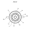
- An oxygenator 20 of this embodiment is provided with an inner tubular member 31 having blood holes 32 formed on its side, a tubular hollow fiber membrane bundle 22 containing a large number of porous hollow fiber membranes for gas transfer wound around outer surface of the inner tubular member 31, a housing 23 for holding the tubular hollow fiber membrane bundle 22 as well as the inner tubular member 31, partitions 25, 26 for keeping both ends of the tubular hollow fiber membrane bundle 22 static to the housing while keeping both ends of the hollow fiber membrane 3 open, a blood inlet 28 and a blood outlet 29 communicated with a blood chamber 17 formed in the housing 23, and a gas inlet 24 and a gas outlet 27 communicated with the inner side of the hollow fiber membrane 3.
- Fig. 3 is a sectional view of the hollow fiber membrane oxygenator according to another embodiment of the present invention.
- Fig. 4 is a sectional view taken along line A-A of Fig. 3.
- the housing 23 of the oxygenator 20 has an outer tubular member 33 for housing the inner tubular member 31 therein.
- the tubular hollow fiber membrane bundle 22 is disposed between the inner tubular member 31 and the outer tubular member 33.
- the housing 23 has either one of the blood inlet or the blood outlet communicated with the inner side of the inner tubular member and the other one of the blood inlet or the blood outlet communicated with the inner side of the outer tubular member.
- the housing 23 of the oxygenator 20 is provided with the outer tubular member 33 and an inner tubular body 35 disposed within the inner tubular member 31 and having its top end open therein.
- the inner tubular body 35 has a blood inlet 28 at its (lower) end.
- Outwardly extending two blood outlets 29a, 29b are formed at each side of the outer tubular member. Only one blood outlet can work sufficiently.
- the tubular hollow fiber membrane bundle 22 is wound around the outer surface of the inner tubular member 31. That is, the inner tubular member 31 serves as a core of the tubular hollow fiber membrane bundle 22.
- the inner tubular body 35 disposed within the inner tubular member 31 has its top end open in the vicinity of the first partition 25.
- the blood inlet 28 is formed at lower end extending from the inner tubular member 31.
- the inner tubular body 35, the inner tubular member 31 having its outer surface wound with the hollow fiber membrane bundle 22 and the outer tubular member 33 are substantially concentrically arranged.
- the relationship between one (upper) end of the inner tubular member 31 having its outer surface wound with the hollow fiber membrane bundle 22 and one (upper) end of the outer tubular member 33 is kept to be concentric with the first partition 25.
- the inside of the inner tubular member and the space defined by the outer tubular member 33 and the outer surface of the hollow fiber membrane are kept fluid-tightly so as not to communicate with the external portion.
- the portion slightly above the blood inlet 28 of the inner tubular body 35, the other (lower) end of the inner tubular member 31 having its outer surface wound with the hollow fiber membrane bundle 22 and the other (lower) end of the outer tubular member 33 are concentrically arranged with the second partition 26.
- the space defined by the inner tubular body 35 and the inside of the inner tubular member and the space defined by the outer tubular member 33 and the outer surface of the hollow fiber membrane are kept fluid-tightly so as not to communicate with the external portion.
- the partitions 25, 26 are formed of a potting agent, for example, polyurethane, silicone rubber or the like.
- the oxygenator 20 of this embodiment has a blood chamber 17 composed of a blood inflow portion 17a forming the inner space of the inner tubular body 35, a first blood chamber 17b forming substantially a tubular space defined by the inner tubular body 35 and the inner tubular member, and a second blood chamber 17c forming substantially a tubular space defined by the hollow fiber membrane bundle 22 and the outer tubular member 33.
- blood flows into the blood inflow portion 17a to flow upwards within the inner tubular body 35 (blood inflow portion 17a) to flow out from an upper end 35a (open end) of the inner tubular body 35.
- the blood further flows into the first blood chamber 17b to pass through the opening 32 formed in the inner tubular member 31 and contacts the hollow fiber membranes for gas transfer. Then the blood flows into the second blood chamber 17c to flow out through the blood outlets 29a, 29b.
- a gas inflow member 41 Fixed to one end of the outer tubular member 33 is a gas inflow member 41 having a gas inlet 24. Likewise fixed to the other end of the outer tubular member 33 is a gas outflow member 42 having a gas outlet 27. The blood inlet 28 of the inner tubular body 35 downwardly extends through the gas outflow member 42.
- the outer tubular member 33 can be formed into annular shape, polygonal shape, and elliptic shape in cross section. Preferably it is formed into the annular shape.
- the inside diameter of the outer tubular member preferably ranges from 32 to 164 mm and the effective length (a whole length excluding the portion surrounded with the partition) ranges from 10 to 730 mm.
- the inner tubular member 31 may have annular shape, polygonal shape, and elliptic shape in cross section. Preferably it is formed into the annular shape.
- the outside diameter of the inner tubular member preferably ranges from 20 to 100 mm.
- the effective length (a whole length excluding the portion surrounded with the partition) preferably ranges from 10 to 730 mm.
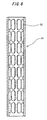
- the inner tubular member 31 has a large number of blood openings 32 at its side. The total area of these blood openings 32 is preferably maximized while maintaining the required strength of the tubular member.
- Fig. 5 representing a front view of the inner tubular member
- Fig. 6 representing a longitudinal sectional view of the center of the inner tubular member
- Fig. 7 representing a view taken along line B-B of Fig.
- a plurality of annular openings 32 are formed at a uniform interval around an outer periphery of the inner tubular member.
- a plurality of groups of the annular openings 32 are further formed at a uniform interval across the length of the inner tubular member (8 groups in this embodiment).
- the opening may have either circular, polygonal, or elliptic shape. However it is preferable to form the opening into the elliptic shape as shown in Fig. 5.
- the inner tubular body 35 may have annular shape, polygonal shape, and elliptic shape in cross section. Preferably it is formed into the annular shape.
- the distance between the opening at top end of the inner tubular body 35 and the first partition 25 preferably ranges from 20 to 50 mm.
- the inside diameter of the inner tubular body 35 preferably ranges from 10 to 30 mm.
- the thickness of the tubular hollow fiber membrane bundle 22 ranges from 5 to 35 mm, especially from 10 to 28 mm.
- the loading density of the hollow fiber membrane to the tubular space defined by the outer side of the tubular hollow fiber membrane bundle 22 and the inner side thereof preferably ranges from 40 to 85 %, especially from 45 to 80 %.
- the outside diameter of the hollow fiber membrane bundle 22 preferably ranges from 30 to 170 mm, especially from 70 to 130 mm.
- the membrane can be used for the purpose of gas transfer as described above.
- the hollow fiber membrane bundle 22 is formed in the following process.
- the hollow fiber membranes are wound around the inner tubular member 31 to form a hollow fiber membrane bobbin, utilizing the inner tubular member 31 as the core thereof. Both ends of the thus formed hollow fiber membrane bobbin are fixed to the partitions and are cut off, together with the inner tubular member 31 as the core. As a result, both ends of the hollow fiber membranes are open to the outer surface of the partition.
- the interval between the hollow fiber membranes adjacent to each other is preferably set to 1/10 to 1/1 of the outside diameter of the hollow fiber membranes. More specifically, the interval between the adjacent fiber membranes is set to the value preferably from 30 to 200 ⁇ m and, more preferably from 50 to 180 ⁇ m.
- the hollow fiber membrane bundle 22 by winding the hollow fiber membranes one by one or a combination of a plurality thereof around the inner tubular member 31 such that they are substantially in parallel with one another and spaced at substantially a regular interval.
- the above-described method of forming the hollow fiber membrane bundle 22 minimizes non-uniformity in the blood flow.
- the above-described integer (n) representing the relationship between the number of rotations of the winding rotary member and the number of reciprocations of the winder should be set to 1 to 5 and preferably from 2 to 4.
- the oxygenator described in this embodiment is constructed to allow blood to flow and pass through the hollow fiber membrane bundle 22 from inner side thereof, further flow outside the hollow fiber membrane bundle 22 and flow out from the oxygenator 20.
- the oxygenator 20 of the present invention is not limited to this type.
- the oxygenator 20 can be constructed to allow blood to flow and pass through the hollow fiber membrane bundle 22 from outer side thereof, further flow inside the hollow fiber membrane bundle 22, and flow out from the oxygenator 20.
- the outer side or the outer layer 3a of the hollow fiber membrane 3 is coated with synthetic polymer mainly formed of alkoxyalkyl(meth)acrylate containing a C(1-4)alkoxy group and a C(1-4)alkyl group, or synthetic polymer 18 mainly formed of alkoxyalkyl(meta)acrylate containing repetitive combination of the unit shown in the above chemical formula 1.
- the intermediate layer 3b and the inner layer 3c of the hollow fiber membrane 3 contain substantially no synthetic polymer.
- the hollow fiber membrane 3 has a path 3d constituting the gas chamber formed at the center thereof.
- the hollow fiber membranes of the oxygenator 20 are sequentially laminated in contact with each other to form a bobbin-like structure having complicated blood path and a large number of narrow portions. Therefore this type of oxygenator has an excellent gas transfer capability. On the other hand, it may be inferior to the oxygenator of external blood circulation type which is not formed into the bobbin-like structure in view of adhesion and activation characteristics of the blood platelet.
- the outer surface or the outer layer 3a of the hollow fiber membrane 3 (referred as the outer layer in this embodiment) as the blood-contacting portion of the hollow fiber membrane of the oxygenator 20 is coated with the aforementioned synthetic polymer 18.
- the outer layer in this embodiment As a result, adhesion and activation of the blood platelet at the blood-contacting surface of the hollow fiber membrane 3 can be minimized.
- the synthetic polymer may be used to coat not only the hollow fiber membranes but also a whole area of blood-contacting portion of the oxygenator.
- the hollow fiber membrane or a part thereof other than the blood-contacting portion (for example, the portion surrounded with the partition, the contact portion between the hollow fiber membranes) does not have to be coated with the synthetic polymer.
- Described below is a method of producing the hollow fiber membrane oxygenator of external blood circulation type.
- the oxygenator (for example, having a structure as shown in Fig. 1 or Fig. 3) is fabricated. Then liquid containing synthetic polymer mainly formed of the aforementioned alkoxyalkyl(meth)acrylate or the solution thereof is supplied to flow through the blood path of the oxygenator such that the blood-contacting portion is coated with the aforementioned synthetic polymer.
- solubility parameter value Solubility parameter of A x Volume of A/Total volume + Solubility parameter of B x Volume of B/Total volume
- solubility parameter value Solubility parameter of A x Volume of A/Total volume + Solubility parameter of B x Volume of B/Total volume + Solubility parameter of C x Volume of C/Total volume
- a solvent which cannot penetrate into the micropore of the hollow fiber membrane to reach its center It is, thus, preferable to use a solvent containing water to some extent.
- two-component solvent containing water and alcohol, more specifically, mixture of water, methanol and ethanol.
- Concentration of alkoxyalkyl(meth)acrylate contained in the solvent ranges from 0.01 to 5.0 wt.%, and preferably from 0.1 to 1.0 wt.%.
- the hollow fiber membrane may be subjected to coating of the synthetic polymer solution prior to fabrication of the oxygenator.
- the coating method known to those skilled in the art can be used, for example, dipping process, spray process and the like using polymer solution.
- a synthetic polymer coated to the outer surface or the outer layer of said hollow fiber membrane is preferable a solidification material of a solution of the synthetic polymer using a solvent having a solubility parameter value ranging from 38 to 40 (MPa) 1/2 .
- the solvent is preferable a mixture of water and alcohol.
- the solvent is more preferable a mixture of water, methanol and ethanol.
- the synthetic polymer solution (concentration: 0.5 wt.%) was prepared by dissolving polymethoxyethylacrylate (average molecular weight : 70,000) in the solvent containing water, methanol and ethanol by ratio of 6:1:3 (solubility parameter value to polymethoxyethylacrylate : 38.8(MPa) 1/2 ).
- the prepared synthetic polymer solution was supplied to the blood path side of the oxygenator to coat the whole area of the blood-contacting portion thereof with the synthetic polymer. Then the hollow fiber membrane oxygenator of external blood circulation type according to the present invention was fabricated.
- the hollow fiber membrane oxygenator having the blood-contacting portion not coated with the aforementioned synthetic polymer was prepared as a comparative example 1.
- the synthetic polymer solution (concentration : 0.5 wt.%) was prepared by dissolving polymethoxyethylacrylate (average molecular weight: 70,000) identical to the one used in the embodiment 1 in single-component solvent of methanol (solubility parameter value to polymethoxyethylacrylate : 29.7 (MPa) 1/2 ).
- the thus prepared synthetic polymer solution was supplied to the blood path of the oxygenator to coat the whole area of the blood-contacting portion thereof with the synthetic polymer. Then the oxygenator as a comparative example 3 was fabricated.
- Each oxygenator of the embodiment 1 and comparative examples 1 to 3 was incorporated with the extracorporeal blood circulation circuit and filled with 200 ml of freshly collected blood containing added heparin and 350 ml of Ringer solution containing lactic acid.
- the blood kept at 37 °C was perfused within the circuit at 1 L/min. for 4 hours.
- the number of blood platelet and ⁇ -TG were measured.
- Tables 1 and 2 show the respective measurement results.
- the term ⁇ -TG represents the degree of activation of the blood platelet. After blood circulation, it was checked for any leakage of blood plasma. Table 3 shows the check result.
- the inner tubular member used in this embodiment had a shape shown in Figs. 5 to 7, an outside diameter of 50 mm and a length of 188 mm.
- Four hollow fiber membranes made of porous polypropylene and each having inside diameter of 195 ⁇ m, outside diameter of 295 ⁇ m and porosity of about 35 % were wound around the inner tubular member at a regular interval.
- a hollow fiber membrane bobbin was formed by winding a plurality of hollow fiber membranes adjacent to the hollow fiber membrane of the four hollow fiber membranes at the same interval as being set for the previously wound membranes.
- the hollow fiber membrane bobbin was accommodated in the outer tubular member.
- One end of the hollow fiber membrane bobbin was fixed with a potting agent and then cut off.
- the inner tubular body was inserted into the hollow fiber membrane bobbin. Thereafter, the other end of the bobbin was fixed with the potting agent.
- the other end of the hollow fiber membrane bobbin was cut off without cutting the inner tubular body by rotating the hollow fiber membrane bobbin while keeping the inner tubular body centered. Then a gas inflow member and a gas outflow member were installed.
- an oxygenator having a hollow fiber membrane bundle constructed as shown in Fig. 3 was prepared.
- the area of each hollow fiber membrane was set to 2.5 m 2 .
- the interval between the hollow fiber membranes was 50 ⁇ m
- the thickness of the hollow fiber membrane bundle was 10 mm
- effective length thereof was 153 mm
- the loading density in the area defined by the hollow fiber membrane bundle was 65 %.
- the synthetic polymer solution (concentration: 0.5 wt.% ) was prepared by dissolving polymethoxyethylacrylate (average molecular weight : 70,000) in the solvent containing mixture of water, methanol and ethanol by ratio of 6:1:3 (solubility parameter to polymethoxyethylacrylate : 38.8 (MPa) 1/2 ).
- the thus prepared synthetic polymer solution was supplied to the aforementioned blood path of the oxygenator such that the whole area of the blood-contacting portion of the oxygenator is coated with the synthetic polymer.
- the oxygenator having the blood-contacting portion uncoated with the synthetic polymer was used as the comparative example 5.
- the synthetic polymer solution (concentration : 0.5 wt.%) was prepared by dissolving polymethoxyethylacrylate (average molecular weight: 70,000) identical to the one used in the embodiment 1 in the single-component solvent of methanol (solubility parameter value to polymethoxyethylacrylate : 29.7 (MPa) 1/2 ).
- the thus prepared synthetic polymer solution was supplied to the blood path of the oxygenator to coat the whole area of the blood-contacting portion thereof with the synthetic polymer.
- the oxygenator was fabricated as in the comparative example 6.
- Each oxygenator of embodiment 2 and comparative examples 5, 6 was incorporated within the extracorporeal blood circulation circuit and filled with 200 ml of freshly collected blood containing added heparin and 350 ml of Ringer solution containing lactic acid.
- the blood kept at 37 °C was perfused within the circuit at 1 L/min. for 4 hours.
- the number of blood platelet and ⁇ -TG were measured.
- Tables 4 and 5 show the respective measurement results.
- the term ⁇ -TG represents the degree of activation of the blood platelet. After blood circulation, it was checked for any leakage of blood plasma. Table 6 shows the check result.
- the outer surface or the outer layer of the hollow fiber membrane as the blood-contacting portion of the hollow fiber membrane is coated with the aforementioned synthetic polymer.
- the synthetic polymer does not exist in the intermediate layer and inner layer of the hollow fiber membrane, the intermediate layer and inner layer of the hollow fiber membrane maintain hydrophobic capability exhibited by the base material of the membrane, thus preventing the leakage of the blood plasma.
Description
- The present invention relates to a hollow fiber membrane oxygenator for removing carbon dioxide from blood and oxygenating the blood in an extracorporeal blood circulation and, more particularly, to the hollow fiber membrane oxygenator of external blood circulation type.
- A generally employed hollow fiber membrane oxygenator using porous membrane has been widely applied to a device for extracorporeal blood circulation, a device for assisting cardiopulmonary blood circulation and the like used in cardiotomy operated for cardiopathy. The membrane type oxygenator is composed mainly of hollow fiber membranes through which gas is transferred, i.e., oxygen is admitted into blood and carbon dioxide is removed from blood.
- Two methods of blood circulation to the membrane type oxygenator can be used, one is an internal perfusion method and the other is an external perfusion method. The former method allows blood to flow to the inner side of the hollow fiber membranes and gas to flow to the outer side thereof. The latter method allows blood to flow to the outer side of the hollow fiber membranes and gas to flow to the inner side thereof.
- The membrane type oxygenator of external perfusion type has become more popular than that of internal perfusion type because of higher mass transfer capability and lower degree of pressure loss. The aforementioned membrane type oxygenator of external perfusion type, however, tends to cause turbulence in the blood flow, which is likely to adversely affect adhesion and activation characteristics of blood platelet. In view of the above-described aspect, the oxygenator of internal perfusion type may be considered to be superior to the external perfusion type.
- Japanese Patent Application Laid-Open No. 62-172961 discloses a membrane type oxygenator coated with benzylalkylammonium-heparin composite. This oxygenator, however, causes exfoliation of the composite into blood during its operation.
- The above-described oxygenator may be coated with hydrophilic polymer. In such a case, when using porous membranes for gas transfer, the blood plasma component will penetrate into micropores and leak through the membrane, thus degrading gas transfer capability.
- Japanese Patent Application Laid-Open No. 4-152952 discloses biocompatible material formed of alkoxyalkyl(meth)acrylate, which can be applied to the membrane of the membrane type oxygenator. However it is practically difficult to form the hollow fiber membrane for the membrane type oxygenator directly from the alkoxyalkyl(meth)acrylate. If the hollow fiber membrane for the membrane type oxygenator is coated with alkoxyalkyl(meth)acrylate using methanol solution thereof, it flows into micropores of the hollow fiber membrane. As a result, the blood plasma component will penetrate into micropores during operation of the oxygenator and leak through the membrane, thus degrading the gas transfer capability.
- In view of foregoing, it is an object of the present invention to provide a hollow fiber membrane oxygenator of external blood circulation type which minimizes adhesion and activation of the blood platelet and prevents leakage of blood plasma component.
- In order to achieve the object, there is provided a hollow fiber membrane oxygenator comprising a housing and a lot of porous hollow fiber having a large number of porous hollow fiber membranes for gas transfer housed in the housing, allowing blood to flow through outer surface of the hollow fiber membrane and oxygen-containing gas to flow through inside thereof. In the hollow fiber membrane oxygenator, an outer surface or an outer layer of the hollow fiber membrane as a blood-contacting portion is coated with synthetic polymer mainly formed of alkoxyalkyl(meth)acrylate containing a C(1-4)alkoxy group and a C(1-4)alkyl group; and an intermediate layer or an inner layer of the hollow fiber membrane has substantially no synthetic polymer existing therein.
- In order to further achieve the object, there is provided a hollow fiber membrane oxygenator comprising a housing and a lot of porous hollow fiber membranes for gas transfer housed in the housing, allowing blood to flow through outer surface of the hollow fiber membrane and oxygen-containing gas to flow through inside thereof. In the hollow fiber membrane oxygenator, an outer surface or an outer layer of the hollow fiber membrane as a blood-contacting portion is coated with synthetic polymer mainly formed of alkoxyalkyl(meth)acrylate containing repetitive combination of the unit shown in the following
chemical formula 1;(where R1 represents C(1-4)alkylene, R2 represents C(1-4)alkyl, and R3 represents H or CH3 respectively.)
and an intermediate layer or an inner layer of the hollow fiber membrane has substantially no synthetic polymer existing therein. - The foregoing and further objects, features and advantages of the present invention will become apparent from the following description of various embodiments with reference to the accompanying drawings, wherein like numerals are used to represent like elements and wherein:
- Fig. 1 is a sectional view of an embodiment of a hollow fiber membrane oxygenator of external blood circulation type according to the present invention;
- Fig. 2 is an enlarged sectional view of a hollow fiber membrane employed in the hollow fiber membrane oxygenator of external blood circulation type according to the present invention;
- Fig. 3 is a sectional view of another embodiment of the hollow fiber membrane oxygenator of external blood circulation type according to the present invention;
- Fig. 4 is a sectional view taken along line A-A of Fig. 3;
- Fig. 5 is a front view of an example of an inner tubular member employed in the hollow fiber membrane oxygenator of external blood circulation type according to the present invention;
- Fig. 6 is a longitudinal sectional view of the center of the inner tubular member shown in Fig. 5; and
- Fig. 7 is a sectional view taken along line B-B of Fig. 5.
-
- The hollow fiber membrane oxygenator of external blood circulation type of the present invention will be described with reference to embodiments.
- Fig. 1 is a sectional view of an embodiment of the hollow fiber membrane oxygenator of external blood circulation type according to the present invention. Fig. 2 is an enlarged sectional view of a porous hollow fiber membrane for gas transfer, which is employed in the hollow fiber membrane oxygenator of external blood circulation type according to the present invention. Fig. 3 is a sectional view of another embodiment of the hollow fiber membrane oxygenator of external blood circulation type according to the present invention.
- A hollow fiber membrane oxygenator of external blood circulation type (hereinafter simply referred to as an oxygenator) 1 has the housing 2 and a lot of porous
hollow fiber membranes 3 for gas transfer housed in a housing 2. In theoxygenator 1, blood flows along the outer side of thehollow fiber membranes 3, whereas oxygen-containing gas flows along the inner side thereof. An outer surface orouter layer 3a of thehollow fiber membrane 3 as a blood-contacting portion is coated withsynthetic polymer 18 mainly formed of alkoxyalkyl(meth)acrylate containing a C(1-4)alkoxy group and a C(1-4)alkyl group. Anintermediate layer 3b andinner layer 3c of thehollow fiber membranes 3 contain substantially no synthetic polymer. - In other words, the
oxygenator 1 has a housing 2 and a lot of poroushollow fiber membranes 3 for gas transfer housed in the housing 2. In theoxygenator 1, blood flows along the outer side of thehollow fiber membrane 3 and oxygen-containing gas flows along the inner side thereof as the blood-contacting portion. The outer surface or theouter layer 3a of thehollow fiber membrane 3 is coated with thesynthetic polymer 18 mainly formed of alkoxyalkyl(meth)acrylate containing repetitive combination of the unit as shown inchemical formula 1. Theintermediate layer 3b andinner layer 3c of thehollow fiber membrane 3 contain substantially no synthetic polymer.(where R1 represents C(1-4)alkylene, R2 represents C(1-4)alkyl, and R3 represents H or CH3 respectively.)
- The
oxygenator 1 of this embodiment is provided with a housing 2 having ablood inlet 6 and a blood outlet 7, a hollow fiber membrane bundle including a large number of poroushollow fiber membranes 3 for gas transfer disposed in the housing 2, a pair ofpartitions blood chamber 12 defined by thepartitions hollow fiber membrane 3, a gas chamber formed in thehollow fiber membrane 3, and a gas inlet 8 and agas outlet 9 communicated with the gas chamber or an inner space of thehollow fiber membrane 3,. - More specifically, the
oxygenator 1 according to this embodiment is provided with the tubular housing 2, a collective of a plurality ofhollow fiber membranes 3 for gas transfer disposed in the tubular housing 2, andpartitions hollow fiber membrane 3 fluid-tightly in the housing 2. The inner space of the tubular housing 2 is divided into a first fluid chamber, i.e., ablood chamber 12 and a second fluid chamber, i.e., a gas chamber. The tubular housing 2 is further provided with ablood inlet 6 and a blood outlet 7 communicated with theblood chamber 12. - Provided above the
partition 4 at a top end of the tubular housing 2 is a cap-likegas inflow header 10 having the gas inlet 8 as a second fluid inlet communicated with the inner space of thehollow fiber membrane 3, i.e., gas chamber. Agas inflow chamber 13 is defined by the outer surface of thepartition 4 and the inner surface of thegas inflow header 10. Thegas inflow chamber 13 is communicated with the gas chamber formed in the inner space of thehollow fiber membrane 3. - Provided below the
partition 5 is a cap-likegas outflow header 11 having thegas outlet 9 as a second fluid outlet communicated with the inner space of thehollow fiber membrane 3. Agas outflow chamber 14 is defined by the outer surface of thepartition 5 and the inner surface of thegas outflow header 11. - The
hollow fiber membrane 3 is formed as a porous membrane having its inside diameter ranging from 100 to 1,000 µm. The thickness of thehollow fiber membrane 3 ranges from 5 to 200 µm, preferably from 10 to 100 µm, or more preferably, from 10 to 20 µm. The porosity ranges from 5 to 90 %, preferably from 10 to 80 %, or more preferably, from 30 to 60 %. The micropore size ranges from 0.01 to 5 µm or preferably from 0.01 to 1 µm. The porous fiber membrane can be formed of hydrophobic polymer material such as polypropylene, polyethylene, polysulfone, polyacrylonitrile, polytetrafluoroethylene, and cellulose acetate. It is preferable to produce the porous fiber membrane using polyolefin resin, especially, polypropylene. It is further preferable to form micropores on the side wall using drawing or orienting method or solid phase/liquid phase separation method. - The tubular housing 2 is formed of a hydrophobic synthetic resin material, for example, polycarbonate, acryl-styrene-copolymer, acryl-butylene-styrene copolymer. The housing 2 is, for example, tubular shaped and preferably transparent such that the inside thereof can be easily observed.
- According to this embodiment, a large number of porous
hollow fiber membranes 3 from 5,000 to 100,000 are axially aligned in parallel with one another. Thosehollow fiber membranes 3 are kept static bypartitions partitions partitions hollow fiber membrane 3 and ablood chamber 12 at the outer side thereof. - Provided with the housing 2 fluid-tightly are a
gas inflow header 10 having a gas inlet 8 and agas outflow header 11 having agas outlet 9. Thoseheaders headers - Referring to Fig. 2, at least the blood-contacting portion of the
oxygenator 1, i.e., outer surface orouter layer 3a of thehollow fiber membrane 3 is coated with, for example,synthetic polymer 18 mainly formed of alkoxyalkyl(meth)acrylate containing a C(1-4)alkoxy group and a C(1-4)alkyl group, or asynthetic polymer 18 mainly formed of alkoxyalkyl(meth)acrylate containing repetitive combination of the unit shown in thechemical formula 1. Further anintermediate layer 3b or aninner side 3c of thehollow fiber membrane 3 contains substantially no such synthetic polymer. That is, theintermediate layer 3b or theinner layer 3c of thehollow fiber membrane 3 maintains hydrophobic characteristics exhibited by the base material thereof, thus preventing leakage of the blood plasma component. Especially it is preferable that substantially no synthetic polymer exist in theintermediate layer 3b andinner layer 3c of thehollow fiber membrane 3. Thehollow fiber membrane 3 has apath 3d constituting the gas chamber at its center. - As a result, adhesion and activation of the blood platelet to the blood-contacting portion of the
hollow fiber membrane 3 is minimized and leakage of the blood plasma component is also minimized. Since the outer surface or theouter layer 3a of the hollow fiber membrane 3 (referred as the outer layer in this embodiment) as the blood-contacting portion is coated with thesynthetic polymer 18, adhesion and activation of the blood platelet can be minimized. Since theintermediate layer 3b and theinner layer 3c of thehollow fiber membrane 3 contains substantially no synthetic polymer, they maintain hydrophobic characteristic of the base material of the membrane, thus preventing leakage of the blood plasma component with high efficiency. - The aforementioned synthetic polymer may be used to coat not only the hollow fiber membranes of the oxygenator but also whole surface of the blood-contacting portion for minimizing adhesion and activation of the blood platelet. Additionally as the contact angle of the blood-contacting portion is lowered, priming process can be simplified.
- The hollow fiber membrane or a part thereof other than the blood-contacting portion (for example, a portion surrounded with the partition) does not have to be coated with the synthetic polymer. There may be no problem if the synthetic polymer is not applied to coat the portion that is not in contact with blood.
- The synthetic polymer is mainly formed of alkoxyalkyl(meth)acrylate. The synthetic polymer contains alkoxyalkyl(meth)acrylate for a main component. alkoxyalkyl(meth)acrylate is formed of homopolymer or copolymer of one or more kinds selected from the following alkoxyalkyl(meth)acrylate, or copolymer of the alkoxyalkyl(meth)acrylate and monomer copolymerizable therewith.
- The alkoxyalkyl(meth)acrylate contains both alkoxyalkylacrylate and alkoxyalkylmethacrylate, for example, methoxymethylacrylate, methoxyethylacrylate, methoxypropylacrylate, ethoxymethylacrylate, ethoxyethylacrylate, ethoxypropylacrylate, ethoxybutylacrylate, propoxymethylacrylate, butoxyethylacrylate, methoxybutylacrylate, methoxymethylmethacrylate, methoxyethylmethacrylate, ethoxymethylmethacrylate, ethoxyethylmethacrylate, propoxymethylmethacrylate, butoxyethylmethacrylate. Especially it is preferable to use methoxyethylacrylate.
- The following monomer can be copolymerized with alkoxyalkyl(meth)acrylate: methylacrylate, ethylacrylate, propylacrylate, butylacrylate, 2-ethylhexylacrylate, methylmethacrylate, ethylmethacrylate, butylmethacrylate, hexylacrylate, hexylmethacrylate, ethylene, propylene and the like.
- Preferably the copolymerizable monomer does not contain hydroxyl group or cationic group. The copolymer, formed of either random copolymer, block copolymer, or graft copolymer can be synthesized using a generally employed method, for example, radical polymerization, ion polymerization and polymerization using macromer.
- Preferably the ratio of the copolymerizable monomer to any copolymer is equal to or less than 50 %. If the ratio exceeds 50 the effect derived from alkoxyalkyl(meth)acrylate will be deteriorated.
- Preferably the weight-average molecular weight of the thus obtained alkoxylalkyl(meth)acrylate copolymer ranges from 10,000 to 1,000,000, and more preferably from 20,000 to 100,000.
- A hollow fiber membrane oxygenator of external blood circulation type (hereinafter simply referred to as an oxygenator) of another embodiment shown in Fig. 3 can also be used.
- An
oxygenator 20 of this embodiment is provided with aninner tubular member 31 having blood holes 32 formed on its side, a tubular hollowfiber membrane bundle 22 containing a large number of porous hollow fiber membranes for gas transfer wound around outer surface of theinner tubular member 31, ahousing 23 for holding the tubular hollowfiber membrane bundle 22 as well as theinner tubular member 31,partitions fiber membrane bundle 22 static to the housing while keeping both ends of thehollow fiber membrane 3 open, ablood inlet 28 and a blood outlet 29 communicated with ablood chamber 17 formed in thehousing 23, and agas inlet 24 and agas outlet 27 communicated with the inner side of thehollow fiber membrane 3. - Fig. 3 is a sectional view of the hollow fiber membrane oxygenator according to another embodiment of the present invention. Fig. 4 is a sectional view taken along line A-A of Fig. 3.
- Referring to Fig. 3 and 4, the
housing 23 of theoxygenator 20 has anouter tubular member 33 for housing theinner tubular member 31 therein. The tubular hollowfiber membrane bundle 22 is disposed between theinner tubular member 31 and the outertubular member 33. Thehousing 23 has either one of the blood inlet or the blood outlet communicated with the inner side of the inner tubular member and the other one of the blood inlet or the blood outlet communicated with the inner side of the outer tubular member. - More specifically, the
housing 23 of theoxygenator 20 according to this embodiment is provided with the outertubular member 33 and an innertubular body 35 disposed within theinner tubular member 31 and having its top end open therein. The innertubular body 35 has ablood inlet 28 at its (lower) end. Outwardly extending twoblood outlets - The tubular hollow
fiber membrane bundle 22 is wound around the outer surface of theinner tubular member 31. That is, theinner tubular member 31 serves as a core of the tubular hollowfiber membrane bundle 22. The innertubular body 35 disposed within theinner tubular member 31 has its top end open in the vicinity of thefirst partition 25. Theblood inlet 28 is formed at lower end extending from theinner tubular member 31. - The inner
tubular body 35, theinner tubular member 31 having its outer surface wound with the hollowfiber membrane bundle 22 and the outertubular member 33 are substantially concentrically arranged. The relationship between one (upper) end of theinner tubular member 31 having its outer surface wound with the hollowfiber membrane bundle 22 and one (upper) end of the outertubular member 33 is kept to be concentric with thefirst partition 25. The inside of the inner tubular member and the space defined by the outertubular member 33 and the outer surface of the hollow fiber membrane are kept fluid-tightly so as not to communicate with the external portion. - The portion slightly above the
blood inlet 28 of the innertubular body 35, the other (lower) end of theinner tubular member 31 having its outer surface wound with the hollowfiber membrane bundle 22 and the other (lower) end of the outertubular member 33 are concentrically arranged with thesecond partition 26. The space defined by the innertubular body 35 and the inside of the inner tubular member and the space defined by the outertubular member 33 and the outer surface of the hollow fiber membrane are kept fluid-tightly so as not to communicate with the external portion. Thepartitions - Therefore the
oxygenator 20 of this embodiment has ablood chamber 17 composed of ablood inflow portion 17a forming the inner space of the innertubular body 35, afirst blood chamber 17b forming substantially a tubular space defined by the innertubular body 35 and the inner tubular member, and asecond blood chamber 17c forming substantially a tubular space defined by the hollowfiber membrane bundle 22 and the outertubular member 33. - Entering through the
blood inlet 28, blood flows into theblood inflow portion 17a to flow upwards within the inner tubular body 35 (blood inflow portion 17a) to flow out from anupper end 35a (open end) of the innertubular body 35. The blood further flows into thefirst blood chamber 17b to pass through theopening 32 formed in theinner tubular member 31 and contacts the hollow fiber membranes for gas transfer. Then the blood flows into thesecond blood chamber 17c to flow out through theblood outlets - Fixed to one end of the outer
tubular member 33 is agas inflow member 41 having agas inlet 24. Likewise fixed to the other end of the outertubular member 33 is agas outflow member 42 having agas outlet 27. Theblood inlet 28 of the innertubular body 35 downwardly extends through thegas outflow member 42. - The outer
tubular member 33 can be formed into annular shape, polygonal shape, and elliptic shape in cross section. Preferably it is formed into the annular shape. The inside diameter of the outer tubular member preferably ranges from 32 to 164 mm and the effective length (a whole length excluding the portion surrounded with the partition) ranges from 10 to 730 mm. - The
inner tubular member 31 may have annular shape, polygonal shape, and elliptic shape in cross section. Preferably it is formed into the annular shape. The outside diameter of the inner tubular member preferably ranges from 20 to 100 mm. The effective length (a whole length excluding the portion surrounded with the partition) preferably ranges from 10 to 730 mm. Theinner tubular member 31 has a large number ofblood openings 32 at its side. The total area of theseblood openings 32 is preferably maximized while maintaining the required strength of the tubular member. As shown in Fig. 5 representing a front view of the inner tubular member, Fig. 6 representing a longitudinal sectional view of the center of the inner tubular member and Fig. 7 representing a view taken along line B-B of Fig. 5, a plurality of annular openings 32 (for example, 4 to 24 openings, 8 in this embodiment) are formed at a uniform interval around an outer periphery of the inner tubular member. Preferably a plurality of groups of theannular openings 32 are further formed at a uniform interval across the length of the inner tubular member (8 groups in this embodiment). The opening may have either circular, polygonal, or elliptic shape. However it is preferable to form the opening into the elliptic shape as shown in Fig. 5. - The inner
tubular body 35 may have annular shape, polygonal shape, and elliptic shape in cross section. Preferably it is formed into the annular shape. The distance between the opening at top end of the innertubular body 35 and thefirst partition 25 preferably ranges from 20 to 50 mm. The inside diameter of the innertubular body 35 preferably ranges from 10 to 30 mm. - Preferably the thickness of the tubular hollow
fiber membrane bundle 22 ranges from 5 to 35 mm, especially from 10 to 28 mm. The loading density of the hollow fiber membrane to the tubular space defined by the outer side of the tubular hollowfiber membrane bundle 22 and the inner side thereof preferably ranges from 40 to 85 %, especially from 45 to 80 %. The outside diameter of the hollowfiber membrane bundle 22 preferably ranges from 30 to 170 mm, especially from 70 to 130 mm. - The membrane can be used for the purpose of gas transfer as described above.
- The hollow
fiber membrane bundle 22 is formed in the following process. The hollow fiber membranes are wound around theinner tubular member 31 to form a hollow fiber membrane bobbin, utilizing theinner tubular member 31 as the core thereof. Both ends of the thus formed hollow fiber membrane bobbin are fixed to the partitions and are cut off, together with theinner tubular member 31 as the core. As a result, both ends of the hollow fiber membranes are open to the outer surface of the partition. - It is preferable to wind hollow fiber membranes one by one or a combination of a plurality thereof around the
inner tubular member 31 such that they are substantially in parallel with one another and spaced at substantially a regular interval. The interval between the hollow fiber membranes adjacent to each other is preferably set to 1/10 to 1/1 of the outside diameter of the hollow fiber membranes. More specifically, the interval between the adjacent fiber membranes is set to the value preferably from 30 to 200 µm and, more preferably from 50 to 180 µm. - It is preferable to form the hollow
fiber membrane bundle 22 by winding the hollow fiber membranes one by one or a combination of a plurality thereof around theinner tubular member 31 such that they are substantially in parallel with one another and spaced at substantially a regular interval. Moreover, preferably, the hollow fiber membranes are wound around theinner tubular member 31 by operating a rotary member for rotating theinner tubular member 31 and a winder for threading the hollow fiber membranes under the condition where the following equation is satisfied. - The above-described method of forming the hollow
fiber membrane bundle 22 minimizes non-uniformity in the blood flow. The above-described integer (n) representing the relationship between the number of rotations of the winding rotary member and the number of reciprocations of the winder should be set to 1 to 5 and preferably from 2 to 4. - The oxygenator described in this embodiment is constructed to allow blood to flow and pass through the hollow
fiber membrane bundle 22 from inner side thereof, further flow outside the hollowfiber membrane bundle 22 and flow out from theoxygenator 20. However theoxygenator 20 of the present invention is not limited to this type. Conversely, for example, theoxygenator 20 can be constructed to allow blood to flow and pass through the hollowfiber membrane bundle 22 from outer side thereof, further flow inside the hollowfiber membrane bundle 22, and flow out from theoxygenator 20. - Referring to Fig. 2, in the
oxygenator 20, at least the outer side or theouter layer 3a of thehollow fiber membrane 3 is coated with synthetic polymer mainly formed of alkoxyalkyl(meth)acrylate containing a C(1-4)alkoxy group and a C(1-4)alkyl group, orsynthetic polymer 18 mainly formed of alkoxyalkyl(meta)acrylate containing repetitive combination of the unit shown in theabove chemical formula 1. Theintermediate layer 3b and theinner layer 3c of thehollow fiber membrane 3 contain substantially no synthetic polymer. Thehollow fiber membrane 3 has apath 3d constituting the gas chamber formed at the center thereof. - The hollow fiber membranes of the
oxygenator 20 are sequentially laminated in contact with each other to form a bobbin-like structure having complicated blood path and a large number of narrow portions. Therefore this type of oxygenator has an excellent gas transfer capability. On the other hand, it may be inferior to the oxygenator of external blood circulation type which is not formed into the bobbin-like structure in view of adhesion and activation characteristics of the blood platelet. - The outer surface or the
outer layer 3a of the hollow fiber membrane 3 (referred as the outer layer in this embodiment) as the blood-contacting portion of the hollow fiber membrane of theoxygenator 20 is coated with the aforementionedsynthetic polymer 18. As a result, adhesion and activation of the blood platelet at the blood-contacting surface of thehollow fiber membrane 3 can be minimized. Furthermore there is nosynthetic polymer 18 contained in theintermediate layer 3b and theinner layer 3c of the hollow fiber membrane such that hydrophobicity exhibited by the base material of the membrane can be maintained, thus preventing leakage of blood plasma component. - The synthetic polymer may be used to coat not only the hollow fiber membranes but also a whole area of blood-contacting portion of the oxygenator. The hollow fiber membrane or a part thereof other than the blood-contacting portion (for example, the portion surrounded with the partition, the contact portion between the hollow fiber membranes) does not have to be coated with the synthetic polymer.
- Described below is a method of producing the hollow fiber membrane oxygenator of external blood circulation type.
- The oxygenator (for example, having a structure as shown in Fig. 1 or Fig. 3) is fabricated. Then liquid containing synthetic polymer mainly formed of the aforementioned alkoxyalkyl(meth)acrylate or the solution thereof is supplied to flow through the blood path of the oxygenator such that the blood-contacting portion is coated with the aforementioned synthetic polymer.
- It is preferable, in this case, to use solvent having solubility parameter value to the synthetic polymer ranging from 38 to 40 (MPa) 1/2. When the solvent contains a plurality of components, for example, 2 components (solvent A and solvent B), the solubility parameter value can be derived from the following equation 2.
- When the solvent contains 3 components (solvent A, solvent B and C), the solubility parameter value can be derived from the
following equation 3. - It is preferable to use a solvent which cannot penetrate into the micropore of the hollow fiber membrane to reach its center. It is, thus, preferable to use a solvent containing water to some extent. In order to achieve the aforementioned point and make the synthetic polymer soluble, it is preferable to use two-component solvent, containing water and alcohol, more specifically, mixture of water, methanol and ethanol.
- Concentration of alkoxyalkyl(meth)acrylate contained in the solvent ranges from 0.01 to 5.0 wt.%, and preferably from 0.1 to 1.0 wt.%. The hollow fiber membrane may be subjected to coating of the synthetic polymer solution prior to fabrication of the oxygenator. The coating method known to those skilled in the art can be used, for example, dipping process, spray process and the like using polymer solution.
- In the oxygenator of this invention, a synthetic polymer coated to the outer surface or the outer layer of said hollow fiber membrane is preferable a solidification material of a solution of the synthetic polymer using a solvent having a solubility parameter value ranging from 38 to 40 (MPa)1/2. The solvent is preferable a mixture of water and alcohol. The solvent is more preferable a mixture of water, methanol and ethanol.
- Approximately 20,000 hollow fiber membranes made of porous polypropylene each having inside diameter of 195 µm, outside diameter of 295 µm and porosity of about 35 % were disposed in the housing so as to fabricate the hollow fiber membrane oxygenator of external blood circulation type having a membrane area of 1.8 m2 as shown in Fig. 1.
- The synthetic polymer solution (concentration: 0.5 wt.%) was prepared by dissolving polymethoxyethylacrylate (average molecular weight : 70,000) in the solvent containing water, methanol and ethanol by ratio of 6:1:3 (solubility parameter value to polymethoxyethylacrylate : 38.8(MPa)1/2).
- The prepared synthetic polymer solution was supplied to the blood path side of the oxygenator to coat the whole area of the blood-contacting portion thereof with the synthetic polymer. Then the hollow fiber membrane oxygenator of external blood circulation type according to the present invention was fabricated.
- The hollow fiber membrane oxygenator having the blood-contacting portion not coated with the aforementioned synthetic polymer was prepared as a comparative example 1.
- About 24,000 porous polypropylene hollow fiber membranes each having inside diameter of 195 µm, outside diameter of 295 µm and porosity of about 35 % were disposed in the housing for fabricating the hollow fiber membrane oxygenator of internal blood circulation type having a membrane area of 2.0 m2.
- The synthetic polymer solution (concentration : 0.5 wt.%) was prepared by dissolving polymethoxyethylacrylate (average molecular weight: 70,000) identical to the one used in the
embodiment 1 in single-component solvent of methanol (solubility parameter value to polymethoxyethylacrylate : 29.7 (MPa) 1/2). - The thus prepared synthetic polymer solution was supplied to the blood path of the oxygenator to coat the whole area of the blood-contacting portion thereof with the synthetic polymer. Then the oxygenator as a comparative example 3 was fabricated.
- Each oxygenator of the
embodiment 1 and comparative examples 1 to 3 was incorporated with the extracorporeal blood circulation circuit and filled with 200 ml of freshly collected blood containing added heparin and 350 ml of Ringer solution containing lactic acid. The blood kept at 37 °C was perfused within the circuit at 1 L/min. for 4 hours. For each case, the number of blood platelet and β -TG were measured. Tables 1 and 2 show the respective measurement results. The term β -TG represents the degree of activation of the blood platelet. After blood circulation, it was checked for any leakage of blood plasma. Table 3 shows the check result.Change in blood platelet content during circulation (%, compared with the value measured before circulation) Circulation period (minute) 0 3 30 60 120 240 Embodiment 1100 88 91 85 87 86 Comparative Example 1 100 37 1 8 20 48 Comparative Example 2 100 97 69 61 80 101 Change in β -TG during circulation (ng/ml) Circulation period (minute) 3 30 60 120 240 Embodiment 112 19 27 39 69 Comparative Example 1 344 1527 1643 1747 1853 Comparative Example 2 18 280 450 542 594 Leakage of blood plasma after circulation Circulation period (minute) 240 Embodiment 1No leakage observed Comparative Example 1 No leakage observed Comparative Example 2 No leakage observed Comparative Example 3 Leakage observed - The inner tubular member used in this embodiment had a shape shown in Figs. 5 to 7, an outside diameter of 50 mm and a length of 188 mm. Four hollow fiber membranes made of porous polypropylene and each having inside diameter of 195 µm, outside diameter of 295 µm and porosity of about 35 % were wound around the inner tubular member at a regular interval. Then a hollow fiber membrane bobbin was formed by winding a plurality of hollow fiber membranes adjacent to the hollow fiber membrane of the four hollow fiber membranes at the same interval as being set for the previously wound membranes.
- The hollow fiber membrane bobbin was accommodated in the outer tubular member. One end of the hollow fiber membrane bobbin was fixed with a potting agent and then cut off. The inner tubular body was inserted into the hollow fiber membrane bobbin. Thereafter, the other end of the bobbin was fixed with the potting agent. The other end of the hollow fiber membrane bobbin was cut off without cutting the inner tubular body by rotating the hollow fiber membrane bobbin while keeping the inner tubular body centered. Then a gas inflow member and a gas outflow member were installed. In this manner, an oxygenator having a hollow fiber membrane bundle constructed as shown in Fig. 3 was prepared. The area of each hollow fiber membrane was set to 2.5 m2. The interval between the hollow fiber membranes was 50 µm, the thickness of the hollow fiber membrane bundle was 10 mm, effective length thereof was 153 mm, and the loading density in the area defined by the hollow fiber membrane bundle was 65 %.
- The synthetic polymer solution (concentration: 0.5 wt.% ) was prepared by dissolving polymethoxyethylacrylate (average molecular weight : 70,000) in the solvent containing mixture of water, methanol and ethanol by ratio of 6:1:3 (solubility parameter to polymethoxyethylacrylate : 38.8 (MPa) 1/2).
- The thus prepared synthetic polymer solution was supplied to the aforementioned blood path of the oxygenator such that the whole area of the blood-contacting portion of the oxygenator is coated with the synthetic polymer.
- The oxygenator having the blood-contacting portion uncoated with the synthetic polymer was used as the comparative example 5.
- The synthetic polymer solution (concentration : 0.5 wt.%) was prepared by dissolving polymethoxyethylacrylate (average molecular weight: 70,000) identical to the one used in the
embodiment 1 in the single-component solvent of methanol (solubility parameter value to polymethoxyethylacrylate : 29.7 (MPa) 1/2). - The thus prepared synthetic polymer solution was supplied to the blood path of the oxygenator to coat the whole area of the blood-contacting portion thereof with the synthetic polymer. The oxygenator was fabricated as in the comparative example 6.
- Each oxygenator of embodiment 2 and comparative examples 5, 6 was incorporated within the extracorporeal blood circulation circuit and filled with 200 ml of freshly collected blood containing added heparin and 350 ml of Ringer solution containing lactic acid. The blood kept at 37 °C was perfused within the circuit at 1 L/min. for 4 hours. For each case, the number of blood platelet and β -TG were measured. Tables 4 and 5 show the respective measurement results. The term β -TG represents the degree of activation of the blood platelet. After blood circulation, it was checked for any leakage of blood plasma. Table 6 shows the check result.
Change in blood platelet content during circulation (%, compared to the value measured before circulation) Circulation period (minute) 0 3 30 60 120 240 Embodiment 2 100 93 88 90 91 90 Comparative Example 5 100 22 3 9 25 62 Change in β -TG during circulation (ng/ml) Circulation period (minute) 3 30 60 120 240 Embodiment 2 9 22 34 44 80 Comparative Example 5 431 1490 1457 1507 1577 Leakage of blood plasma after circulation Circulation period (minute) 240 Embodiment 2 No leakage observed Comparative Example 5 No leakage observed Comparative Example 6 Leakage observed - In the oxygenator of the present invention, the outer surface or the outer layer of the hollow fiber membrane as the blood-contacting portion of the hollow fiber membrane is coated with the aforementioned synthetic polymer. As a result, adhesion and activation of the blood platelet can be minimized. As the synthetic polymer does not exist in the intermediate layer and inner layer of the hollow fiber membrane, the intermediate layer and inner layer of the hollow fiber membrane maintain hydrophobic capability exhibited by the base material of the membrane, thus preventing the leakage of the blood plasma.
- While the preferred form of the present invention has been described, it is to be understood that modifications will be apparent to those skilled in the art without departing from the scope of the following claims.
Claims (11)
- A hollow fiber membrane oxygenator (1) comprising
a housing (2), and
a lot of porous hollow fiber membranes (3) for gas transfer housed in said housing, allowing blood to flow through outer surface (3a) of said hollow fiber membrane and oxygen-containing gas to flow through inside thereof, wherein:an outer surface or an outer layer (3a) of said hollow fiber membrane (3) as a blood-contacting portion is coated with a synthetic polymer (18) mainly formed of alkoxyalkyl(meth)acrylate containing a C(1-4)alkoxy group and a C(1-4)alkyl group; characterized in thatan intermediate layer (3b) or an inner layer (3c) of said hollow fiber membrane (3) has substantially no said synthetic polymer existing therein. - A hollow fiber membrane oxygenator according to claim 1 characterized in that
the synthetic polymer (18) mainly formed of alkoxyalkyl(meth)acrylate contains a repetitive combination of the unit shown in the following chemical formula 1where in R1 represents C(1-4)alkylene, R2 represents C(1-4)alkyl, and R3 represents H or CH3 respectively.
- A hollow fiber membrane oxygenator as claimed in claim 1 or 2, wherein polymethoxyethylacrylate is used as said synthetic polymer.
- A hollow fiber membrane oxygenator as claimed in claims 1, 2 or 3, wherein the housing (2) has a blood inlet (6) and a blood outlet (7); and wherein said hollow fiber membrane oxygenator comprises:a hollow fiber membrane bundle formed of a large number of the porous hollow fiber membranes (3) for gas transfer housed in said housing;a pair of partitions (4, 5) for supporting both ends of said hollow fiber membrane bundle in said housing fluid-tightly;a blood chamber (12) defined by said partitions (4, 5), an inner surface of said housing (2) and an outer surface of said hollow fiber membrane (3);a gas chamber (3d) formed inside of said hollow fiber membrane; anda gas inlet (8) and a gas outlet (9) communicated with said gas chamber.
- A hollow fiber membrane oxygenator (20) as claimed in claims 1, 2 or 3, wherein said hollow fiber membrane oxygenator comprises:an inner tubular member (31) having an opening (32) formed on its side surface which allows blood flow to pass therethrough;a tubular hollow fiber membrane bundle (22) formed of a large number of said porous hollow fiber membranes (3) for gas transfer, which are wound around an outer surface of said inner tubular member (31);the housing (23) being for housing said tubular hollow fiber membrane bundle (22) and said inner tubular member (31);partitions (25, 26) for fixing both ends of said tubular hollow fiber membrane bundle to said housing (23);a blood inlet (28) and a blood outlet (29) communicating with a blood chamber (17) formed in said housing (23); anda gas inlet (24) and a gas outlet (27) communicated with inside of said hollow fiber membrane (3).
- A hollow fiber membrane oxygenator as claimed in any one of claims 1 to 5, wherein the whole area of said blood-contacting portion of said hollow fiber membrane oxygenator is coated with said synthetic polymer.
- A hollow fiber membrane oxygenator as claimed in claim 5, wherein said inner tubular member has some openings (32) formed on its side surface which allows blood flow to pass therethrough.
- A hollow fiber membrane oxygenator as claimed in any one of claims 1 to 7, wherein said synthetic polymer coated to the outer surface or the outer layer of said hollow fiber membrane is a solidification material of a solution of the synthetic polymer using a solvent having a solubility parameter value ranging from 38 to 40 (MPa)1/2.
- A hollow fiber membrane oxygenator as claimed in claim 8, wherein said solvent is a mixture of water and alcohol.
- A hollow fiber membrane oxygenator as claimed in claim 8, wherein said solvent is a mixture of water, methanol and ethanol.
- A hollow fiber membrane oxygenator as claimed in claim 1 or 2, wherein said intermediate layer and said inner layer of said hollow fiber membrane have substantially no said synthetic polymer existing therein.
Applications Claiming Priority (3)
| Application Number | Priority Date | Filing Date | Title |
|---|---|---|---|
| JP29324897A JP3908839B2 (en) | 1997-10-09 | 1997-10-09 | Hollow fiber membrane external blood perfusion oxygenator |
| JP293248/97 | 1997-10-09 | ||
| JP29324897 | 1997-10-09 |
Publications (2)
| Publication Number | Publication Date |
|---|---|
| EP0908191A1 EP0908191A1 (en) | 1999-04-14 |
| EP0908191B1 true EP0908191B1 (en) | 2004-12-15 |
Family
ID=17792370
Family Applications (1)
| Application Number | Title | Priority Date | Filing Date |
|---|---|---|---|
| EP98119137A Expired - Lifetime EP0908191B1 (en) | 1997-10-09 | 1998-10-09 | Hollow fiber membrane oxygenator |
Country Status (5)
| Country | Link |
|---|---|
| US (1) | US6495101B1 (en) |
| EP (1) | EP0908191B1 (en) |
| JP (1) | JP3908839B2 (en) |
| DE (1) | DE69828130T2 (en) |
| ES (1) | ES2229431T3 (en) |
Families Citing this family (20)
| Publication number | Priority date | Publication date | Assignee | Title |
|---|---|---|---|---|
| EP1270029B1 (en) * | 2001-06-28 | 2004-12-29 | Terumo Kabushiki Kaisha | Artificial cardiopulmonary circuit system |
| JP4046146B1 (en) * | 2007-04-23 | 2008-02-13 | 東洋紡績株式会社 | Hollow fiber membrane oxygenator and treatment method |
| EP2421576B1 (en) * | 2009-04-23 | 2017-07-19 | Medtronic Inc. | Radial design oxygenator with heat exchanger |
| US8545754B2 (en) | 2009-04-23 | 2013-10-01 | Medtronic, Inc. | Radial design oxygenator with heat exchanger |
| WO2012057701A1 (en) | 2010-10-25 | 2012-05-03 | Agency For Science, Technology And Research | Tubular fiber membrane with nanoporous skin |
| US8795591B2 (en) | 2011-01-27 | 2014-08-05 | Medtronic, Inc. | Dual outlet oxygenator for treating blood in an extracorporeal blood circuit |
| WO2015098763A1 (en) | 2013-12-27 | 2015-07-02 | テルモ株式会社 | Medical device |
| JP6397889B2 (en) | 2014-02-24 | 2018-09-26 | テルモ株式会社 | Medical material and medical device using the medical material |
| EP4335539A2 (en) | 2014-03-29 | 2024-03-13 | Princeton Trade and Technology Inc. | Blood processing cartridges and systems, and methods for extracorporeal blood therapies |
| JP6737565B2 (en) * | 2014-10-17 | 2020-08-12 | 旭化成メディカル株式会社 | Separation membrane for blood treatment and blood treatment device incorporating the membrane |
| JP6711815B2 (en) * | 2015-03-10 | 2020-06-17 | テルモ株式会社 | Oxygenator and method for manufacturing oxygenator |
| JP6883511B2 (en) * | 2015-03-10 | 2021-06-09 | テルモ株式会社 | Artificial lung and manufacturing method of artificial lung |
| US20180185793A1 (en) * | 2015-06-23 | 2018-07-05 | Asahi Kasei Medical Co., Ltd. | Separation membrane for blood processing and blood processing device including the membrane |
| US10426884B2 (en) | 2015-06-26 | 2019-10-01 | Novaflux Inc. | Cartridges and systems for outside-in flow in membrane-based therapies |
| US10399040B2 (en) | 2015-09-24 | 2019-09-03 | Novaflux Inc. | Cartridges and systems for membrane-based therapies |
| JP7054689B2 (en) * | 2017-03-14 | 2022-04-14 | テルモ株式会社 | Manufacturing method of artificial lung and artificial lung |
| JP7241034B2 (en) | 2018-01-10 | 2023-03-16 | テルモ株式会社 | Oxygenator manufacturing method |
| WO2020036203A2 (en) * | 2018-08-16 | 2020-02-20 | Terumo Kabushiki Kaisha | Cell culture substrate |
| US20210393864A1 (en) | 2018-11-01 | 2021-12-23 | Cvd Equipment Corporation | Fluid reactors |
| JP7315582B2 (en) * | 2018-11-27 | 2023-07-26 | テルモ株式会社 | artificial lung |
Family Cites Families (7)
| Publication number | Priority date | Publication date | Assignee | Title |
|---|---|---|---|---|
| CA1299033C (en) | 1985-09-13 | 1992-04-21 | Hiromichi Fukazawa | Membrane type artificial lung and method for manufacture thereof |
| US4871357A (en) | 1986-01-21 | 1989-10-03 | Baxter International Inc. | Ionic heparin coating |
| DE3879218T2 (en) * | 1987-09-21 | 1993-07-22 | Terumo Corp | MEDICAL INSTRUMENT AND METHOD FOR PRODUCTION. |
| JP2898665B2 (en) | 1989-09-28 | 1999-06-02 | テルモ株式会社 | Plasma separation membrane and plasma separator using the same |
| JP2806510B2 (en) | 1990-10-18 | 1998-09-30 | テルモ 株式会社 | Artificial organ membrane or medical device |
| US5376334A (en) | 1993-05-19 | 1994-12-27 | Avecor Cardiovascular Inc. | Mass transfer device having a hollow fiber bundle |
| US5346621A (en) | 1993-05-19 | 1994-09-13 | Avecor Cardiovascular, Inc. | Hollow fiber blood oxygenator |
-
1997
- 1997-10-09 JP JP29324897A patent/JP3908839B2/en not_active Expired - Lifetime
-
1998
- 1998-10-08 US US09/168,105 patent/US6495101B1/en not_active Expired - Lifetime
- 1998-10-09 EP EP98119137A patent/EP0908191B1/en not_active Expired - Lifetime
- 1998-10-09 ES ES98119137T patent/ES2229431T3/en not_active Expired - Lifetime
- 1998-10-09 DE DE69828130T patent/DE69828130T2/en not_active Expired - Lifetime
Also Published As
| Publication number | Publication date |
|---|---|
| EP0908191A1 (en) | 1999-04-14 |
| JPH11114056A (en) | 1999-04-27 |
| JP3908839B2 (en) | 2007-04-25 |
| ES2229431T3 (en) | 2005-04-16 |
| DE69828130T2 (en) | 2005-11-03 |
| US6495101B1 (en) | 2002-12-17 |
| DE69828130D1 (en) | 2005-01-20 |
Similar Documents
| Publication | Publication Date | Title |
|---|---|---|
| EP0908191B1 (en) | Hollow fiber membrane oxygenator | |
| CA1158510A (en) | Hollow fiber-type artificial lung having enclosed heat exchanger | |
| EP0164025B1 (en) | Hollow fiber membrane type oxygenator and method for manufacturing same | |
| EP0005866B1 (en) | An oxygenator | |
| US5162102A (en) | Medical instrument and production thereof | |
| EP0167162B1 (en) | Hollow fiber type oxygenator | |
| JPH1147268A (en) | Hollow fiber membrane type artificial lung | |
| JP4317183B2 (en) | Hollow fiber membrane external blood perfusion oxygenator | |
| EP0041692B2 (en) | Blood oxygenator | |
| JP2015136383A (en) | Hollow fiber membrane external perfusion type oxygenator | |
| JP2888607B2 (en) | Composite membrane for artificial lung, method for producing the same, and composite membrane-type artificial lung using the same | |
| JP2827228B2 (en) | Hollow fiber type fluid treatment device | |
| JPH0548135B2 (en) | ||
| JPH0127794Y2 (en) | ||
| JP2543232B2 (en) | Hollow fiber blood processing apparatus and method for manufacturing the same | |
| JP2000042100A (en) | Hollow fiber membrane type liquid treatment apparatus | |
| JPS641149B2 (en) | ||
| JPS60225572A (en) | Hollow yarn membrane type artificial lung | |
| JP3025973B2 (en) | Liquid treatment equipment | |
| JPS60249968A (en) | Hollow fiber membrane type artificial lung | |
| JPH0360507B2 (en) | ||
| JPH04114348U (en) | Hollow fiber oxygenator | |
| JPS6244948B2 (en) | ||
| JPH049425B2 (en) | ||
| JPS6311972Y2 (en) |
Legal Events
| Date | Code | Title | Description |
|---|---|---|---|
| PUAI | Public reference made under article 153(3) epc to a published international application that has entered the european phase |
Free format text: ORIGINAL CODE: 0009012 |
|
| AK | Designated contracting states |
Kind code of ref document: A1 Designated state(s): BE DE ES FR GB IT NL SE |
|
| AX | Request for extension of the european patent |
Free format text: AL;LT;LV;MK;RO;SI |
|
| 17P | Request for examination filed |
Effective date: 19990915 |
|
| AKX | Designation fees paid |
Free format text: BE DE ES FR GB IT NL SE |
|
| 17Q | First examination report despatched |
Effective date: 20030217 |
|
| GRAP | Despatch of communication of intention to grant a patent |
Free format text: ORIGINAL CODE: EPIDOSNIGR1 |
|
| GRAS | Grant fee paid |
Free format text: ORIGINAL CODE: EPIDOSNIGR3 |
|
| GRAA | (expected) grant |
Free format text: ORIGINAL CODE: 0009210 |
|
| AK | Designated contracting states |
Kind code of ref document: B1 Designated state(s): BE DE ES FR GB IT NL SE |
|
| REG | Reference to a national code |
Ref country code: GB Ref legal event code: FG4D |
|
| REG | Reference to a national code |
Ref country code: SE Ref legal event code: TRGR |
|
| REF | Corresponds to: |
Ref document number: 69828130 Country of ref document: DE Date of ref document: 20050120 Kind code of ref document: P Owner name: HINDLE, THOMAS |
|
| REG | Reference to a national code |
Ref country code: ES Ref legal event code: FG2A Ref document number: 2229431 Country of ref document: ES Kind code of ref document: T3 |
|
| PLBE | No opposition filed within time limit |
Free format text: ORIGINAL CODE: 0009261 |
|
| STAA | Information on the status of an ep patent application or granted ep patent |
Free format text: STATUS: NO OPPOSITION FILED WITHIN TIME LIMIT |
|
| 26N | No opposition filed |
Effective date: 20050916 |
|
| ET | Fr: translation filed | ||
| REG | Reference to a national code |
Ref country code: FR Ref legal event code: PLFP Year of fee payment: 19 |
|
| REG | Reference to a national code |
Ref country code: FR Ref legal event code: PLFP Year of fee payment: 20 |
|
| PGFP | Annual fee paid to national office [announced via postgrant information from national office to epo] |
Ref country code: FR Payment date: 20170918 Year of fee payment: 20 |
|
| PGFP | Annual fee paid to national office [announced via postgrant information from national office to epo] |
Ref country code: BE Payment date: 20170913 Year of fee payment: 20 Ref country code: NL Payment date: 20170915 Year of fee payment: 20 |
|
| PGFP | Annual fee paid to national office [announced via postgrant information from national office to epo] |
Ref country code: DE Payment date: 20171004 Year of fee payment: 20 |
|
| PGFP | Annual fee paid to national office [announced via postgrant information from national office to epo] |
Ref country code: GB Payment date: 20171004 Year of fee payment: 20 Ref country code: ES Payment date: 20171106 Year of fee payment: 20 Ref country code: SE Payment date: 20171011 Year of fee payment: 20 Ref country code: IT Payment date: 20171024 Year of fee payment: 20 |
|
| REG | Reference to a national code |
Ref country code: DE Ref legal event code: R071 Ref document number: 69828130 Country of ref document: DE |
|
| REG | Reference to a national code |
Ref country code: NL Ref legal event code: MK Effective date: 20181008 |
|
| REG | Reference to a national code |
Ref country code: GB Ref legal event code: PE20 Expiry date: 20181008 |
|
| REG | Reference to a national code |
Ref country code: SE Ref legal event code: EUG |
|
| REG | Reference to a national code |
Ref country code: BE Ref legal event code: MK Effective date: 20181009 |
|
| PG25 | Lapsed in a contracting state [announced via postgrant information from national office to epo] |
Ref country code: GB Free format text: LAPSE BECAUSE OF EXPIRATION OF PROTECTION Effective date: 20181008 |
|
| REG | Reference to a national code |
Ref country code: ES Ref legal event code: FD2A Effective date: 20200904 |
|
| PG25 | Lapsed in a contracting state [announced via postgrant information from national office to epo] |
Ref country code: ES Free format text: LAPSE BECAUSE OF EXPIRATION OF PROTECTION Effective date: 20181010 |