EP0908087B2 - Method and device for measuring moisture of grain in harvesting machines - Google Patents
Method and device for measuring moisture of grain in harvesting machines Download PDFInfo
- Publication number
- EP0908087B2 EP0908087B2 EP98117586A EP98117586A EP0908087B2 EP 0908087 B2 EP0908087 B2 EP 0908087B2 EP 98117586 A EP98117586 A EP 98117586A EP 98117586 A EP98117586 A EP 98117586A EP 0908087 B2 EP0908087 B2 EP 0908087B2
- Authority
- EP
- European Patent Office
- Prior art keywords
- moisture
- sensor
- monitoring device
- state monitoring
- sensor state
- Prior art date
- Legal status (The legal status is an assumption and is not a legal conclusion. Google has not performed a legal analysis and makes no representation as to the accuracy of the status listed.)
- Expired - Lifetime
Links
- 238000000034 method Methods 0.000 title claims description 11
- 238000003306 harvesting Methods 0.000 title description 4
- 238000005259 measurement Methods 0.000 claims description 21
- 239000000463 material Substances 0.000 claims description 12
- 238000012937 correction Methods 0.000 claims description 11
- 238000012545 processing Methods 0.000 claims description 7
- 238000011049 filling Methods 0.000 claims description 5
- 230000001419 dependent effect Effects 0.000 claims description 4
- 238000011088 calibration curve Methods 0.000 claims description 3
- 238000011156 evaluation Methods 0.000 claims description 3
- 238000012806 monitoring device Methods 0.000 claims 15
- 230000001960 triggered effect Effects 0.000 claims 1
- 235000013339 cereals Nutrition 0.000 description 6
- 239000000126 substance Substances 0.000 description 4
- 241001124569 Lycaenidae Species 0.000 description 3
- 241000209140 Triticum Species 0.000 description 3
- 235000021307 Triticum Nutrition 0.000 description 3
- 210000000056 organ Anatomy 0.000 description 3
- 244000098338 Triticum aestivum Species 0.000 description 2
- 241001136792 Alle Species 0.000 description 1
- 240000005979 Hordeum vulgare Species 0.000 description 1
- 235000007340 Hordeum vulgare Nutrition 0.000 description 1
- 240000008042 Zea mays Species 0.000 description 1
- 235000005824 Zea mays ssp. parviglumis Nutrition 0.000 description 1
- 235000002017 Zea mays subsp mays Nutrition 0.000 description 1
- 238000007792 addition Methods 0.000 description 1
- 238000010276 construction Methods 0.000 description 1
- 235000005822 corn Nutrition 0.000 description 1
- 230000003247 decreasing effect Effects 0.000 description 1
- 238000010586 diagram Methods 0.000 description 1
- 235000013399 edible fruits Nutrition 0.000 description 1
- 238000001704 evaporation Methods 0.000 description 1
- 238000001914 filtration Methods 0.000 description 1
- 239000004459 forage Substances 0.000 description 1
- 230000006870 function Effects 0.000 description 1
- 238000000227 grinding Methods 0.000 description 1
- 238000010438 heat treatment Methods 0.000 description 1
- 238000007603 infrared drying Methods 0.000 description 1
- 238000011068 loading method Methods 0.000 description 1
- 230000003252 repetitive effect Effects 0.000 description 1
- 238000012546 transfer Methods 0.000 description 1
- XLYOFNOQVPJJNP-UHFFFAOYSA-N water Substances O XLYOFNOQVPJJNP-UHFFFAOYSA-N 0.000 description 1
Images
Classifications
-
- A—HUMAN NECESSITIES
- A01—AGRICULTURE; FORESTRY; ANIMAL HUSBANDRY; HUNTING; TRAPPING; FISHING
- A01D—HARVESTING; MOWING
- A01D41/00—Combines, i.e. harvesters or mowers combined with threshing devices
- A01D41/12—Details of combines
- A01D41/127—Control or measuring arrangements specially adapted for combines
Definitions
- the invention relates to a moisture meter and a method for measuring moisture of the crop in harvesters.
- Humidity sensors in harvesting machines to use on the basis of the moisture measurement the measurement of the quantity of the harvested cereals.
- exemplary here is the DE 41 05 857 called.
- Execution is a moisture measuring device designed to be continuous with a bypass system determines the moisture of the harvested crop.
- US 5,616,851 The humidity sensor shown there works discontinuously by adding a lot Measured material accumulated in a measuring chamber, then the Measurement made and the material to be measured back into the Crop stream is returned before a new one Measuring cycle can be started. Also is tempted been, continuously operating humidity sensors directly to arrange in the conveying path of the crop.
- a microwave sensor known as Smooth sensor is designed and capable of doing so is, with the microwaves the humidity of the am Smooth sensor to determine past moving crop.
- the disclosed microwave sensor is relatively expensive and also causes a high construction cost, as the Environment shielded from the microwaves got to.
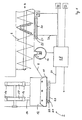
- FIG. 1 shows one of the prior art known Kornelevatorfuß 2 shown by reference exemplified the operation of the invention shall be.
- the grain elevator foot 2 is rotated by a drivable transverse conveyor screw 4 with Schnekkenplanetaryln 6 supplied crop.
- the crop slips via a ramp 8 in the ground segment 10, where it is from the elevator paddles 12, the holding tabs 14 on Conveyor chains 16 are attached to the gears 18 circulating, recorded and promoted.
- Below the Cross auger 4 and at the bottom of the grain elevator foot 2 are each arranged in a housing Moisture sensors 20 attached to the humidity of the over the sensor surface transported away crop determine.
- the sensors 20 are in the embodiment from an electrode 22 and an electronics 24, via lines 26 to the sensor state control device 28 are connected.
- the of the Humidity sensors 20 are determined moisture values from the electronics 24 to the sensor state control device 28 transmitted.
- the sensor state control device 28 asks input or memory elements 34 for certain information from. So can via an input or memory element 34, for example, information about the crop such as corn, wheat, barley, etc., there may be additional information, such as "dry” or “wet” variety, “severely weedy", or telemetrically transmitted information about the calibration or plausibility of the humidity values.
- the driver of the harvester can do so over the Input of the harvested material indirectly the moisture measuring device calibrate to the specific crop.
- FIG 1 is also an additional Moisture measuring device 36 can be seen, which via a line connected to the sensor state control device 28 is.
- the additional moisture measuring device 36 consists of a drainable by a movable piston Measuring chamber, which is rotatably driven in a Housing is stored. After filling the measuring chamber with crop the casing turns in one direction, thus closing the feed opening to the measuring space becomes. During the turn, an associated Humidity sensor determine the humidity value.
- the Measured material can be compressed or weighed in a defined way can be compared to the Humidity sensor 20 measured over a long time become what the accuracy benefits.
- the moisture measuring device 36 can additionally via a heating, for example an infrared drying, dispose of the evaporating amount of water to be able to measure.
- the most accurately determined Moisture value of the additional moisture measuring device 36 may then be from the sensor state control device 28 as the calibration value with that of the humidity sensor 20 compared humidity value and at Deviations a correction factor can be determined.
- the method according to the invention provides the correction value at least partially depending from the working condition of the harvester.
- Working conditions of the harvester can, for example the fruit-dependent attitude, the throughput, the conveying speed, the position of the conveyor organ or the degree of filling of the measuring chamber or the funding body.
Landscapes
- Life Sciences & Earth Sciences (AREA)
- Environmental Sciences (AREA)
- Investigating Or Analyzing Materials By The Use Of Electric Means (AREA)
Description
Die Erfindung bezieht sich auf eine Feuchtemeßeinrichtung sowie ein Verfahren zur Feuchtemessung des Erntegutes in Erntemaschinen.The invention relates to a moisture meter and a method for measuring moisture of the crop in harvesters.
Aus dem Stand der Technik ist es bekannt, Feuchtesensoren in Erntemaschinen einzusetzen, um anhand des Feuchtemeßwertes die Messung der Menge des geernteten Getreides zu präzisieren. Beispielhaft sei hier die DE 41 05 857 genannt. In dieser bekannten Ausführung ist eine Feuchtemeßvorrichtung vorgesehen, die kontinuierlich mit einem Bypass-System die Feuchte des geernteten Erntegutes ermittelt. Ein anderes Beispiel zum Stand der Technik ist in der US 5,616,851 offenbart. Der dort gezeigte Feuchtesensor arbeitet diskontinuierlich, indem eine Menge an Meßgut in einer Meßkammer angesammelt, dann die Messung vorgenommen und das Meßgut wieder in den Erntegutstrom zurückgegeben wird, bevor ein neuer Meßzyklus gestartet werden kann. Auch ist versucht worden, kontinuierlich arbeitende Feuchtesensoren direkt im Förderweg des Erntegutes anzuordnen. Beispielsweise wurde ein Feuchtesensor in einer Komtankbefüllschnecke anstelle eines Schneckenganges oder im Korntank angeordnet. Diese Anbringungsorte der Sensoren wurden gewählt, um unabhängig vom Durchsatz an Erntegut zu sein, da Durchsatzschwankungen durchaus Auswirkungen auf die Genauigkeit des ermittelten Feuchtemeßwertes haben. Da der Sensor in der Befüllschnecke jedoch die Gutförderung unterbricht und der Sensor im Korntank immer nur eine Messung pro Korntank erlaubt, konnten sich beide Systeme nicht am Markt durchsetzen.It is known from the prior art Humidity sensors in harvesting machines to use on the basis of the moisture measurement the measurement of the quantity of the harvested cereals. exemplary here is the DE 41 05 857 called. In this known Execution is a moisture measuring device designed to be continuous with a bypass system determines the moisture of the harvested crop. Another example of the prior art is in US 5,616,851. The humidity sensor shown there works discontinuously by adding a lot Measured material accumulated in a measuring chamber, then the Measurement made and the material to be measured back into the Crop stream is returned before a new one Measuring cycle can be started. Also is tempted been, continuously operating humidity sensors directly to arrange in the conveying path of the crop. For example became a humidity sensor in a tank tank filling screw instead of a helix or arranged in the grain tank. These locations of the Sensors were chosen to be independent of throughput to be harvested, because throughput fluctuations definitely affects the accuracy of the determined Have moisture reading. Because the sensor in the Filling screw, however, the Gutförderung interrupts and the sensor in the grain tank always only one measurement per Grain tank allowed, both systems could not at the Enforce market.
Aus dem Stand der Technik ist weiter aus der DE 196 48 126 ein Mikrowellensensor bekannt, der als Glattsensor ausgebildet ist und auch dazu in der Lage ist, mit den Mikrowellen die Feuchtigkeit des am Glattsensor vorbeibewegten Erntegutes zu ermitteln. Der offenbarte Mikrowellensensor ist relativ teuer und verursacht zudem einen hohen Bauaufwand, da die Umgebung vor den Mikrowellen abgeschirmt werden muß.From the prior art is further from the DE 196 48 126 a microwave sensor known as Smooth sensor is designed and capable of doing so is, with the microwaves the humidity of the am Smooth sensor to determine past moving crop. The disclosed microwave sensor is relatively expensive and also causes a high construction cost, as the Environment shielded from the microwaves got to.
Alle aus dem Stand der Technik bekannten Feuchtesensoren müssen kalibriert werden, um möglichst genaue Feuchtewerte zu erhalten. Dabei ist zwischen einer meßgutsbedingten Kalibrierung, die abhängig ist von der Art des Erntegutes, und der verarbeitungsbedingten Kalibrierung, die beispielsweise von der Meßgutdichte, Fördermenge und Förderorganen bestimmt wird. Für die meßgutbedingte Kalibrierung werden Kalibrierkurven bereitgestellt, die vom Benutzer der Feuchtemeßeinrichtung abgerufen werden können. Diese Kurven sind jeweils für bestimmte Gutttemperaturen gültig. Die Notwendigkeit der verarbeitungsbedingten Kalibrierung wird in der Praxis jedoch umgangen, indem Meßstellen mit zumindest zeitweise konstanten Meßbedingungen eingerichtet werden. Da diese Meßstellen nicht immer konstante Meßbedingungen gewährleisten, ergeben sich hier Fehler, diesich zusätzlich verstärken, wenn weitere verarbeitungsbedingte Fehlerquellen von Messungen, wie beispielsweise die Verschmutzung des Sensors, unberücksichtigt bleiben. Unter solchen Bedingungen hängt die Genauigkeit des Feuchtewertes von der Sorgfalt und dem Verständnis des Bedieners der Erntemaschine für die Belange der Feuchtemeßvorrichtung ab, was jedoch nicht immer vorausgesetzt werden kann.All known from the prior art Humidity sensors need to be calibrated to be as possible to obtain exact humidity values. It is between a calibration-related calibration that depends depends on the type of crop, and the processing Calibration, for example, of the Meßgutdichte, flow rate and conveying organs determined becomes. For the meßgutbedingte calibration Calibration curves provided by the user of the Moisture measuring device can be accessed. These curves are each for specific Gutttemperaturen valid. The need for processing Calibration is bypassed in practice, however by measuring points with at least temporarily constant Measuring conditions are established. This one Measuring points are not always constant measuring conditions ensure that errors arise here, in addition reinforce if more processing related Error sources of measurements, such as the Pollution of the sensor, ignored. Under such conditions, the accuracy of the Humidity value of the care and understanding the operator of the harvester for the concerns of the harvester Moisture meter from, but not always can be assumed.
Es ist die Aufgabe der vorliegenden Erfindung, eine verbesserte Feuchtemeßeinrichtung vorzuschlagen, die die genannten Nachteile der aus dem Stand der Technik bekannten Feuchtemeßeinrichtungen zumindest verringerte.It is the object of the present invention to propose an improved moisture measuring device, the said disadvantages of the state of the art the art known moisture measuring at least decreased.
Die Aufgabe wird durch die Merkmale der Ansprüche 1 und 9 gelöst.The object is achieved by the features of claims 1 and 9 solved.
Die Kombination des Feuchtesensors mit einer Sensorzustandskontrollvorrichtung ermöglicht es, Fehlerzustände bei der Ermittlung des Feuchtesignals zu erkennen und dem Fahrer der Erntemaschine zur Anzeige zu bringen oder Korrekturmaßnahmen einzuleiten beziehungsweise eine Kalibrierung durchzuführen. Auf die bisher erforderlichen Kalibriermaßnahmen kann weitgehend verzichtet werden, da die Sensorzustandskontrollvorrichtung einen guten Teil der Kalbrierarbeiten automatisiert erledigt. Die Zuverlässigkeit der Feuchtemeßvorrichtung wird verbessert und der Fahrer wird von immer wiederkehrenden Routinearbeiten und -kontrollen entlastet. Weitere vorteilhafte Ausgestaltungen der Erfindung ergeben sich aus den kennzeichnenden Merkmalen der Unteransprüche.The combination of the humidity sensor with a Sensor state control device makes it possible Error states in the determination of the humidity signal to recognize and to the driver of the harvester for Display or take corrective action or perform a calibration. On the previously required calibration measures can largely be dispensed with, since the sensor state control device a good part of the Kalbrierarbeiten done automatically. The reliability of Moisture meter is improved and the driver is made of repetitive routine work and controls relieved. Further advantageous embodiments The invention will become apparent from the characterizing Features of the dependent claims.
Die Erfindung wird nachfolgend anhand eines Ausführungsbeispiels näher erläutert. Es zeigt:
- Figur 1:
- einen in einer Prinzipskizze dargestellten Kornelevatorfuß, der mit Feuchtemeßvorrichtungen ausgestattet ist.
- FIG. 1:
- a Kornelevatorfuß shown in a schematic diagram, which is equipped with Moisture measuring devices.
In Figur 1 ist ein aus dem Stand der Technik
bekannter Kornelevatorfuß 2 gezeigt, anhand dessen
beispielhaft die Funktionsweise der Erfindung erläutert
werden soll. Dem Kornelevatorfuß 2 wird von einer rotierend
antreibbaren Querförderschnecke 4 mit Schnekkenwendeln
6 Erntegut zugeführt. Das Erntegut rutscht
über eine Rampe 8 in das Bodensegment 10, wo es von
den Elevatorpaddeln 12, die über Haltelaschen 14 an
Förderketten 16 befestigt sind, die um Zahnräder 18
umlaufen, erfaßt und hochgefördert wird. Unterhalb der
Querföderschnecke 4 und untenseitig am Kornelevatorfuß
2 sind jeweils in einem Gehäuse angeordnete
Feuchtesensoren 20 angebracht, die die Feuchte des
über die Sensorfläche hinweggeförderten Erntegutes
ermitteln. Die Sensoren 20 bestehen im Ausführungsbeispiel
aus einer Elektrode 22 und einer Elektronik 24,
die über Leitungen 26 an die Sensorzustandskontrollvorrichtung
28 angeschlossen sind. Die von den
Feuchtesensoren 20 ermittelten Feuchtewerte werden
von der Elektronik 24 an die Sensorzustandskontrollvorrichtung
28 übermittelt.FIG. 1 shows one of the prior art
known Kornelevatorfuß 2 shown by reference
exemplified the operation of the invention
shall be. The grain elevator foot 2 is rotated by a
drivable transverse conveyor screw 4 with Schnekkenwendeln
6 supplied crop. The crop slips
via a
Die Sensorzustandskontrollvorrichtung 28 besteht
aus Mikroprozessoren sowie einer geeigneten
Auswertesoftware. Sie kann direkt in die Elektronik 24
integriert sein oder sich an anderer Stelle der Erntemaschine
befinden. Zu Erläuterungszwecken ist sie hier
getrennt dargestellt. Die Ermittlung der Feuchtewerte
durch die in Figur 1 dargestellten Feuchtesensoren 20
kann kontinuierlich oder diskontinuierlich erfolgen. Die
Funktion der Sensorzustandskontrollvorrichtung besteht
darin, die vom Feuchtesensor 20 ermittelten Roh-Feuchtewerte
zu korrigieren, indem diese von der Sensorzustandskontrollvorrichtung
mit Kalibriervorgaben
verarbeitetwerden. Dazu ist es erforderlich, daß zusätzliche
Sensoren ihre Sensorwerte an die Sensorzustandskontrollvorrichtung
28 übermitteln. So ist es beispielsweise
möglich, anhand der Werte von anderen
Sensoren die Plausibilität der gemessenen Feuchtewerte
zu überprüfen. So kann die Sensorzustandskontrollvorrichtung
28 beispielsweise über Sensoren 30, die
am Aufnahmeorgan wie beispielsweise einem Schneidwerk,
einem Bearbeitungsorgan wie beispielsweise einem
Dreschwerk, einem Motor, einer Schaltstellung eines
Bedienelementes, einem Lastmesser oder einem
Geschwindigkeitsmesser angebracht sein können, feststellen,
ob die Erntemaschine überhaupt die Ernteorgane
eingeschaltet hat und Erntegut aufnimmt. Stellt die
Sensorzustandskontrollvorrichtung 28 über die Sensorwerte
der Sensoren 30 fest, daß diese Meßbedingungen
nicht vorliegen, so blockiert sie die Zuordnung des
gemessenen Feuchtewertes zu einem Erntegut oder eine
Erntegutmenge oder versieht den Feuchtewert mit
einem Index, der bei der Weiterverarbeitung des Feuchtewertes
verdeutlicht, daß er sich nicht auf die Messung
von Erntegut bezieht. Neben der Auswertung von Sensorsignalen,
die indirekt einen Rückschluß auf die
Meßbedingungen an der Meßstelle zulassen, kann die
Sensorzustandskontrollvorrichtung 28 auch Sensoren
32 abfragen, mit denen unmittelbar der Meßzustand gemessen
werden kann, wie beispielsweise Füllstandsoder
Drucksensoren oder Qualitätssensoren für das
Erntegut, die im Bereich der Meßstelle oder an anderer
Stelle der Erntemaschine angeordnet sind. Die Sensoren
32 können verschiedene Meßstati signalisieren, wie
beispielsweise:
In einer weiteren Ausführung der Erfindung
fragt die Sensorzustandskontrollvorrichtung 28 Eingabe-
oder Speicherelemente 34 auf bestimmte Informationen
ab. So kann über ein Eingabe- oder Speicherelement
34 beispielsweise eine Information über das Erntegut
vorgegeben werden, wie Mais, Weizen, Gerste,
etc., es können Zusatzangaben vorliegen, wie beispielsweise
"trockene" oder "nasse" Sorte, "stark verunkrautet",
oder eine telemetrisch übermittelte Information
über die Kalibrierung oder Plausibiltät der Feuchtewerte.
Der Fahrer der Erntemaschine kann so über die
Eingabe des geernteten Gutes indirekt die Feuchtemeßvorrichtung
auf das spezifische Erntegut kalibrieren.In a further embodiment of the invention
the sensor
In Figur 1 ist außerdem eine zusätzliche
Feuchtemeßvorrichtung 36 zu sehen, die über eine Leitung
mit der Sensorzustandskontrollvorrichtung 28 verbunden
ist. Die zusätzliche Feuchtemeßvorrichtung 36
besteht aus einem von einem beweglichen Kolben entleerbaren
Meßraum, der in einem drehbar angetriebenen
Gehäuse gelagert ist. Nach Füllung des Meßraums
mit Erntegut dreht sich das Gehäuse in eine Richtung,
damit die Zuführöffnung zum Meßraum verschlossen
wird. Während der Umdrehung kann ein zugehöriger
Feuchtesensor den Feuchtewert bestimmen. Das
Meßgut kann definiert verdichtet beziehungsweise verwogen
werden, und das Meßgut kann im Vergleich zum
Feuchtesensor 20 über eine längere Zeit gemessen
werden, was der Genauigkeit zugute kommt. Der
Meßraum kann mit einer zusätzlichen Mahlvorrichtung
ausgestattet sein, damit nicht nur die Oberflächenfeuchte,
sondern die Feuchte des gesamten Erntegutes ermittelbar
ist, um möglichst genau den Meßwert bestimmen
zu können. Die Feuchtemeßvorrichtung 36 kann
zusätzlich über eine Beheizung, beispielsweise eine Infrarottrocknung,
verfügen, um die verdunstende Wassermenge
messen zu können. Der möglichst genau ermittelte
Feuchtewert der zusätzlichen Feuchtemeßvorrichtung
36 kann dann von der Sensorzustandskontrollvorrichtung
28 als Kalibrierwert mit dem vom Feuchtesensor
20 ermittelten Feuchtewert verglichen und bei
Abweichungen ein Korrekturfaktor bestimmt werden.In Figure 1 is also an additional
Das erfindungsgemäße Verfahren sieht vor, den Korrekturwert zumindest teilweise in Abhängigkeit vom Arbeitszustand der Erntemaschine zu bilden. Als Arbeitszustände der Erntemaschine können beispielsweise die fruchtabhängige Einstellung, der Gutdurchsatz, die Fördergeschwindigkeit, die Stellung des Förderorgans oder der Befüllungsgrad des Meßraums beziehungsweise des Förderorgans Berücksichtigung finden.The method according to the invention provides the correction value at least partially depending from the working condition of the harvester. When Working conditions of the harvester can, for example the fruit-dependent attitude, the throughput, the conveying speed, the position of the conveyor organ or the degree of filling of the measuring chamber or the funding body.
Die hier anhand von Förderelementen für einen Mähdrescher erläuterte Erfindung läßt sich von einem Fachmann ohne größeren Aufwand auf andere Erntemaschinen, wie Feldhäcksler, Ballenpressen, Mähwerke, Ladewagen und andere Erntemaschinen übertragen. Auch ist es selbstverständlich, daß die vorgeschlagene Vorrichtung sowie das Verfahren prinzipiell unter Einsatz aller bekannten Sensortechniken für die Feuchtemessung realisiert werden kann. Dabei liegt es im Können eines Durchschnittsfachmanns, für den Anwendungszweck vorteilhafte Änderungen und Ergänzungen vorzunehmen.The here by means of conveying elements for a Combine explained invention can be from a Professional without much effort on others Harvesting machines, such as forage harvesters, balers, Mowers, self-loading wagons and other harvesters transfer. It is also obvious that the proposed Device and the method in principle using all known sensor techniques for the humidity measurement can be realized. It lies it in the skill of an average expert, for the Application advantageous changes and additions make.
Claims (14)
- A moisture measuring apparatus comprising a moisture sensor (20) for measuring moisture in the crop material in a harvester, characterised in that the moisture measuring apparatus is combined with a sensor state monitoring device (28) and wherein additional sensors communicate their measurement values to the sensor state monitoring device (28) and the sensor state monitoring device (28) checks said measurement values with the moisture values communicated by the moisture sensor (20) in relation to each other in respect of plausibility.
- A moisture measuring apparatus according to claim 1 characterised in that additional sensors communicate their measurement values to the sensor state monitoring device (28), they are checked by the sensor state monitoring device (28) with the moisture value communicated by the moisture sensor (20) in relation to each other in respect of plausibility and in the event of implausibilities a correction of the moisture value is automatically triggered off.
- A moisture measuring apparatus according to claim 1 or claim 2 characterised in that additional sensors communicate their measurement values to the sensor state monitoring device (28), they are checked by the sensor state monitoring device (28) with the moisture value communicated by the moisture sensor (20) in relation to each other in respect of plausibility and in the event of implausibilities a display is automatically activated in the driving position.
- A moisture measuring apparatus according to one or more of claims 1 to 3 characterised in that the sensor state monitoring device (28) checks given measurement statuses and automatically triggers a display and/or an action in dependence on the detected measurement status.
- A moisture measuring apparatus according to one or more of claims 1 to 4 characterised in that the sensor state monitoring device (28) is integrated into an electronic system (24).
- A moisture measuring apparatus according to one or more of claims 1 to 5 characterised in that the sensor state monitoring device (28) selects calibration curves governed by the material being measured, on the basis of a selection of the material being measured, which is predetermined by the operator or which is recognised by way of a sensor system.
- A moisture measuring apparatus according to one or more of claims 1 to 6 characterised in that the sensor state monitoring device (28) interrogates input or storage elements (34).
- A moisture measuring apparatus according to one or more of claims 1 to 7 characterised in that the sensor state monitoring device (28) calibrates the moisture values ascertained by the moisture sensors (20) by way of the moisture values of an additional moisture measuring apparatus (36).
- A method of ascertaining a moisture value of crop material with a moisture measuring apparatus in a harvester in which a moisture sensor ascertains a moisture value and communicates same to an electronic evaluation system where same adjusts the moisture value with a calibration-dependent correction value and subjects the adjusted moisture value to further processing for evaluation purposes, characterised in that the correction value is at least partially formed in dependence on the working condition of the harvester and wherein the moisture measuring apparatus is combined with a sensor state monitoring device (28) and wherein additional sensors communicate their measurement values to the sensor state monitoring device (28) and the sensor state monitoring device (28) checks said measurement values with the moisture values communicated by the moisture sensor (20) in relation to each other in respect of plausibility.
- A method according to claim 9 characterised in that the crops-dependent setting of the harvester is taken into consideration as the working condition.
- A method according to claim 9 or claim 10 characterised in that the through-put of material ascertained is taken into consideration as the working condition.
- A method according to one or more of claims 9 to 11 characterised in that the conveyor speed of at least one conveyor element is taken into consideration as the working condition.
- A method according to one or more of claims 9 to 12 characterised in that the position of the conveyor member is taken into consideration as the working condition.
- A method according to one or more of claims 9 to 13 characterised in that the degree of filling of a measurement space or a conveyor element is taken into consideration as the working condition.
Applications Claiming Priority (2)
| Application Number | Priority Date | Filing Date | Title |
|---|---|---|---|
| DE19744483 | 1997-10-09 | ||
| DE19744483A DE19744483A1 (en) | 1997-10-09 | 1997-10-09 | Moisture measuring device and method for moisture measurement in harvesting machines |
Publications (3)
| Publication Number | Publication Date |
|---|---|
| EP0908087A1 EP0908087A1 (en) | 1999-04-14 |
| EP0908087B1 EP0908087B1 (en) | 2002-07-03 |
| EP0908087B2 true EP0908087B2 (en) | 2005-06-01 |
Family
ID=7844965
Family Applications (1)
| Application Number | Title | Priority Date | Filing Date |
|---|---|---|---|
| EP98117586A Expired - Lifetime EP0908087B2 (en) | 1997-10-09 | 1998-09-16 | Method and device for measuring moisture of grain in harvesting machines |
Country Status (3)
| Country | Link |
|---|---|
| EP (1) | EP0908087B2 (en) |
| DE (2) | DE19744483A1 (en) |
| DK (1) | DK0908087T4 (en) |
Families Citing this family (12)
| Publication number | Priority date | Publication date | Assignee | Title |
|---|---|---|---|---|
| GB9811177D0 (en) * | 1998-05-26 | 1998-07-22 | Ford New Holland Nv | Methods for generating field maps |
| DE19959117A1 (en) * | 1999-12-08 | 2001-07-05 | Cord Fiedler | Humidity measuring equipment for bulk material flow has humidity measurement probe arranged to compression region of movable bulk material compression component at one side of cylinder |
| US6686749B2 (en) * | 2001-10-25 | 2004-02-03 | Deere & Company | Multiple frequency grain moisture sensor for combines |
| DE102004048103B4 (en) | 2004-09-30 | 2017-01-12 | Carl Zeiss Spectroscopy Gmbh | Spectrometric measuring head for harvesters and other agricultural machines |
| DE102007053910A1 (en) * | 2007-11-09 | 2009-05-14 | Claas Selbstfahrende Erntemaschinen Gmbh | Agricultural working machine |
| DE102014102789A1 (en) | 2014-03-03 | 2015-09-03 | Claas Selbstfahrende Erntemaschinen Gmbh | Agricultural working machine |
| DE102015102056A1 (en) * | 2015-02-12 | 2016-08-18 | Claas Selbstfahrende Erntemaschinen Gmbh | Method for determining calibration data for a grain loss sensor |
| FR3054313B1 (en) | 2016-07-21 | 2020-09-25 | Renault Trucks Defense | ROUTE CALCULATION METHOD FOR AN ALL-TERRAIN MACHINE |
| DE102018103509B3 (en) * | 2017-10-11 | 2018-12-13 | Carl Zeiss Spectroscopy Gmbh | Mobile ingredient analysis system as well as procedures for sample-correct measurement and user guidance with this |
| DE102021111827A1 (en) | 2021-05-06 | 2022-11-10 | Deere & Company | Sensor arrangement for detecting ingredients |
| DE102023108762A1 (en) * | 2023-04-05 | 2024-10-10 | Claas Selbstfahrende Erntemaschinen Gmbh | sensor arrangement |
| DE102024121764A1 (en) * | 2024-07-31 | 2026-02-19 | Claas Selbstfahrende Erntemaschinen Gmbh | Driver assistance system for an agricultural machine |
Family Cites Families (15)
| Publication number | Priority date | Publication date | Assignee | Title |
|---|---|---|---|---|
| EP0042245B1 (en) * | 1980-06-14 | 1984-11-28 | Claydon Yield-O-Meter Limited | Crop metering device for combine harvesters |
| DE3306460A1 (en) * | 1983-02-24 | 1984-08-30 | Gann Meß- u. Regeltechnik GmbH, 7000 Stuttgart | Electrical humidity meter |
| DE3500839A1 (en) * | 1985-01-12 | 1986-07-17 | Steinecker Elektronik GmbH, 6052 Mühlheim | Measuring instrument for measuring relative humidity |
| FR2643985B1 (en) * | 1989-03-03 | 1991-06-28 | Serdia | APPARATUS FOR CONTINUOUSLY MEASURING THE CONTENT OF A GRANULAR, POWDERY OR VISCOUS PRODUCT |
| US5106339A (en) * | 1990-02-12 | 1992-04-21 | David Manufacturing Company | Moisture monitor system and method for combine harvester |
| US5092819A (en) * | 1990-05-17 | 1992-03-03 | Schroeder Michael J | Method and apparatus for qualitatively measuring characteristics of grain to be harvested |
| DE4105857C2 (en) * | 1991-02-25 | 1994-07-07 | Claas Ohg | Device for measuring a mass flow |
| EP0501099B1 (en) * | 1991-02-25 | 1994-10-26 | Claas Ohg | Mass flow measuring device with a measuring capacitor |
| FR2677764B1 (en) * | 1991-06-13 | 1993-10-15 | Tripette Renaud | HUMIDIMETER FOR GRANULAR OR POWDERY PRODUCTS AND METHOD FOR MEASURING THE MOISTURE RATE. |
| US5343761A (en) * | 1991-06-17 | 1994-09-06 | Allen Myers | Method and apparatus for measuring grain mass flow rate in harvesters |
| DK6996A (en) * | 1995-06-02 | 1996-12-03 | Dronningborg Ind As | Method and apparatus for determining the mass flow of a grain stream |
| CA2182989C (en) * | 1995-09-01 | 2001-03-27 | Frederick William Nelson | Grain moisture sensor |
| US5616851A (en) * | 1995-09-29 | 1997-04-01 | Farmex Inc. | Ex-situ grain moisture analyzer for a combine |
| DE19541167C2 (en) * | 1995-11-04 | 2001-04-05 | Claas Ohg | Device and method for calibrating the measurement of a material flow |
| DE19648126B4 (en) | 1996-11-21 | 2009-01-22 | Claas Kgaa Mbh | Self-propelled forage harvester |
-
1997
- 1997-10-09 DE DE19744483A patent/DE19744483A1/en not_active Withdrawn
-
1998
- 1998-09-16 EP EP98117586A patent/EP0908087B2/en not_active Expired - Lifetime
- 1998-09-16 DE DE59804643T patent/DE59804643D1/en not_active Expired - Lifetime
- 1998-09-16 DK DK98117586T patent/DK0908087T4/en active
Also Published As
| Publication number | Publication date |
|---|---|
| EP0908087A1 (en) | 1999-04-14 |
| DE19744483A1 (en) | 1999-04-15 |
| DE59804643D1 (en) | 2002-08-08 |
| DK0908087T3 (en) | 2002-10-28 |
| DK0908087T4 (en) | 2005-07-04 |
| EP0908087B1 (en) | 2002-07-03 |
Similar Documents
| Publication | Publication Date | Title |
|---|---|---|
| EP0908087B2 (en) | Method and device for measuring moisture of grain in harvesting machines | |
| DE102008017671B4 (en) | Measurement arrangement for mass throughput recording with mass and volume measurement and mass density determination based on this as well as mass throughput specification for small throughputs based on the last mass density recorded | |
| DE19541167C2 (en) | Device and method for calibrating the measurement of a material flow | |
| DE69922847T2 (en) | METHOD OF DATA COLLECTION FOR USE IN HARMONIZATION OF A HARVEST MACHINE AND A DEVICE THEREFOR | |
| CA1165300A (en) | Crop metering device for combine harvesters | |
| EP1344444B1 (en) | Device for detecting the presence of a flow in a harvesting machine | |
| EP2517549B1 (en) | Assembly and method for detecting the quantity of plants on a field | |
| EP1400161A1 (en) | System for measuring the properties of crop material harvested by an agricultural harvester | |
| EP2845461B1 (en) | Assembly for measuring loss in a combine harvester | |
| DE19543343A1 (en) | Agricultural bale press for acquiring, baling and output of crops | |
| EP1266558A2 (en) | Elevator conveyor with force sensor for detecting the throughput of a combine | |
| DE102015215299A1 (en) | Measuring device for examining harvested grain in a combine harvester | |
| US6389884B1 (en) | Device and method for measuring the moisture of crop material in agricultural machines | |
| EP2389061A1 (en) | Device and method for determining the mass-related yield of grains in harvesting machines | |
| EP1243174A1 (en) | Combine with humidity sensor | |
| DE19523026A1 (en) | Mass flow measurement for grain e.g. on combine harvester | |
| EP4442102A1 (en) | Method and arrangement for the computer-assisted processing of an electronic yield map | |
| EP3459337B1 (en) | Agricultural machine | |
| DE3726930C2 (en) | ||
| DE19618042A1 (en) | Combine harvester with throughput performance measurement | |
| EP1518452A1 (en) | Weighing system on an agricultural machine | |
| EP2524584B1 (en) | Agricultural device | |
| DE102023126147A1 (en) | Sensor assembly, agricultural machine and associated process | |
| DE19744481A1 (en) | Unit for measuring moisture of harvested material | |
| DE102023134642A1 (en) | Mower |
Legal Events
| Date | Code | Title | Description |
|---|---|---|---|
| PUAI | Public reference made under article 153(3) epc to a published international application that has entered the european phase |
Free format text: ORIGINAL CODE: 0009012 |
|
| AK | Designated contracting states |
Kind code of ref document: A1 Designated state(s): BE DE DK FR GB IT |
|
| AX | Request for extension of the european patent |
Free format text: AL;LT;LV;MK;RO;SI |
|
| 17P | Request for examination filed |
Effective date: 19991014 |
|
| AKX | Designation fees paid |
Free format text: BE DE DK FR GB IT |
|
| GRAG | Despatch of communication of intention to grant |
Free format text: ORIGINAL CODE: EPIDOS AGRA |
|
| GRAG | Despatch of communication of intention to grant |
Free format text: ORIGINAL CODE: EPIDOS AGRA |
|
| GRAH | Despatch of communication of intention to grant a patent |
Free format text: ORIGINAL CODE: EPIDOS IGRA |
|
| 17Q | First examination report despatched |
Effective date: 20011210 |
|
| GRAH | Despatch of communication of intention to grant a patent |
Free format text: ORIGINAL CODE: EPIDOS IGRA |
|
| GRAA | (expected) grant |
Free format text: ORIGINAL CODE: 0009210 |
|
| AK | Designated contracting states |
Kind code of ref document: B1 Designated state(s): BE DE DK FR GB IT |
|
| PG25 | Lapsed in a contracting state [announced via postgrant information from national office to epo] |
Ref country code: IT Free format text: LAPSE BECAUSE OF FAILURE TO SUBMIT A TRANSLATION OF THE DESCRIPTION OR TO PAY THE FEE WITHIN THE PRESCRIBED TIME-LIMIT;WARNING: LAPSES OF ITALIAN PATENTS WITH EFFECTIVE DATE BEFORE 2007 MAY HAVE OCCURRED AT ANY TIME BEFORE 2007. THE CORRECT EFFECTIVE DATE MAY BE DIFFERENT FROM THE ONE RECORDED. Effective date: 20020703 |
|
| REF | Corresponds to: |
Ref document number: 59804643 Country of ref document: DE Date of ref document: 20020808 |
|
| GBT | Gb: translation of ep patent filed (gb section 77(6)(a)/1977) |
Effective date: 20020813 |
|
| REG | Reference to a national code |
Ref country code: DK Ref legal event code: T3 |
|
| ET | Fr: translation filed | ||
| PLBQ | Unpublished change to opponent data |
Free format text: ORIGINAL CODE: EPIDOS OPPO |
|
| PLBI | Opposition filed |
Free format text: ORIGINAL CODE: 0009260 |
|
| PLBF | Reply of patent proprietor to notice(s) of opposition |
Free format text: ORIGINAL CODE: EPIDOS OBSO |
|
| 26 | Opposition filed |
Opponent name: DEERE & COMPANY Effective date: 20030328 |
|
| PLBB | Reply of patent proprietor to notice(s) of opposition received |
Free format text: ORIGINAL CODE: EPIDOSNOBS3 |
|
| PUAH | Patent maintained in amended form |
Free format text: ORIGINAL CODE: 0009272 |
|
| STAA | Information on the status of an ep patent application or granted ep patent |
Free format text: STATUS: PATENT MAINTAINED AS AMENDED |
|
| 27A | Patent maintained in amended form |
Effective date: 20050601 |
|
| AK | Designated contracting states |
Kind code of ref document: B2 Designated state(s): BE DE DK FR GB IT |
|
| REG | Reference to a national code |
Ref country code: DK Ref legal event code: T4 |
|
| GBTA | Gb: translation of amended ep patent filed (gb section 77(6)(b)/1977) | ||
| ET3 | Fr: translation filed ** decision concerning opposition | ||
| PGFP | Annual fee paid to national office [announced via postgrant information from national office to epo] |
Ref country code: DK Payment date: 20060925 Year of fee payment: 9 |
|
| REG | Reference to a national code |
Ref country code: DK Ref legal event code: EBP |
|
| PG25 | Lapsed in a contracting state [announced via postgrant information from national office to epo] |
Ref country code: DK Free format text: LAPSE BECAUSE OF NON-PAYMENT OF DUE FEES Effective date: 20071001 |
|
| REG | Reference to a national code |
Ref country code: FR Ref legal event code: PLFP Year of fee payment: 18 |
|
| PGFP | Annual fee paid to national office [announced via postgrant information from national office to epo] |
Ref country code: GB Payment date: 20150922 Year of fee payment: 18 Ref country code: DE Payment date: 20150624 Year of fee payment: 18 |
|
| PGFP | Annual fee paid to national office [announced via postgrant information from national office to epo] |
Ref country code: BE Payment date: 20150921 Year of fee payment: 18 Ref country code: FR Payment date: 20150923 Year of fee payment: 18 |
|
| PG25 | Lapsed in a contracting state [announced via postgrant information from national office to epo] |
Ref country code: BE Free format text: LAPSE BECAUSE OF NON-PAYMENT OF DUE FEES Effective date: 20160930 |
|
| REG | Reference to a national code |
Ref country code: DE Ref legal event code: R119 Ref document number: 59804643 Country of ref document: DE |
|
| GBPC | Gb: european patent ceased through non-payment of renewal fee |
Effective date: 20160916 |
|
| REG | Reference to a national code |
Ref country code: FR Ref legal event code: ST Effective date: 20170531 |
|
| PG25 | Lapsed in a contracting state [announced via postgrant information from national office to epo] |
Ref country code: FR Free format text: LAPSE BECAUSE OF NON-PAYMENT OF DUE FEES Effective date: 20160930 Ref country code: GB Free format text: LAPSE BECAUSE OF NON-PAYMENT OF DUE FEES Effective date: 20160916 Ref country code: DE Free format text: LAPSE BECAUSE OF NON-PAYMENT OF DUE FEES Effective date: 20170401 |
|
| REG | Reference to a national code |
Ref country code: BE Ref legal event code: MM Effective date: 20160930 |