EP0908071B1 - Process for controlling the establishment and operation of paths of transmission (bearers) in a wireless telecommunication system, in particular in a dect-specific rll/wll-system bound into an isdn-system as a local information transmission loop - Google Patents
Process for controlling the establishment and operation of paths of transmission (bearers) in a wireless telecommunication system, in particular in a dect-specific rll/wll-system bound into an isdn-system as a local information transmission loop Download PDFInfo
- Publication number
- EP0908071B1 EP0908071B1 EP97930303A EP97930303A EP0908071B1 EP 0908071 B1 EP0908071 B1 EP 0908071B1 EP 97930303 A EP97930303 A EP 97930303A EP 97930303 A EP97930303 A EP 97930303A EP 0908071 B1 EP0908071 B1 EP 0908071B1
- Authority
- EP
- European Patent Office
- Prior art keywords
- transmission
- transmission path
- channel
- dect
- paths
- Prior art date
- Legal status (The legal status is an assumption and is not a legal conclusion. Google has not performed a legal analysis and makes no representation as to the accuracy of the status listed.)
- Expired - Lifetime
Links
- 230000005540 biological transmission Effects 0.000 title claims abstract description 135
- 238000000034 method Methods 0.000 title claims description 24
- 101000946124 Homo sapiens Lipocalin-1 Proteins 0.000 claims description 14
- 102100034724 Lipocalin-1 Human genes 0.000 claims description 14
- 101001023833 Homo sapiens Neutrophil gelatinase-associated lipocalin Proteins 0.000 claims description 13
- 102100035405 Neutrophil gelatinase-associated lipocalin Human genes 0.000 claims description 13
- 238000004891 communication Methods 0.000 description 7
- 230000011664 signaling Effects 0.000 description 4
- 238000012545 processing Methods 0.000 description 3
- 238000010586 diagram Methods 0.000 description 2
- 239000008186 active pharmaceutical agent Substances 0.000 description 1
- 238000010276 construction Methods 0.000 description 1
- 238000011161 development Methods 0.000 description 1
- 230000018109 developmental process Effects 0.000 description 1
- 238000005516 engineering process Methods 0.000 description 1
- 230000010354 integration Effects 0.000 description 1
- 238000012552 review Methods 0.000 description 1
- 238000004088 simulation Methods 0.000 description 1
- 238000012546 transfer Methods 0.000 description 1
Images


Classifications
-
- H—ELECTRICITY
- H04—ELECTRIC COMMUNICATION TECHNIQUE
- H04W—WIRELESS COMMUNICATION NETWORKS
- H04W28/00—Network traffic management; Network resource management
- H04W28/16—Central resource management; Negotiation of resources or communication parameters, e.g. negotiating bandwidth or QoS [Quality of Service]
- H04W28/26—Resource reservation
-
- H—ELECTRICITY
- H04—ELECTRIC COMMUNICATION TECHNIQUE
- H04W—WIRELESS COMMUNICATION NETWORKS
- H04W84/00—Network topologies
- H04W84/02—Hierarchically pre-organised networks, e.g. paging networks, cellular networks, WLAN [Wireless Local Area Network] or WLL [Wireless Local Loop]
- H04W84/10—Small scale networks; Flat hierarchical networks
- H04W84/14—WLL [Wireless Local Loop]; RLL [Radio Local Loop]
Definitions
- the invention relates to a method for controlling the construction of transmission paths (bearers) in wireless telecommunication systems, in particular in a DECT-specific RLL / WLL system (radio local.) Integrated as a local message transmission loop in an ISDN system L oop / W ireless L ocal L oop) - according to the preamble of claim 1.
- FIGURE 1 shows, starting from the publications "Kommunikationstechnik Electronics, Berlin 45 (1995) Issue 1, Pages 21 to 23 and Issue 3 Pages 29 and 30" and IEE Colloquium 1993, 173; (1993), pp. 29/1 - 29/7 ; W. Hing, F.
- Halsall "Cordless access to the ISDN basic rate service" on the basis of a D ECT / I SDN I ntermediate S ystem DIIS according to ETSI publication prETS 300xxx, Version 1.10 September 1996 "I SDN ⁇ D ECT specific R LL / LL W "- T elekommunikations s ystem IDRW-TS (Integrated Services Digital Network ⁇ R adio in the L ocal L oop / W ireless in the L ocal L oop) with an ISDN telecommunications t ecause s ystem I-TTS [compare.
- the DECT / ISDN intermediate system DIIS or the RLL / WLL telecommunication subsystem RW-TTS is based preferably on a D ECT / G AP S ystem DGS [D igital E nhanced (formerly E uropean) Cordless Telecommunication; see. (1): Communications Engineering Electronics 42 (1992) Jan./Feb. No. 1, Berlin, DE; U. Pilger "Structure of the DECT standard", pages 23 to 29 in connection with the ETSI publication ETS 300175-1 ... 9, October 1992; (2): Telcom Report 16 (1993), No.
- the DECT / ISDN Intermediate System DIIS or the RLL / WLL telecommunications subsystem RW-TTS can alternatively also be based on a GSM system ( G roupe S fugciale M obile or G lobal S ystem for M obile Communication; cf. 1991) June, No. 3, Berlin, DE; A.Mann: "The GSM standard - basis for digital European mobile radio networks", pages 137 to 152).
- GSM G roupe S fuge M obile or G lobal S ystem for M obile Communication; cf. 1991
- radio channels e.g. DECT channels
- the wireless connection technology RLL / WLL R adio in the L ocal L oop / W ireless in the L ocal L oop
- the ISDN subscriber ISDN services are made available on standard ISDN interfaces (see FIGURE 1).
- IDRW-TS "ISDN ⁇ RLL / WLL DECT-specific" of FIGURE 1 is a telecommunication subscriber (user) TCU (T ele- C ommunication U ser) ndpoint with his terminal TE (T erminal E; T erminal E quipment ) z. B.
- S-BUS S-interface
- RLL / WLL telecommunications subsystem RW-TTS - DECT / ISDN Intermediate System DIIS first telecommunications subsystem
- S-BUS S-BUS
- network termination NT N etwork T ermination
- I-TTS second telecommunication subsystem
- the first telecommunication subsystem DIIS consists essentially of two telecommunications interfaces, a first telecommunications interface DIFS (D ECT I ntermediate F ixed S ystem) and a second telecommunications interface DIPS (D ECT I ntermediate P ortable S ystem) that wirelessly, for example via a DECT air interface , are connected. Because of the quasi-localized first telecommunication interface DIFS, the first telecommunication subsystem DIFS forms the local message transmission loop defined above in this context.
- the first telecommunication interface DIFS a radio fixed part RFP (R adio F ixed P art), an interworking unit IWU 1 (I nter W orking U nit) and an interface circuit INC1 (IN terface C ircuitry) to the S-interface.
- the second telecommunication interface DIPS contains a radio portable part RPP (R adio P ortable P art) and an interworking unit IWU 2 (I nter W orking U nit) and an interface circuit INC2 (IN terface C ircuitry) to the S-interface.
- the RFP fixed part and the RPP radio handset form the well-known DECT / GAP system DGS.
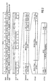
- FIGURE 2 shows, based on the publication "communications engineering Elektronik 42 (1992) Jan./Feb., No. 1, Berlin, DE; U. Pilger: "Structure of the DECT standard", pages 23 to 29 in Connection with ETS 300 175-1 ... October 9, 1992 "the TDMA structure of the DECT / GAP system DGS.
- the DECT / GAP system is a hybrid system with regard to multiple access methods, in accordance with the FDMA principle on ten frequencies in the frequency band between 1.88 and 1.90 GHz radio messages after the TDMA principle according to FIG 2 in a predetermined time Sequence from the base station RFP to the handset RPP and from Handset RPP sent to the base station RFP (duplex operation) can be.
- the time sequence is one Multi-time frame MZR determined that occurs every 160 ms and the 16 time frames ZR, each with a duration of 10 ms having.
- this time frame ZR will be by base station RFP and handset RPP transmit information separately relate to a C, M, N, P, Q channel defined in the DECT standard. Will ZR information for several in a timeframe transmit these channels, the transmission takes place according to a priority list with M> C> N and P> N.
- time slots ZS time slots 12 ... 23
- time slots 12 ... 23 time slots 12 ... 23
- time slots 12 ... 23 time slots 12 ... 23
- ZS is information with a bit length according to the DECT standard transferred from 480 bits. 32 of these 480 bits become 32 Bit as synchronization information in a SYNC field and 388 bits transmitted as useful information in a D field. The remaining 60 bits are used as additional information in a Z field and as protection information in a "Guard-Time" field transfer.
- the 388 bits transmitted as user information of the D field are subdivided into a 64 bit long A field, a 320 bit long B field and a 4 bit long "X-CRC" word.
- the 64 bit long A field consists of an 8 bit long data header with a 40 bit data record Data for the C, Q, M, N, P channels and a 16 bit long "A-CRC" word together.
- FIG. 3 shows on the basis of the OSI / ISO layer model [cf. (1): confirmsability - Irish Weg Fix Jg. 48, 2/1995, pages 102 to 111; (2): ETSI publication ETS 300175-1.9, October 1992; (3) : ETSI publication ETS 300102, February 1992; (4): ETSI publication ETS 300125, September 1991; ( 5): ETSI publication ETS 300012, April 1992] a model of the C level of the "ISDN ⁇ DECT-specific RLL / WLL" telecommunications system IDRW-TS according to FIGURE 1.
- FIG. 4 shows on the basis of the OSI / ISO layer model [cf. (1): confirmsability - Irish Weglim Jg. 48, 2/1995, pages 102 to 111; (2): ETSI publication ETS 300175-1.9, October 1992; (3) : ETSI publication ETS 300102, February 1992; (4): ETSI publication ETS 300125, September 1991; (5) : ETSI publication ETS 300012, April 1992] a U-level model for voice data transmission of the "ISDN ⁇ DECT-specific RLL / WLL" telecommunication system IDRW-TS according to FIG. 1.
- the C s channel structure offers an optimal bandwidth economy for a standard voice connection, since according to FIGURE 5 starting from FIGURES 3 and 4 and taking into account the ETSI publications (ETS 300175-1, 10/1992, Chapter 7; ETS 300175 -3, 10/1992, chapter 4.1; ETS 300175-4, 10/1992, chapter 4) only one transmission path (bearer) - e.g. MBC with the LCNy, LCN1 according to FIGURE 5 - or a connection or a time slot is required becomes.
- ETSI publications ETS 300175-1, 10/1992, Chapter 7; ETS 300175 -3, 10/1992, chapter 4.1; ETS 300175-4, 10/1992, chapter 4
- only one transmission path (bearer) - e.g. MBC with the LCNy, LCN1 according to FIGURE 5 - or a connection or a time slot is required becomes.
- the use of the C f channel leads from FIGURES 3 and 4 and taking into account the ETSI publications (ETS 300175-1, 10/1992, chapter 7; ETS 300175-3, 10/1992, chapter 4.1 ; ETS 300175-4, 10/1992, Chapter 4) to a lower bandwidth economy, since the U-plane (U-plane) itself requires a further transmission path (bearer) or a further connection or a further time slot; ie two transmission paths (bearer) - for example MBC with the LCN2, LCNz and MBC with the LCNy, LCN1 according to FIGURE 5 - or two connections or two time slots are required for a simple voice connection.
- ETSI publications ETS 300175-1, 10/1992, chapter 7
- ETS 300175-3, 10/1992, chapter 4.1 ETS 300175-4, 10/1992, Chapter 4
- ETS 300175-4 10/1992, Chapter 4
- the U-plane itself requires a further transmission path (bearer)
- three transmission paths e.g. MBC with the LCNx, LCN0, MBC with the LCNy, LCN1 and MBC with the LCNz, LCN2 according to FIGURE 5 - or three connection or three time slots required.
- the object underlying the invention is in wireless telecommunications systems, especially in one as a local message transmission loop in an ISDN system integrated DECT-specific RLL / WLL system, the Structure and use of transmission paths regarding the Number of transmission paths for wireless message transmission to optimize.
- This task is based on that in the preamble of Claim 1 defined method by the in the Characteristic of claim 1 specified features solved.
- the idea underlying the invention is that Structure and use of transmission paths (bearer) between Radio transmitters / receivers in wireless telecommunication systems of the aforementioned and outlined Art by assigning transmission route numbers to the To control transmission paths so that a collision when building and the use of the transmission paths (connections) avoided and at the same time the resources of the air interface be used efficiently. This will reduce the effort in the telecommunications systems and the susceptibility to errors minimized when establishing a connection (establishment of transmission paths).
- a first embodiment of the invention is based on the FIGURES 6 and 7 explained.
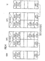
- FIGURE 6 shows an incentive state diagram of how a change of channel from the C f channel to the C s channel can be achieved by controlling the transmission path numbers with minimal expenditure on transmission paths (saving resources of the air interface).
- the first telecommunication interface DIFS (radio transceiver) is connected on a first transmission path with a first transmission path number LCNx (Logical Connection Number; identifier) through the first transmission channel C f to the second telecommunication interface DIPS (radio transceiver).
- LCNx Logical Connection Number; identifier
- the first telecommunication interface DIFS requests the U level at the second telecommunication interface DIPS on.
- FIGURE 7 shows another incentive state diagram, such as by controlling the transmission path numbers one from the second Telecommunications interface DIPS (radio transceiver) desired channel change of the first Telecommunication interface DIFS (radio transmission / reception device) can be signaled and this then initiates the channel change and together with the second Telecommunications interface performs DIPS.
- DIPS radio transceiver
- DIFS radio transmission / reception device
- the second transmission channel C s is used for message transmission on the C level.
- the U level is also used.
- a transmission path with a transmission path number LCN (identifier) for using the first transmission channel C f has not yet been set up.
- the second transmission channel C s has a smaller transmission capacity than the first transmission channel C f .
- the second telecommunication interface DIPS recognizes that the first transmission channel C f is necessary. However, since there is still no transmission path with the identifier LCN, for example the identifier LCN0, for the first transmission channel C f , this is set up by it.
- the choice of the identifier LCN - in the present case the LCN0 - as The transmission path to be set up is not identified arbitrary, but again specifically according to a given one Selection criterion.
- This criterion is very general formulates that as the identifier LCN the identifier of the possible Identifiers LCN0, LCN1, LCN2 is still used is not used for another transmission path, so free is.
- selection criterion Is an alternative to the selection criterion mentioned above it is also possible to have special characteristics of the selection criterion to be used for the identification assignment. For example, - like in present case - always the smallest free identifier of the identifiers LCN0, LCN1, LCN2 or the largest free identifier of the Identifiers LCN0, LCN1, LCN2 can be used.
- the second telecommunications interface sends for the establishment of the transmission path DIPS according to the ETSI publication ETS 300175-3, October 1992, chap. 10.5.1.2 and 10.5.1.3 preferably for the establishment of a transmission path is responsible for the first telecommunications interface DIFS a DECT-specific first B-field message "BEARER_REQUEST" (cf. ETSI publication ETS 300175-3, October 1992, chap. 7.3.3.2) as a command (COMMAND).
- the first telecommunication interface DIFS then sends a DECT-specific after receiving the first B-field message second B-field message "BEARER_CONFIRM" (cf. ETSI publication ETS 300175-3, October 1992, chap. 7.3.3.3) in response (RESPONSE) to the second telecommunications interface DIPS.
- BEARER_CONFIRM cf. ETSI publication ETS 300175-3, October 1992, chap. 7.3.3.3
- the second telecommunications interface DIPS confirms the first MAC message "ATTRIBUTES_T._REQUEST” by sending the second MAC message "ATTRIBUTES_T._CONFIRM" to the first telecommunications interface DIFS.
- the first transmission channel C f is then used for message transmission at the C level.
Landscapes
- Engineering & Computer Science (AREA)
- Quality & Reliability (AREA)
- Computer Networks & Wireless Communication (AREA)
- Signal Processing (AREA)
- Mobile Radio Communication Systems (AREA)
- Data Exchanges In Wide-Area Networks (AREA)
- Small-Scale Networks (AREA)
Abstract
Description
In Nachrichtensystemen mit einer Nachrichtenübertragungsstrecke
zwischen einer Nachrichtenquelle und einer Nachrichtensenke
werden zur Nachrichtenverarbeitung und -übertragung
Sende- und Empfangsgeräte verwendet, bei denen
und/oder CDMA (Code Division Multiple Access) - z.B. nach Funkstandards wie DECT, GSM, WACS oder PACS, IS-54, PHS, PDC etc. [vgl. IEEE Communications Magazine, January 1995, Seiten 50 bis 57; D.D. Falconer et al:"Time Division Multiple Access Methods for Wireless Personal Communications"] drahtlos erfolgt.
and / or CDMA (code Division Multiple A ccess) - for example by radio standards such as DECT, GSM, WACS or PACS, IS-54, PHS, PDC etc. [cp. IEEE Communications Magazine, January 1995, pages 50 to 57; DD Falconer et al: "Time Division Multiple Access Methods for Wireless Personal Communications"].
"Nachricht" ist ein übergeordneter Begriff, der sowohl für
den Sinngehalt (Information) als auch für die physikalische
Repräsentation (Signal) steht. Trotz des gleichen Sinngehaltes
einer Nachricht - also gleicher Information - können unterschiedliche
Signalformen auftreten. So kann z. B. eine einen
Gegenstand betreffende Nachricht
Ausgehend von dieser allgemeinen Definition eines Nachrichtensystems
bezieht sich die Erfindung auf ein Verfahren zum
Steuern des Aufbaus von Übertragungswegen (Bearer) in drahtlosen
Telekommunikationssystemen, insbesondere in einem als
lokale Nachrichtenübertragungsschleife in einem ISDN-System
eingebundenen DECT-spezifischen RLL/WLL-System (Radio Local
Loop/Wireless Local Loop) - gemäß dem Oberbegriff des Patentanspruches
1.Based on this general definition of a message system, the invention relates to a method for controlling the construction of transmission paths (bearers) in wireless telecommunication systems, in particular in a DECT-specific RLL / WLL system (radio local.) Integrated as a local message transmission loop in an ISDN system L oop / W ireless L ocal L oop) - according to the preamble of
FIGUR 1 zeigt ausgehend von den Druckschriften "Nachrichtentechnik
Elektronik, Berlin 45 (1995) Heft 1, Seiten 21 bis 23
und Heft 3 Seiten 29 und 30" sowie IEE Colloquium 1993, 173;
(1993), Seiten 29/1 - 29/7; W. Hing, F. Halsall:"Cordless access
to the ISDN basic rate service" auf der Basis eines
DECT/ISDN Intermediate Systems DIIS gemäß der ETSI-Publikation
prETS 300xxx, Version 1.10, September 1996 ein "ISDN
↔ DECT-spezifisches RLL/WLL"-Telekommunikationssystem IDRW-TS(Integrated
Services Digital Network ↔ Radio in the Local
Loop/Wireless in the Local Loop) mit einem ISDN-Telekommunikationsteilsystem
I-TTS [vgl. Druckschrift "Nachrichtentechnik
Elektronik, Berlin 41-43, Teil: 1 bis 10, T 1: (1991) Heft
3, Seiten 99 bis 102; T 2: (1991) Heft 4, Seiten 138 bis 143;
T 3: (1991) Heft 5, Seiten 179 bis 182 und Heft 6, Seiten 219
bis 220; T4: (1991) Heft 6, Seiten 220 bis 222 und (1992)
Heft 1, Seiten 19 bis 20; T 5: (1992) Heft 2, Seiten 59 bis 62
und (1992) Heft 3, Seiten 99 bis 102; T 6: (1992) Heft 4, Seiten
150 bis 153; T 7: (1992) Heft 6, Seiten 238 bis 241; T 8:
(1993) Heft 1, Seiten 29 bis 33; T9: (1993) Heft 2, Seiten 95
bis 97 und (1993) Heft 3, Seiten 129 bis 135; T 10: (1993)
Heft 4, Seiten 187 bis 190;"] und einem DECT-spezifischen
RLL/WLL-Telekommunikationsteilsystem RW-TTS.FIGURE 1 shows, starting from the publications "Kommunikationstechnik Electronics, Berlin 45 (1995)
Das DECT/ISDN Intermediate System DIIS bzw. das RLL/WLL-Telekommunikationsteilsystem
RW-TTS basiert dabei vorzugsweise
auf ein DECT/GAP-System DGS [Digital Enhanced (früher:
European) Cordless Telecommunication; vgl. (1): Nachrichtentechnik
Elektronik 42 (1992) Jan./Feb. Nr. 1, Berlin, DE; U.
Pilger "Struktur des DECT-Standards", Seiten 23 bis 29 in
Verbindung mit der ETSI-Publikation ETS 300175-1...9, Okt.
1992; (2): Telcom Report 16 (1993), Nr. 1, J. H. Koch:
"Digitaler Komfort für schnurlose Telekommunikation - DECT-Standard
eröffnet neue Nutzungsgebiete", Seiten 26 und 27;
(3): tec 2/93 - Das technische Magazin von Ascom "Wege zur
universellen mobilen Telekommunikation", Seiten 35 bis 42;
(4): Philips Telecommunication Review Vol. 49, No. 3, Sept.
1991, R.J. Mulder:" DECT, a universal cordless access system";
(5): WO 93/21719 (FIG 1 bis 3 mit dazugehöriger Beschreibung)].
Der GAP-Standard (Generic Access Profile) ist
eine Untermenge des DECT-Standards, dem die Aufgabe zukommt,
die Interoperabilität der DECT-Luftschnittstelle für Telefonanwendungen
sicherzustellen (vgl. ETSI-Publikation prETS
300444, April 1995). The DECT / ISDN intermediate system DIIS or the RLL / WLL telecommunication subsystem RW-TTS is based preferably on a D ECT / G AP S ystem DGS [D igital E nhanced (formerly E uropean) Cordless Telecommunication; see. (1): Communications Engineering Electronics 42 (1992) Jan./Feb. No. 1, Berlin, DE; U. Pilger "Structure of the DECT standard",
Das DECT/ISDN Intermediate System DIIS bzw. das RLL/WLL-Telekommunikationsteilsystem RW-TTS kann alternativ auch auf einem GSM-System basieren (Groupe Spéciale Mobile oder Global System for Mobile Communication; vgl. Informatik Spektrum 14 (1991) Juni, Nr. 3, Berlin, DE; A.Mann:"Der GSM-Standard - Grundlage für digitale europäische Mobilfunknetze", Seiten 137 bis 152). Stattdessen ist es im Rahmen eines hybriden Telekommunikationssystems auch möglich, daß das ISDN-Telekommunikationsteilsystem I-TTS als GSM-System ausgebildet ist.The DECT / ISDN Intermediate System DIIS or the RLL / WLL telecommunications subsystem RW-TTS can alternatively also be based on a GSM system ( G roupe S péciale M obile or G lobal S ystem for M obile Communication; cf. 1991) June, No. 3, Berlin, DE; A.Mann: "The GSM standard - basis for digital European mobile radio networks", pages 137 to 152). Instead, it is also possible in the context of a hybrid telecommunications system for the ISDN telecommunications subsystem I-TTS to be designed as a GSM system.
Darüber hinaus kommen als weitere Möglichkeiten für die Realisierung des DECT/ISDN Intermediate System DIIS bzw. des RLL/WLL-Telekommunikationsteilsystems RW-TTS oder des ISDN-Telekommunikationsteilsystems I-TTS die eingangs erwähnten Systeme sowie zukünftige Systeme in Frage, die auf die bekannten Vielfachzugriffsmethoden FDMA, TDMA, CDMA (Frequency Division Multiple Access, Time Division Multiple Access, Code Division Multiple Access) und hieraus gebildete hybride Vielfachzugriffsmethoden basieren.In addition, the systems mentioned at the outset as well as future systems which are based on the known multiple access methods are possible as further options for the implementation of the DECT / ISDN Intermediate System DIIS or the RLL / WLL telecommunications subsystem RW-TTS or the ISDN telecommunications subsystem I-TTS FDMA, TDMA, CDMA ( F requency D ivision M ultiple A ccess, T ime D ivision M ultiple A ccess, C ode D ivision M ultiple A ccess) and hybrid multiple access methods formed from them.
Die Verwendung von Funkkanälen (z.B. DECT-Kanälen) in klassischen leitungsgebundenen Telekommunikationssystemen, wie dem ISDN, gewinnt zunehmend an Bedeutung, insbesondere vor dem Hintergrund zukünftiger alternativer Netzbetreiber ohne eigenes komplettes Drahtnetz.The use of radio channels (e.g. DECT channels) in classic wired telecommunications systems such as the ISDN is becoming increasingly important, especially before Background of future alternative network operators without their own complete wire mesh.
So sollen z. B. bei dem RLL/WLL-Telekommunikationsteilsystem RW-TTS die drahtlose Anschlußtechnik RLL/WLL (Radio in the Local Loop/Wireless in the Local Loop) z.B. unter der Einbindung des DECT-Systems DS dem ISDN-Teilnehmer ISDN-Dienste an Standard-ISDN-Schnittstellen verfügbar gemacht werden (vgl. FIGUR 1).So z. B. in the RLL / WLL telecommunications subsystem RW-TTS, the wireless connection technology RLL / WLL ( R adio in the L ocal L oop / W ireless in the L ocal L oop), for example with the integration of the DECT system DS, the ISDN subscriber ISDN services are made available on standard ISDN interfaces (see FIGURE 1).
In dem "ISDN ↔ DECT-spezifischen RLL/WLL"-Telekommunikationssystem IDRW-TS nach FIGUR 1 ist ein Telekommunikationsteilnehmer (Benutzer) TCU (Tele-Communication User) mit seinem Endgerät TE (Terminal Endpoint; Terminal Equipment) z. B. über eine standardisierte S-Schnittstelle (S-BUS), das als lokale Nachrichtenübertragungsschleife ausgebildete - vorzugsweise DECT-spezifische und in dem RLL/WLL-Telekommunikationsteilsystem RW-TTS enthaltene - DECT/ISDN Intermediate System DIIS (erstes Telekommunikationsteilsystem), eine weitere standardisierte S-Schnittstelle (S-BUS), einen Netzabschluß NT (Network Termination) und eine standardisierte U-Schnittstelle des ISDN-Telekommunikationsteilystems) I-TTS (zweites Telekommunikationsteilsystem) in die ISDN-Welt mit den darin verfügbaren Diensten eingebunden.In the telecommunication system IDRW-TS "ISDN ↔ RLL / WLL DECT-specific" of FIGURE 1 is a telecommunication subscriber (user) TCU (T ele- C ommunication U ser) ndpoint with his terminal TE (T erminal E; T erminal E quipment ) z. B. via a standardized S-interface (S-BUS), which is designed as a local message transmission loop - preferably DECT-specific and contained in the RLL / WLL telecommunications subsystem RW-TTS - DECT / ISDN Intermediate System DIIS (first telecommunications subsystem), another standardized S interface (S-BUS), a network termination NT (N etwork T ermination) and a standardized U interface of the ISDN Telekommunikationsteilystems) I-TTS (second telecommunication subsystem) involved in the ISDN world and their available services.
Das erste Telekommunikationsteilsystem DIIS besteht im wesentlichen aus zwei Telekommunikationsschnittstellen, einer ersten Telekommunikationsschnittstelle DIFS (DECT Intermediate Fixed System) und einer zweiten Telekommunikationsschnittstelle DIPS (DECT Intermediate Portable System), die drahtlos, z.B. über eine DECT-Luftschnittstelle, miteinander verbunden sind. Wegen der quasi-ortsgebundenen ersten Telekommunikationsschnittstelle DIFS bildet das erste Telekommunikationsteilsystem DIFS die vorstehend in diesem Zusammenhang definierte lokale Nachrichtenübertragungsschleife. Die erste Telekommunikationsschnittstelle DIFS enthält ein Funk-Festteil RFP (Radio Fixed Part), eine Anpassungseinheit IWU1 (InterWorking Unit) und eine Schnittstellenschaltung INC1 (INterface Circuitry) zur S-Schnittstelle. Die zweite Telekommunikationsschnittstelle DIPS enthält ein Funk-Mobilteil RPP (Radio Portable Part) und eine Anpassungseinheit IWU2 (InterWorking Unit) und eine Schnittstellenschaltung INC2 (INterface Circuitry) zur S-Schnittstelle. Das Funk-Festteil RFP und das Funk-Mobilteil RPP bilden dabei das bekannte DECT/GAP-System DGS.The first telecommunication subsystem DIIS consists essentially of two telecommunications interfaces, a first telecommunications interface DIFS (D ECT I ntermediate F ixed S ystem) and a second telecommunications interface DIPS (D ECT I ntermediate P ortable S ystem) that wirelessly, for example via a DECT air interface , are connected. Because of the quasi-localized first telecommunication interface DIFS, the first telecommunication subsystem DIFS forms the local message transmission loop defined above in this context. Includes the first telecommunication interface DIFS a radio fixed part RFP (R adio F ixed P art), an interworking unit IWU 1 (I nter W orking U nit) and an interface circuit INC1 (IN terface C ircuitry) to the S-interface. The second telecommunication interface DIPS contains a radio portable part RPP (R adio P ortable P art) and an interworking unit IWU 2 (I nter W orking U nit) and an interface circuit INC2 (IN terface C ircuitry) to the S-interface. The RFP fixed part and the RPP radio handset form the well-known DECT / GAP system DGS.
Für ein DECT-spezifisches RLL-System als Träger für möglichst
alle ISDN-Dienste im Teilnehmer-Anschluß bestehen dabei folgende
allgemeinen Problemstellungen:
- Gemeinsamer Signalisierungskanal auf der C-Ebene (C-plane) für alle an den ISDN-Anschluß angeschlossenen Endgeräte TE (Terminal Endpoint). Common signaling channel on the C-plane (C-plane) for all of the ISDN terminal TE connected terminals (T erminal ndpoint E).
- Die TE-spezifischen Signalisierungskanäle zum Netz werdenThe TE-specific signaling channels become the network
-
darin durch TE-individuelle Adressen TEI (Terminal Endpoint
Identifier) separiert.
Der Zugriffsmechanismus zum D-Kanal stellt TE-individuell die Reihenfolge der Nachrichten sicher.is separated by TE individual addresses TEI (T erminal E ndpoint I dentifier).
The access mechanism to the D channel ensures the TE-specific order of the messages. - Durchsatzrate: 16 kbpsThroughput rate: 16 kbps
- Auslastung: abhängig von vielen Kriterien, in der Regel niedriger als Maximalkapazität; Stausituationen möglich, die jedoch wegen der hohen Kapazität schnell abbaubar sind.Utilization: depending on many criteria, usually lower than maximum capacity; Congestion possible, which, however, can be quickly degraded due to the high capacity are.
FIGUR 2 zeigt in Anlehnung an die Druckschrift "Nachrichtentechnik
Elektronik 42 (1992) Jan./Feb., Nr. 1, Berlin, DE;
U. Pilger: "Struktur des DECT-Standards", Seiten 23 bis 29 in
Verbindung mit ETS 300 175-1...9, Oktober 1992" die TDMA-Struktur
des DECT/GAP-Systems DGS. Das DECT/GAP-System ist
ein bezüglich der Vielfachzugriffsverfahren hybrides System,
bei dem nach dem FDMA-Prinzip auf zehn Frequenzen im Frequenzband
zwischen 1,88 und 1,90 GHz Funknachrichten nach dem
TDMA-Prinzip gemäß FIGUR 2 in einer vorgegebenen zeitlichen
Abfolge von der Basisstation RFP zum Mobilteil RPP und vom
Mobilteil RPP zur Basisstation RFP (Duplex-Betrieb) gesendet
werden können. Die zeitliche Abfolge wird dabei von einem
Multi-Zeitrahmen MZR bestimmt, der alle 160 ms auftritt und
der 16 Zeitrahmen ZR mit jeweils einer Zeitdauer von 10 ms
aufweist. In diesen Zeitrahmen ZR werden nach Basisstation
RFP und Mobilteil RPP getrennt Informationen übertragen, die
einen im DECT-Standard definierten C-,M-,N-,P-,Q-Kanal betreffen.
Werden in einem Zeitrahmen ZR Informationen für mehrere
dieser Kanäle übertragen, so erfolgt die Übertragung
nach einer Prioritätenliste mit M > C > N und P > N. Jeder
der 16 Zeitrahmen ZR des Multi-Zeitrahmens MZR unterteilt
sich wiederum in 24 Zeitschlitze ZS mit jeweils einer Zeitdauer
von 417 µs, von denen 12 Zeitschlitze ZS (Zeitschlitze
0 ... 11) für die Übertragungsrichtung "Basisstation RFP →
Mobilteil RPP" und weitere 12 Zeitschlitze ZS (Zeitschlitze
12 ... 23) für die Übertragungsrichtung "Mobilteil RPP → Basisstation
RFP" bestimmt sind. In jedem dieser Zeitschlitze
ZS werden nach dem DECT-Standard Informationen mit einer Bitlänge
von 480 Bit übertragen. Von diesen 480 Bit werden 32
Bit als Synchronisationsinformation in einem SYNC-Feld und
388 Bit als Nutzinformation in einem D-Feld übertragen. Die
restlichen 60 Bit werden als Zusatzinformationen in einem Z-Feld
und als Schutzinformationen in einem Feld "Guard-Time"
übertragen. Die als Nutzinformationen übertragenen 388 Bit
des D-Feldes unterteilen sich wiederum in ein 64 Bit langes
A-Feld, ein 320 Bit langes B-Feld und ein 4 Bit langes "X-CRC"-Wort.
Das 64 Bit lange A-Feld setzt sich aus einem 8 Bit
langen Datenkopf (Header), einem 40 Bit langen Datensatz mit
Daten für die C-,Q-,M-,N-,P-Kanäle und einem 16 Bit langen
"A-CRC"-Wort zusammen.FIGURE 2 shows, based on the publication "communications engineering
Elektronik 42 (1992) Jan./Feb., No. 1, Berlin, DE;
U. Pilger: "Structure of the DECT standard", pages 23 to 29 in
Connection with ETS 300 175-1 ... October 9, 1992 "the TDMA structure
of the DECT / GAP system DGS. The DECT / GAP system is
a hybrid system with regard to multiple access methods,
in accordance with the FDMA principle on ten frequencies in the frequency band
between 1.88 and 1.90 GHz radio messages after the
TDMA principle according to FIG 2 in a predetermined time
Sequence from the base station RFP to the handset RPP and from
Handset RPP sent to the base station RFP (duplex operation)
can be. The time sequence is one
Multi-time frame MZR determined that occurs every 160 ms and
the 16 time frames ZR, each with a duration of 10 ms
having. In this time frame ZR will be by base station
RFP and handset RPP transmit information separately
relate to a C, M, N, P, Q channel defined in the DECT standard.
Will ZR information for several in a timeframe
transmit these channels, the transmission takes place
according to a priority list with M> C> N and P> N. Everyone
the 16 time frame ZR of the multi-time frame MZR divided
in turn in 24 time slots ZS, each with a duration
of 417 µs, of which 12 time slots ZS (
- Verwendung von TDMA-Zeitschlitzen.Use of TDMA time slots.
- Im Prinzip wird je Zeitschlitz ein Cs-Kanal (s = slow) zur Signalisierung [C-Ebene (C-plane) im DECT-Standard] und ein zugeordneter Kanal [U-Ebene (U-plane) im DECT-Standard] für die Benutzer- bzw. Nutzinformationen (Durchsatz: 32 kbps) verwendet.In principle, a C s channel (s = slow) is used for signaling [C-plane (C-plane) in the DECT standard] and an assigned channel [U plane (U-plane) in the DECT standard] for each time slot uses the user or user information (throughput: 32 kbps).
- Durchsatz des Cs-Kanals: 2 kbps.Throughput of the C s channel: 2 kbps.
Der DECT-Standard bietet auch andere Kanalstrukturen, z. B. einen Cf-Kanal (f = fast) an.
- Der Cf-Kanal belegt einen Zeitschlitz.
- Durchsatz des Cf-Kanals: 25.6 kbps.
- The C f channel occupies a time slot.
- Throughput of the C f channel: 25.6 kbps.
Figur 3 zeigt auf der Basis des OSI/ISO-Schichtenmodells [vgl. (1): Unterrichtsblätter - Deutsche Telekom Jg. 48, 2/1995, Seiten 102 bis 111; (2): ETSI-Publikation ETS 300175-1..9, Oktober 1992; (3): ETSI-Publikation ETS 300102, Februar 1992; (4): ETSI-Publikation ETS 300125, September 1991; (5): ETSI-Publikation ETS 300012, April 1992] ein Modell der C-Ebene des "ISDN ↔ DECT-spezifischen RLL/WLL"-Telekommunikationssystems IDRW-TS nach FIGUR 1.FIG. 3 shows on the basis of the OSI / ISO layer model [cf. (1): Unterrichtsblätter - Deutsche Telekom Jg. 48, 2/1995, pages 102 to 111; (2): ETSI publication ETS 300175-1.9, October 1992; (3) : ETSI publication ETS 300102, February 1992; (4): ETSI publication ETS 300125, September 1991; ( 5): ETSI publication ETS 300012, April 1992] a model of the C level of the "ISDN ↔ DECT-specific RLL / WLL" telecommunications system IDRW-TS according to FIGURE 1.
Figur 4 zeigt auf der Basis des OSI/ISO-Schichtenmodells [vgl. (1): Unterrichtsblätter - Deutsche Telekom Jg. 48, 2/1995, Seiten 102 bis 111; (2): ETSI-Publikation ETS 300175-1..9, Oktober 1992; (3): ETSI-Publikation ETS 300102, Februar 1992; (4): ETSI-Publikation ETS 300125, September 1991; (5): ETSI-Publikation ETS 300012, April 1992] ein Modell der U-Ebene für Sprachdatenübertragung des "ISDN ↔ DECT-spezifischen RLL/WLL"-Telekommunikationssystems IDRW-TS nach FIGUR 1.FIG. 4 shows on the basis of the OSI / ISO layer model [cf. (1): Unterrichtsblätter - Deutsche Telekom Jg. 48, 2/1995, pages 102 to 111; (2): ETSI publication ETS 300175-1.9, October 1992; (3) : ETSI publication ETS 300102, February 1992; (4): ETSI publication ETS 300125, September 1991; (5) : ETSI publication ETS 300012, April 1992] a U-level model for voice data transmission of the "ISDN ↔ DECT-specific RLL / WLL" telecommunication system IDRW-TS according to FIG. 1.
Die Cs-Kanalstruktur bietet für eine Standard-Sprachverbindung
eine optimale Bandbreite-Ökonomie, da gemäß
FIGUR 5 ausgehend von FIGUR 3 und 4 sowie unter Berücksichtigung
der ETSI-Publikationen (ETS 300175-1, 10/1992, Kap. 7;
ETS 300175-3, 10/1992, Kap. 4.1; ETS 300175-4, 10/1992, Kap.
4) nur ein Übertragungsweg (Bearer) - z.B. MBC mit der LCNy,
LCN1 nach FIGUR 5 - bzw. eine Verbindung oder ein Zeitschlitz
benötigt wird.The C s channel structure offers an optimal bandwidth economy for a standard voice connection, since according to FIGURE 5 starting from FIGURES 3 and 4 and taking into account the ETSI publications (ETS 300175-1, 10/1992,
Die Verwendung des Cf-Kanals führt gemäß FIGUR 5 ausgehend
von FIGUR 3 und 4 sowie unter Berücksichtigung der ETSI-Publikationen
(ETS 300175-1, 10/1992, Kap. 7; ETS 300175-3,
10/1992, Kap. 4.1; ETS 300175-4, 10/1992, Kap. 4) zu einer
geringerer Bandbreite-Ökonomie, da die U-Ebene (U-plane)
selbst einen weiteren Übertragungsweg (Bearer) bzw. eine weitere
Verbindung oder einen weiteren Zeitschlitz benötigt;
d.h. es sind zwei Übertragungswege (Bearer) - z.B. MBC mit
der LCN2,LCNz und MBC mit der LCNy, LCN1 nach FIGUR 5 - bzw.
zwei Verbindung oder zwei Zeitschlitze für eine einfache
Sprachverbindung notwendig. According to FIG. 5, the use of the C f channel leads from FIGURES 3 and 4 and taking into account the ETSI publications (ETS 300175-1, 10/1992,
Darüber hinaus sind für den Fall, daß zwei ISDN-B-Kanal-Verbindungen (Sprachverbindungen) bestehen, drei Übertragungswege (Bearer) - z.B. MBC mit der LCNx, LCN0, MBC mit der LCNy, LCN1 und MBC mit der LCNz, LCN2 nach FIGUR 5 - bzw. drei Verbindung oder drei Zeitschlitze erforderlich.In addition, in the event that two ISDN B-channel connections (Voice connections) exist, three transmission paths (Bearer) - e.g. MBC with the LCNx, LCN0, MBC with the LCNy, LCN1 and MBC with the LCNz, LCN2 according to FIGURE 5 - or three connection or three time slots required.
Während aus der Sicht der Kanalkapazität die Verwendung des Cf-Kanals zweckmäßig zu sein scheint, ist aus der Sicht der Bandbreite-Ökonomie die Verwendung des Cs-Kanals zweckmäßig.While the use of the C f channel appears to be expedient from the point of view of the channel capacity, the use of the C s channel is expedient from the point of view of the bandwidth economy.
Die der Erfindung zugrundeliegende Aufgabe besteht darin, in drahtlosen Telekommunikationssystemen, insbesondere in einem als lokale Nachrichtenübertragungsschleife in einem ISDN-System eingebundenen DECT-spezifischen RLL/WLL-System, den Aufbau und die Nutzung von Übertragungswegen bezüglich der Anzahl der Übertragungswege zur drahtlosen Nachrichtenübertragung zu optimieren.The object underlying the invention is in wireless telecommunications systems, especially in one as a local message transmission loop in an ISDN system integrated DECT-specific RLL / WLL system, the Structure and use of transmission paths regarding the Number of transmission paths for wireless message transmission to optimize.
Diese Aufgabe wird ausgehend von dem in dem Oberbegriff des
Patentanspruches 1 definierten Verfahren durch die in dem
Kennzeichen des Patentanspruches 1 angegebenen Merkmale gelöst.This task is based on that in the preamble of
Die der Erfindung zugrundeliegende Idee besteht darin, den Aufbau und die Nutzung von Übertragungswegen (Bearer) zwischen Funksende-/Funkempfangseinrichtungen in drahtlosen Telekommunikationssystemen der eingangs genannten und umrissenen Art durch Vergabe von Übertragungswegenummern an die Übertragungswege so zu steuern, daß eine Kollision beim Aufbau und der Nutzung der Übertragungswege (Verbindungen) vermieden wird und gleichzeitig die Ressourcen der Luftschnittstelle effizient ausgenutzt werden. Dadurch wird der Aufwand in den Telekommunikationssystemen und die Fehleranfälligkeit beim Verbindungsaufbau (Aufbau der Übertragungswege) minimiert. The idea underlying the invention is that Structure and use of transmission paths (bearer) between Radio transmitters / receivers in wireless telecommunication systems of the aforementioned and outlined Art by assigning transmission route numbers to the To control transmission paths so that a collision when building and the use of the transmission paths (connections) avoided and at the same time the resources of the air interface be used efficiently. This will reduce the effort in the telecommunications systems and the susceptibility to errors minimized when establishing a connection (establishment of transmission paths).
Dies wird gemäß Anspruch 1 durch eine Steuerung von Übertragungswegnummern
erreicht.This is according to
Nach Anspruch 2 ist es vorteilhaft, wenn die die Kollision
vermeidende Übertragungswegnummer für einen Übertragungsweg
zur Übertragung von Systemnachrichten in einem Übertragungskanal
mit einer kanalspezifischen Übertragungskapazität reserviert
wird.According to
Nach Anspruch 3 ist es vorteilhaft, daß mit der angegebenen
Steuerung der Übertragungswegnummern ein Kanalwechsel gesteuert
werden kann.According to
Nach Anspruch 6 ist es vorteilhaft, daß mit der angegebenen
Steuerung der Wunsch einer Funksende-/Funkempfangseinrichtung
nach einem Kanalwechsel einer anderen Funksende-/Funkempfangseinrichtung
signalisiert werden kann.According to
Weitere vorteilhafte Weiterbildungen der Erfindung sind in übrigen den Unteransprüchen angegeben.Further advantageous developments of the invention are in the rest of the subclaims.
Ein erstes Ausführungsbeispiel der Erfindung wird anhand der FIGUREN 6 und 7 erläutert.A first embodiment of the invention is based on the FIGURES 6 and 7 explained.
FIGUR 6 zeigt ein Anreiz-Zustands-Diagramm, wie durch Steuerung der Übertragswegnummern ein Kanalwechsel vom Cf-Kanal zum Cs-Kanal bei minimalen Aufwand an Übertragungswegen (Einsparung von Ressourcen der Luftschnittstelle) erreicht werden kann.FIGURE 6 shows an incentive state diagram of how a change of channel from the C f channel to the C s channel can be achieved by controlling the transmission path numbers with minimal expenditure on transmission paths (saving resources of the air interface).
Die erste Telekommunikationsschnittstelle DIFS (Funksende-/Funkempfangseinrichtung) ist auf einem ersten Übertragüngsweg mit einer ersten Übertragungswegnummer LCNx (Logical Connection Number; Kennung) durch den ersten Übertragungskanal Cf mit der zweiten Telekommunikationsschnittstelle DIPS (Funksende-/Funkempfangseinrichtung) verbunden. Mit einer ersten NWK-Meldung "CC -SETUP" (vgl. ETSI-Publikation ETS 300175-5, Oktober 1992, Kap. 6.3.2.1) und der ersten Übertragungswegnummer LCNx fordert die erste Telekommunikationsschnittstelle DIFS bei der zweiten Telekommunikationsschnittstelle DIPS die U-Ebene an.The first telecommunication interface DIFS (radio transceiver) is connected on a first transmission path with a first transmission path number LCNx (Logical Connection Number; identifier) through the first transmission channel C f to the second telecommunication interface DIPS (radio transceiver). With a first NWK message "CC SETUP" (cf. ETSI publication ETS 300175-5, October 1992, chapter 6.3.2.1) and the first transmission path number LCNx, the first telecommunication interface DIFS requests the U level at the second telecommunication interface DIPS on.
Durch eine erste MAC-Meldung "ATTRIBUTES_T._REQUEST" und eine zweite MAC-Meldung "ATTRIBUTES_T._CONFIRM" (vgl. ETSI-Publikation ETS 300175-3, Oktober 1992, Kap. 7.2.5.3.8) wird die Signalisierung von das DECT-B-Feld in das DECT-A-Feld gelegt. Dies ist gleichbedeutend mit dem Wechsel von dem Cf-Kanal zum Cs-Kanal. Anschließend bestätigen die Telekommunikationsschnittstellen DIFS, DIPS sich mit einer zweiten NWK-Meldung "CC-CONNECT" (vgl. ETSI-Publikation ETS 300175-5, Oktober 1992, Kap. 6.3.2.6) und einer dritten NWK-Meldung "CC-CONNECT_ACKNOWLEDGE" (vgl. ETSI-Publikation ETS 300175-5, Oktober 1992, Kap. 6.3.2.7) gegenseitig, daß die U-Ebene und der Cs-Kanal mit der ersten Übertragungswegnummer LCNx aufgebaut sind. Bisher war für einen derartigen Kanalwechsel der Aufbau von zwei Übertragungswegen erforderlich.With a first MAC message "ATTRIBUTES_T._REQUEST" and a second MAC message "ATTRIBUTES_T._CONFIRM" (cf. ETSI publication ETS 300175-3, October 1992, chapter 7.2.5.3.8), the signaling of the DECT -B field placed in the DECT-A field. This is equivalent to the change from the C f channel to the C s channel. Then the telecommunications interfaces DIFS, DIPS confirm themselves with a second NWK message "CC-CONNECT" (cf. ETSI publication ETS 300175-5, October 1992, section 6.3.2.6) and a third NWK message "CC-CONNECT_ACKNOWLEDGE" (cf. ETSI publication ETS 300175-5, October 1992, section 6.3.2.7) that the U level and the C s channel are structured with the first transmission path number LCNx. So far, the establishment of two transmission paths was necessary for such a channel change.
FIGUR 7 zeigt ein weiteres Anreiz-Zustands-Diagramm, wie durch Steuerung der Übertragswegnummern ein von der zweiten Telekommunikationsschnittstelle DIPS (Funksende-/Funkempfangseinrichtung) gewünschter Kanalwechsel der ersten Telekommunikationsschnittstelle DIFS (Funksende-/Funkempfangseinrichtung) signalisiert werden kann und diese den Kanalwechsel dann anstößt und zusammen mit der zweiten Telekommunikationsschnittstelle DIPS durchführt.FIGURE 7 shows another incentive state diagram, such as by controlling the transmission path numbers one from the second Telecommunications interface DIPS (radio transceiver) desired channel change of the first Telecommunication interface DIFS (radio transmission / reception device) can be signaled and this then initiates the channel change and together with the second Telecommunications interface performs DIPS.
Der zweite Übertragungskanal Cs wird für die Nachrichtenübertragung auf der C-Ebene verwendet. Darüber hinaus wird die U-Ebene genutzt. Ein Übertragungsweg mit einer Übertragungswegnummer LCN (Kennung) zur Nutzung des ersten Übertragungskanal Cf ist noch nicht aufgebaut. Der zweite Übertragungskanal Cs hat eine kleinere Übertragungskapazität als der erste Übertragungskanal Cf. The second transmission channel C s is used for message transmission on the C level. The U level is also used. A transmission path with a transmission path number LCN (identifier) for using the first transmission channel C f has not yet been set up. The second transmission channel C s has a smaller transmission capacity than the first transmission channel C f .
Die zweite Telekommunikationsschnittstelle DIPS erkennt, daß der erste Übertragungskanal Cf notwendig ist. Da aber noch kein Übertragungsweg mit der Kennung LCN, z.B. der Kennung LCN0, für den ersten Übertragungskanal Cf besteht, wird dieser von ihr aufgebaut.The second telecommunication interface DIPS recognizes that the first transmission channel C f is necessary. However, since there is still no transmission path with the identifier LCN, for example the identifier LCN0, for the first transmission channel C f , this is set up by it.
Die Wahl der Kennung LCN - im vorliegenden Fall der LCN0 -als Kennung für den aufzubauenden Übertragungsweg erfolgt nicht willkürlich, sondern wiederum gezielt nach einem vorgegebenen Auswahlkriterium. Dieses Kriterium besteht ganz allgemein formuliert darin, daß als Kennung LCN die Kennung der möglichen Kennungen LCN0, LCN1, LCN2 herangezogen wird, die noch nicht für einen anderen Übertragungsweg benutzt wird, also frei ist.The choice of the identifier LCN - in the present case the LCN0 - as The transmission path to be set up is not identified arbitrary, but again specifically according to a given one Selection criterion. This criterion is very general formulates that as the identifier LCN the identifier of the possible Identifiers LCN0, LCN1, LCN2 is still used is not used for another transmission path, so free is.
Alternativ zu dem vorstehend genannten Auswahlkriterium ist es auch möglich, spezielle Ausprägungen des Auswahlkriteriums für die Kennungsvergabe heranzuziehen. So kann z.B. - wie im vorliegenden Fall - immer die kleinste freie Kennung der Kennungen LCN0, LCN1, LCN2 oder die größte freie Kennung der Kennungen LCN0, LCN1, LCN2 herangezogen werden.Is an alternative to the selection criterion mentioned above it is also possible to have special characteristics of the selection criterion to be used for the identification assignment. For example, - like in present case - always the smallest free identifier of the identifiers LCN0, LCN1, LCN2 or the largest free identifier of the Identifiers LCN0, LCN1, LCN2 can be used.
Für den Aufbau des Übertragungsweges sendet die zweite Telekommunikationsschnittstelle DIPS, die gemäß der ETSI-Publikation ETS 300175-3, Oktober 1992, Kap. 10.5.1.2 und 10.5.1.3 vorzugsweise für den Aufbau eines Übertragungsweges verantwortlich ist, der ersten Telekommunikationsschnittstelle DIFS eine DECT-spezifische erste B-Feld-Meldung "BEARER_REQUEST" (vgl. ETSI-Publikation ETS 300175-3, Oktober 1992, Kap. 7.3.3.2) als Kommando (COMMAND).The second telecommunications interface sends for the establishment of the transmission path DIPS according to the ETSI publication ETS 300175-3, October 1992, chap. 10.5.1.2 and 10.5.1.3 preferably for the establishment of a transmission path is responsible for the first telecommunications interface DIFS a DECT-specific first B-field message "BEARER_REQUEST" (cf. ETSI publication ETS 300175-3, October 1992, chap. 7.3.3.2) as a command (COMMAND).
Die erste Telekommunikationsschnittstelle DIFS sendet daraufhin nach Erhalt der ersten B-Feld-Meldung eine DECT-spezifische zweite B-Feld-Meldung "BEARER_CONFIRM" (vgl. ETSI-Publikation ETS 300175-3, Oktober 1992, Kap. 7.3.3.3) als Antwort (RESPONSE) zu der zweiten Telekommunikationsschnittstelle DIPS. In diesem Zustand, also nach Erhalt der zweiten B-Feld-Meldung durch die zweite Telekommunikationsschnittstelle DIPS, ist der weitere Übertragungsweg hergestellt (vgl. ETSI-Publikation ETS 300175-3, Oktober 1992, Kap. 10.5.1.1 bis 10.5.1.3).The first telecommunication interface DIFS then sends a DECT-specific after receiving the first B-field message second B-field message "BEARER_CONFIRM" (cf. ETSI publication ETS 300175-3, October 1992, chap. 7.3.3.3) in response (RESPONSE) to the second telecommunications interface DIPS. In this condition, i.e. after receiving the second B-field message through the second telecommunications interface DIPS, the further transmission path is established (see ETSI publication ETS 300175-3, October 1992, Cape. 10.5.1.1 to 10.5.1.3).
Dies von der ersten Telekommunikationsschnittstelle DIFS erkannt, sodaß diese die erste MAC-Meldung "ATTRIBUTES_T._REQUEST" (vgl. ETSI-Publikation ETS 300175-3, Oktober 1992, Kap. 7.2.5.3.8) zur zweiten Telekommunikationsschnittstelle DIPS sendet.This is recognized by the first telecommunication interface DIFS, so this is the first MAC message "ATTRIBUTES_T._REQUEST" (cf. ETSI publication ETS 300175-3, October 1992, chap. 7.2.5.3.8) to the second telecommunications interface DIPS sends.
Die zweite Telekommunikationsschnittstelle DIPS bestätigt die erste MAC-Meldung "ATTRIBUTES_T._REQUEST", indem sie die zweite MAC-Meldung "ATTRIBUTES_T._CONFIRM" zur ersten Telekommunikationsschnittstelle DIFS sendet. Danach wird der erste Übertragungskanal Cf für die Nachrichtenübertragung auf der C-Ebene verwendet.The second telecommunications interface DIPS confirms the first MAC message "ATTRIBUTES_T._REQUEST" by sending the second MAC message "ATTRIBUTES_T._CONFIRM" to the first telecommunications interface DIFS. The first transmission channel C f is then used for message transmission at the C level.
Claims (15)
- Method for controlling the setting up and use of transmission paths (bearers) between radio transmitting/radio receiving devices in wire-free telecommunications systems, in particular in a DECT-specific RLL/WLL system which is included as a local message transmission loop in an ISDN system, in whicha)the transmission paths are set up between a first radio transmitting/radio receiving device (DIFS) and a second radio transmitting/radio receiving device (DIPS) in the telecommunications system (DIIS),b)the transmission paths are assigned transmission path numbers (LCNx, LCNy, LCNz, LCN0, LCN1, LCN2),c)system-specific system messages are transmitted on the transmission paths in transmission channels (Cs, Cf) with channel-specific transmission capacities,
characterized in thatd)the radio transmitting/radio receiving devices (DIFS, DIPS) set up a first transmission path for transmitting the system messages in a first transmission channel (Cf) with a first channel-specific transmission capacity, in such a manner that the first transmission path is assigned a first transmission path number (LCNx, LCN0) which has not yet been assigned to other transmission paths. - Method according to Claim 1, characterized in that
the first transmission path number (LCNx, LCN0) is reserved for the first transmission path, for transmitting the system messages in the first transmission channel (Cf) with the first channel-specific transmission capacity. - Method according to Claim 2, characterized in that
the reservation of the first transmission path number (LCNx, LCN0) for the first transmission path for transmitting the system messages in the first transmission channel (Cf) with the first channel-specific transmission capacity is cancelled, and a second transmission path number (LCNy, LCNz, LCN1, LCN2) is assigned to and reserved for a second transmission path for transmitting the system messages in the first transmission channel (Cf) with the first channel-specific transmission capacity if the first transmission path has been set up for transmitting the system messages in a second transmission channel (Cs) with a second channel-specific transmission capacity. - Method according to one of Claims 1 to 3, characterized in that
the first transmission path number (LCNx, LCN0) which is assigned to the first transmission path, and the second transmission path number (LCNy, LCNz, LCN1, LCN2), which is assigned to the second transmission path, are the lowest transmission path numbers of the transmission path numbers (LCNx, LCNy, LCNz, LCN0, LCN1, LCN2) which can be assigned to the transmission paths and have not yet been assigned to the other transmission paths. - Method according to one of Claims 1 to 3, characterized in that
the first transmission path number (LCNx, LCN0) which is assigned to the first transmission path, and the second transmission path number (LCNy, LCNz, LCN1, LCN2), which is assigned to the second transmission path, are the highest transmission path numbers of the transmission path numbers (LCNx, LCNy, LCNz, LCN0, LCN1, LCN2) which can be assigned to the transmission paths and have not yet been assigned to the other transmission paths. - Method according to one of Claims 1 to 5, characterized in that
a third transmission path having an associated transmission path number (LCNx, LCNy, LCNz, LCN0, LCN1, LCN2) is set up for transmitting the system messages in a second transmission channel (Cs) with a second channel-specific transmission capacity, and in that the first transmission path is set up with the first transmission path number (LCNx, LCN0) or the second transmission path number (LCNy, LCNz, LCN1, LCN2), by means of which a radio transmitting/radio receiving device (DIFS, DIPS) of the radio transmitting/radio receiving devices (DIFS, DIPS) signals to another radio transmitting/radio receiving device (DIFS, DIPS) to transmit system messages on the first transmission path in the first transmission channel (Cf) with the first channel-specific transmission capacity. - Method according to one of Claims 1 to 6, characterized in that
the telecommunications system (DIIS) is a DECT system. - Method according to one of Claims 1 to 6, characterized in that
the telecommunications system (DIIS) is a GSM system. - Method according to one of Claims 1 to 6, characterized in that
the telecommunications system (DIIS) is a PHS system, a WACS system or a PACS system. - Method according to one of Claims 1 to 6, characterized in that
the telecommunications system (DIIS) is an "IS-54" system or a PDC system. - Method according to one of Claims 1 to 6, characterized in that
the telecommunications system (DIIS) is a CDMA system, a TDMA system, an FDMA system or a - with respect to these said transmission standards - hybrid system. - Method according to Claim 7, characterized in that
the telecommunications system (DIIS) is a DECT-specific RLL/WLL system which is included as a local message transmission loop in an ISDN system, and in that the first radio transmitting/radio receiving device (DIFS) is a DECT INTERMEDIATE FIXED SYSTEM (DIFS) and the second radio transmitting/radio receiving device (DIPS) is a DECT INTERMEDIATE PORTABLE SYSTEM (DIPS). - Method according to Claim 7, characterized in that
the first transmission channel (Cf) is the Cf channel of the DECT system. - Method according to Claim 4, characterized in that
the second transmission channel (Cs) is the Cs channel of the DECT system. - Method according to Claim 7, characterized in that
the transmission path numbers are the LC numbers (Logical Connection) of the DECT standard.
Applications Claiming Priority (3)
| Application Number | Priority Date | Filing Date | Title |
|---|---|---|---|
| DE19625161 | 1996-06-24 | ||
| DE19625161A DE19625161C2 (en) | 1996-06-24 | 1996-06-24 | Method for controlling the construction and use of transmission paths (bearers) between radio transmission / radio reception devices in wireless telecommunication systems, in particular in a DECT-specific RLL-WLL system integrated as a local message transmission loop in an ISDN system |
| PCT/DE1997/001144 WO1997050273A1 (en) | 1996-06-24 | 1997-06-06 | Process for controlling the establishment and operation of paths of transmission (bearers) in a wireless telecommunication system, in particular in a dect-specific rll/wll-system bound into an isdn-system as a local information transmission loop |
Publications (2)
| Publication Number | Publication Date |
|---|---|
| EP0908071A1 EP0908071A1 (en) | 1999-04-14 |
| EP0908071B1 true EP0908071B1 (en) | 2004-10-06 |
Family
ID=7797804
Family Applications (1)
| Application Number | Title | Priority Date | Filing Date |
|---|---|---|---|
| EP97930303A Expired - Lifetime EP0908071B1 (en) | 1996-06-24 | 1997-06-06 | Process for controlling the establishment and operation of paths of transmission (bearers) in a wireless telecommunication system, in particular in a dect-specific rll/wll-system bound into an isdn-system as a local information transmission loop |
Country Status (16)
| Country | Link |
|---|---|
| US (1) | US6332080B1 (en) |
| EP (1) | EP0908071B1 (en) |
| JP (1) | JP3099969B2 (en) |
| CN (1) | CN1098013C (en) |
| AR (1) | AR013310A1 (en) |
| AT (1) | ATE279084T1 (en) |
| AU (1) | AU3432897A (en) |
| BR (1) | BR9709980A (en) |
| CA (1) | CA2259035C (en) |
| DE (2) | DE19625161C2 (en) |
| ES (1) | ES2229369T3 (en) |
| ID (1) | ID17408A (en) |
| PL (1) | PL183447B1 (en) |
| RU (1) | RU2198478C2 (en) |
| WO (1) | WO1997050273A1 (en) |
| ZA (1) | ZA975539B (en) |
Families Citing this family (11)
| Publication number | Priority date | Publication date | Assignee | Title |
|---|---|---|---|---|
| DE19636744C2 (en) * | 1996-09-10 | 1998-09-17 | Siemens Ag | Method for transmitting data in a hybrid telecommunication system, in particular an "ISDN - DECT-specific RLL / WLL" system |
| DE29805424U1 (en) | 1998-03-19 | 1998-06-10 | Schnoor, Wolfgang, 24782 Büdelsdorf | Connection device for a radio station to a telephone network |
| US6625128B1 (en) * | 1999-06-28 | 2003-09-23 | Legerity, Inc. | Method and apparatus for prioritizing packet data transmission and reception |
| US7574233B2 (en) * | 2002-12-30 | 2009-08-11 | Intel Corporation | Sharing a radio frequency interface resource |
| WO2004079984A1 (en) * | 2003-02-28 | 2004-09-16 | Thomson Licensing S.A. | Method for wlan exclusive downlink channel |
| RU2378776C2 (en) * | 2005-07-07 | 2010-01-10 | Квэлкомм Инкорпорейтед | Methods and devices for interaction of global wireless networks and local wireless networks or wireless personal area networks |
| US8311543B2 (en) | 2005-07-07 | 2012-11-13 | Qualcomm Incorporated | Methods and devices for interworking of wireless wide area networks and wireless local area networks or wireless personal area networks |
| US8364148B2 (en) | 2005-07-07 | 2013-01-29 | Qualcomm Incorporated | Methods and devices for interworking of wireless wide area networks and wireless local area networks or wireless personal area networks |
| US8126477B2 (en) | 2005-07-07 | 2012-02-28 | Qualcomm Incorporated | Methods and devices for interworking of wireless wide area networks and wireless local area networks or wireless personal area networks |
| RU2380839C2 (en) * | 2007-03-21 | 2010-01-27 | Общество с ограниченной ответственностью "Линкстрим" | Method for adaptive control of flow mediadata |
| US20140241406A1 (en) * | 2013-02-27 | 2014-08-28 | Mediatek Inc. | Wireless communications system performing transmission and reception according to operational states of co-located interface apparatus and related wireless communications method there of |
Family Cites Families (7)
| Publication number | Priority date | Publication date | Assignee | Title |
|---|---|---|---|---|
| SU1243160A1 (en) * | 1984-07-31 | 1986-07-07 | Предприятие П/Я Г-4677 | Main interinstrument communication line |
| JPH0388534A (en) * | 1989-08-31 | 1991-04-12 | Hitachi Ltd | Packet switching method |
| GB2236454A (en) | 1989-09-01 | 1991-04-03 | Philips Electronic Associated | Communications system for radio telephones |
| WO1993021719A1 (en) * | 1992-04-09 | 1993-10-28 | Siemens Aktiengesellschaft | Method of structuring a b-field format in a dect-standard system |
| SE500830C2 (en) * | 1993-05-17 | 1994-09-12 | Ericsson Telefon Ab L M | Method and apparatus for channel utilization in a radio communication system |
| DE4330704A1 (en) * | 1993-09-10 | 1995-03-16 | Sel Alcatel Ag | Telepoint system |
| DE19625141C2 (en) * | 1996-04-04 | 1998-12-03 | Siemens Ag | Method for controlling the change of telecommunication channels of a telecommunication subsystem integrated as a local message transmission loop in a telecommunication system, in particular of a DECT-specific RLL / WLL subsystem integrated in an ISDN system |
-
1996
- 1996-06-24 DE DE19625161A patent/DE19625161C2/en not_active Expired - Fee Related
-
1997
- 1997-06-06 WO PCT/DE1997/001144 patent/WO1997050273A1/en not_active Ceased
- 1997-06-06 US US09/202,165 patent/US6332080B1/en not_active Expired - Fee Related
- 1997-06-06 AT AT97930303T patent/ATE279084T1/en not_active IP Right Cessation
- 1997-06-06 CN CN97194935A patent/CN1098013C/en not_active Expired - Fee Related
- 1997-06-06 EP EP97930303A patent/EP0908071B1/en not_active Expired - Lifetime
- 1997-06-06 CA CA002259035A patent/CA2259035C/en not_active Expired - Fee Related
- 1997-06-06 RU RU99101113/09A patent/RU2198478C2/en not_active IP Right Cessation
- 1997-06-06 JP JP10502061A patent/JP3099969B2/en not_active Expired - Fee Related
- 1997-06-06 ES ES97930303T patent/ES2229369T3/en not_active Expired - Lifetime
- 1997-06-06 DE DE59711996T patent/DE59711996D1/en not_active Expired - Fee Related
- 1997-06-06 AU AU34328/97A patent/AU3432897A/en not_active Abandoned
- 1997-06-06 BR BR9709980A patent/BR9709980A/en not_active IP Right Cessation
- 1997-06-06 PL PL97330428A patent/PL183447B1/en not_active IP Right Cessation
- 1997-06-20 AR ARP970102704A patent/AR013310A1/en unknown
- 1997-06-23 ZA ZA9705539A patent/ZA975539B/en unknown
- 1997-06-24 ID IDP972171A patent/ID17408A/en unknown
Also Published As
| Publication number | Publication date |
|---|---|
| JP2000507782A (en) | 2000-06-20 |
| JP3099969B2 (en) | 2000-10-16 |
| DE59711996D1 (en) | 2004-11-11 |
| CN1220073A (en) | 1999-06-16 |
| BR9709980A (en) | 1999-08-10 |
| CA2259035A1 (en) | 1997-12-31 |
| CA2259035C (en) | 2002-11-19 |
| ID17408A (en) | 1997-12-24 |
| DE19625161A1 (en) | 1998-01-02 |
| CN1098013C (en) | 2003-01-01 |
| ATE279084T1 (en) | 2004-10-15 |
| PL330428A1 (en) | 1999-05-10 |
| ZA975539B (en) | 1997-12-24 |
| AU3432897A (en) | 1998-01-14 |
| US6332080B1 (en) | 2001-12-18 |
| PL183447B1 (en) | 2002-06-28 |
| DE19625161C2 (en) | 1998-08-06 |
| WO1997050273A1 (en) | 1997-12-31 |
| ES2229369T3 (en) | 2005-04-16 |
| AR013310A1 (en) | 2000-12-27 |
| RU2198478C2 (en) | 2003-02-10 |
| EP0908071A1 (en) | 1999-04-14 |
| HK1018873A1 (en) | 2000-01-07 |
Similar Documents
| Publication | Publication Date | Title |
|---|---|---|
| EP0947059B1 (en) | Process for establishing telecommunication connections between telecommunication apparatuses in wireless telecommunication systems, in particular between dect-apparatuses of a dect-system | |
| EP0935895B1 (en) | Method and telecommunication interface for the transmission of continuous and/or discontinuous data streams in a hybrid telecommunication system, especially an "isdn - dect specific rll/wll" system | |
| EP0712561B1 (en) | Local isdn radio transmission system | |
| EP0908071B1 (en) | Process for controlling the establishment and operation of paths of transmission (bearers) in a wireless telecommunication system, in particular in a dect-specific rll/wll-system bound into an isdn-system as a local information transmission loop | |
| WO1994013112A1 (en) | Switching equipment and method for a radiotelephone system of the local or private branch exchange type | |
| EP0925707B1 (en) | Processes for transmission of data in a hybrid telecommunications system, particularly an isdn -- dect-specific rll/wll system | |
| EP0891680B1 (en) | Assigning channels of different capacities in a hybrid isdn-dect telecommunications system | |
| DE19625142C2 (en) | Method for assigning telecommunication channels of different channel capacity in a hybrid telecommunication system, in particular an "ISDN <--> DECT-specific RLL / WLL" system | |
| DE19625141C2 (en) | Method for controlling the change of telecommunication channels of a telecommunication subsystem integrated as a local message transmission loop in a telecommunication system, in particular of a DECT-specific RLL / WLL subsystem integrated in an ISDN system | |
| EP0965236B1 (en) | Procedure for controlling the set-up of calls with transmission channel requirements of different network terminations | |
| WO1997038546A1 (en) | Control of the change of telecommunications channels in a dect-specific rll/wll partial system bound to an isdn-system | |
| EP0934675B1 (en) | Method for the transmission of user data in a hybrid telecommunication system especially an "isdn -- dect specific rll/wll" system | |
| EP1013129B1 (en) | Roaming of mobile parts in at least partially asynchronous wireless telecommunications networks, especially dect networks | |
| EP0993753B1 (en) | Method for creating functional units between first telecommunications devices and second telecommunications devices of wireless telecommunications systems | |
| EP1068751A1 (en) | Method and mobile element for setting up telecommunication links in telecommunication systems involving wireless telecommunication, especially in dect-gap systems and telecommunication system involving wireless telecommunication, especially a dect/gap system |
Legal Events
| Date | Code | Title | Description |
|---|---|---|---|
| PUAI | Public reference made under article 153(3) epc to a published international application that has entered the european phase |
Free format text: ORIGINAL CODE: 0009012 |
|
| AK | Designated contracting states |
Kind code of ref document: A1 Designated state(s): AT BE CH DE ES FR GB IT LI NL SE |
|
| 17P | Request for examination filed |
Effective date: 19981217 |
|
| GRAP | Despatch of communication of intention to grant a patent |
Free format text: ORIGINAL CODE: EPIDOSNIGR1 |
|
| GRAS | Grant fee paid |
Free format text: ORIGINAL CODE: EPIDOSNIGR3 |
|
| GRAA | (expected) grant |
Free format text: ORIGINAL CODE: 0009210 |
|
| AK | Designated contracting states |
Kind code of ref document: B1 Designated state(s): AT BE CH DE ES FR GB IT LI NL SE |
|
| PG25 | Lapsed in a contracting state [announced via postgrant information from national office to epo] |
Ref country code: NL Free format text: LAPSE BECAUSE OF FAILURE TO SUBMIT A TRANSLATION OF THE DESCRIPTION OR TO PAY THE FEE WITHIN THE PRESCRIBED TIME-LIMIT Effective date: 20041006 |
|
| REG | Reference to a national code |
Ref country code: GB Ref legal event code: FG4D Free format text: NOT ENGLISH |
|
| REG | Reference to a national code |
Ref country code: CH Ref legal event code: EP |
|
| REF | Corresponds to: |
Ref document number: 59711996 Country of ref document: DE Date of ref document: 20041111 Kind code of ref document: P |
|
| PG25 | Lapsed in a contracting state [announced via postgrant information from national office to epo] |
Ref country code: SE Free format text: LAPSE BECAUSE OF FAILURE TO SUBMIT A TRANSLATION OF THE DESCRIPTION OR TO PAY THE FEE WITHIN THE PRESCRIBED TIME-LIMIT Effective date: 20050106 |
|
| GBT | Gb: translation of ep patent filed (gb section 77(6)(a)/1977) |
Effective date: 20050124 |
|
| NLV1 | Nl: lapsed or annulled due to failure to fulfill the requirements of art. 29p and 29m of the patents act | ||
| REG | Reference to a national code |
Ref country code: ES Ref legal event code: FG2A Ref document number: 2229369 Country of ref document: ES Kind code of ref document: T3 |
|
| PG25 | Lapsed in a contracting state [announced via postgrant information from national office to epo] |
Ref country code: AT Free format text: LAPSE BECAUSE OF NON-PAYMENT OF DUE FEES Effective date: 20050606 |
|
| PG25 | Lapsed in a contracting state [announced via postgrant information from national office to epo] |
Ref country code: LI Free format text: LAPSE BECAUSE OF NON-PAYMENT OF DUE FEES Effective date: 20050630 Ref country code: CH Free format text: LAPSE BECAUSE OF NON-PAYMENT OF DUE FEES Effective date: 20050630 Ref country code: BE Free format text: LAPSE BECAUSE OF NON-PAYMENT OF DUE FEES Effective date: 20050630 |
|
| ET | Fr: translation filed | ||
| PLBE | No opposition filed within time limit |
Free format text: ORIGINAL CODE: 0009261 |
|
| STAA | Information on the status of an ep patent application or granted ep patent |
Free format text: STATUS: NO OPPOSITION FILED WITHIN TIME LIMIT |
|
| 26N | No opposition filed |
Effective date: 20050707 |
|
| REG | Reference to a national code |
Ref country code: CH Ref legal event code: PL |
|
| BERE | Be: lapsed |
Owner name: *SIEMENS A.G. Effective date: 20050630 |
|
| PGFP | Annual fee paid to national office [announced via postgrant information from national office to epo] |
Ref country code: ES Payment date: 20090623 Year of fee payment: 13 |
|
| PGFP | Annual fee paid to national office [announced via postgrant information from national office to epo] |
Ref country code: IT Payment date: 20090625 Year of fee payment: 13 Ref country code: FR Payment date: 20090615 Year of fee payment: 13 |
|
| PGFP | Annual fee paid to national office [announced via postgrant information from national office to epo] |
Ref country code: GB Payment date: 20090618 Year of fee payment: 13 Ref country code: DE Payment date: 20090622 Year of fee payment: 13 |
|
| REG | Reference to a national code |
Ref country code: GB Ref legal event code: 732E Free format text: REGISTERED BETWEEN 20101028 AND 20101103 |
|
| GBPC | Gb: european patent ceased through non-payment of renewal fee |
Effective date: 20100606 |
|
| REG | Reference to a national code |
Ref country code: FR Ref legal event code: ST Effective date: 20110228 |
|
| PG25 | Lapsed in a contracting state [announced via postgrant information from national office to epo] |
Ref country code: IT Free format text: LAPSE BECAUSE OF NON-PAYMENT OF DUE FEES Effective date: 20100606 |
|
| PG25 | Lapsed in a contracting state [announced via postgrant information from national office to epo] |
Ref country code: DE Free format text: LAPSE BECAUSE OF NON-PAYMENT OF DUE FEES Effective date: 20110101 |
|
| PG25 | Lapsed in a contracting state [announced via postgrant information from national office to epo] |
Ref country code: FR Free format text: LAPSE BECAUSE OF NON-PAYMENT OF DUE FEES Effective date: 20100630 |
|
| REG | Reference to a national code |
Ref country code: ES Ref legal event code: FD2A Effective date: 20110718 |
|
| PG25 | Lapsed in a contracting state [announced via postgrant information from national office to epo] |
Ref country code: GB Free format text: LAPSE BECAUSE OF NON-PAYMENT OF DUE FEES Effective date: 20100606 Ref country code: ES Free format text: LAPSE BECAUSE OF NON-PAYMENT OF DUE FEES Effective date: 20110706 |
|
| PG25 | Lapsed in a contracting state [announced via postgrant information from national office to epo] |
Ref country code: ES Free format text: LAPSE BECAUSE OF NON-PAYMENT OF DUE FEES Effective date: 20100607 |