EP0907770B1 - Spinndüse zum flash-spinnen - Google Patents
Spinndüse zum flash-spinnen Download PDFInfo
- Publication number
- EP0907770B1 EP0907770B1 EP97931417A EP97931417A EP0907770B1 EP 0907770 B1 EP0907770 B1 EP 0907770B1 EP 97931417 A EP97931417 A EP 97931417A EP 97931417 A EP97931417 A EP 97931417A EP 0907770 B1 EP0907770 B1 EP 0907770B1
- Authority
- EP
- European Patent Office
- Prior art keywords
- spin
- spinning
- slot
- outlet
- spin pack
- Prior art date
- Legal status (The legal status is an assumption and is not a legal conclusion. Google has not performed a legal analysis and makes no representation as to the accuracy of the status listed.)
- Expired - Lifetime
Links
- 238000009987 spinning Methods 0.000 title claims description 82
- 239000000203 mixture Substances 0.000 claims description 36
- 238000010438 heat treatment Methods 0.000 claims description 10
- 238000004891 communication Methods 0.000 claims description 5
- 229920000642 polymer Polymers 0.000 description 61
- 239000003795 chemical substances by application Substances 0.000 description 28
- 238000002156 mixing Methods 0.000 description 15
- 230000008018 melting Effects 0.000 description 11
- 238000002844 melting Methods 0.000 description 11
- 239000000155 melt Substances 0.000 description 10
- 239000000835 fiber Substances 0.000 description 9
- CURLTUGMZLYLDI-UHFFFAOYSA-N Carbon dioxide Chemical compound O=C=O CURLTUGMZLYLDI-UHFFFAOYSA-N 0.000 description 8
- 239000004751 flashspun nonwoven Substances 0.000 description 8
- -1 polypropylene Polymers 0.000 description 8
- 229920003365 Selar® Polymers 0.000 description 7
- 229910002092 carbon dioxide Inorganic materials 0.000 description 7
- 238000000034 method Methods 0.000 description 7
- 238000010561 standard procedure Methods 0.000 description 7
- XLYOFNOQVPJJNP-UHFFFAOYSA-N water Substances O XLYOFNOQVPJJNP-UHFFFAOYSA-N 0.000 description 7
- 229920000728 polyester Polymers 0.000 description 6
- 230000003068 static effect Effects 0.000 description 6
- 238000012546 transfer Methods 0.000 description 6
- 238000004519 manufacturing process Methods 0.000 description 5
- 230000008569 process Effects 0.000 description 5
- 238000003892 spreading Methods 0.000 description 5
- 230000007480 spreading Effects 0.000 description 5
- 239000004698 Polyethylene Substances 0.000 description 4
- 239000004743 Polypropylene Substances 0.000 description 4
- 238000009826 distribution Methods 0.000 description 4
- 239000000463 material Substances 0.000 description 4
- 229920000573 polyethylene Polymers 0.000 description 4
- 229920002959 polymer blend Polymers 0.000 description 4
- 229920001155 polypropylene Polymers 0.000 description 4
- CYRMSUTZVYGINF-UHFFFAOYSA-N trichlorofluoromethane Chemical compound FC(Cl)(Cl)Cl CYRMSUTZVYGINF-UHFFFAOYSA-N 0.000 description 4
- 229940029284 trichlorofluoromethane Drugs 0.000 description 4
- 229920003317 Fusabond® Polymers 0.000 description 3
- 239000004721 Polyphenylene oxide Substances 0.000 description 3
- 238000001816 cooling Methods 0.000 description 3
- 230000007423 decrease Effects 0.000 description 3
- 230000008021 deposition Effects 0.000 description 3
- 239000006185 dispersion Substances 0.000 description 3
- 150000002148 esters Chemical class 0.000 description 3
- 229920000570 polyether Polymers 0.000 description 3
- IJGRMHOSHXDMSA-UHFFFAOYSA-N Atomic nitrogen Chemical compound N#N IJGRMHOSHXDMSA-UHFFFAOYSA-N 0.000 description 2
- 229920006362 Teflon® Polymers 0.000 description 2
- 230000015572 biosynthetic process Effects 0.000 description 2
- 238000000576 coating method Methods 0.000 description 2
- 229920001903 high density polyethylene Polymers 0.000 description 2
- 239000004700 high-density polyethylene Substances 0.000 description 2
- 239000007788 liquid Substances 0.000 description 2
- 238000012423 maintenance Methods 0.000 description 2
- 239000002904 solvent Substances 0.000 description 2
- 239000000126 substance Substances 0.000 description 2
- 239000000758 substrate Substances 0.000 description 2
- 238000011144 upstream manufacturing Methods 0.000 description 2
- VGGSQFUCUMXWEO-UHFFFAOYSA-N Ethene Chemical group C=C VGGSQFUCUMXWEO-UHFFFAOYSA-N 0.000 description 1
- 239000005977 Ethylene Substances 0.000 description 1
- 229920000219 Ethylene vinyl alcohol Polymers 0.000 description 1
- 239000000956 alloy Substances 0.000 description 1
- 229910045601 alloy Inorganic materials 0.000 description 1
- QVGXLLKOCUKJST-UHFFFAOYSA-N atomic oxygen Chemical compound [O] QVGXLLKOCUKJST-UHFFFAOYSA-N 0.000 description 1
- 230000004888 barrier function Effects 0.000 description 1
- 230000009286 beneficial effect Effects 0.000 description 1
- 229920001400 block copolymer Polymers 0.000 description 1
- 238000009835 boiling Methods 0.000 description 1
- 239000001569 carbon dioxide Substances 0.000 description 1
- 239000011248 coating agent Substances 0.000 description 1
- 230000001143 conditioned effect Effects 0.000 description 1
- 230000008878 coupling Effects 0.000 description 1
- 238000010168 coupling process Methods 0.000 description 1
- 238000005859 coupling reaction Methods 0.000 description 1
- 230000007547 defect Effects 0.000 description 1
- 238000007599 discharging Methods 0.000 description 1
- 238000011156 evaluation Methods 0.000 description 1
- 230000008595 infiltration Effects 0.000 description 1
- 238000001764 infiltration Methods 0.000 description 1
- 239000004615 ingredient Substances 0.000 description 1
- 230000001788 irregular Effects 0.000 description 1
- 230000002045 lasting effect Effects 0.000 description 1
- FPYJFEHAWHCUMM-UHFFFAOYSA-N maleic anhydride Chemical compound O=C1OC(=O)C=C1 FPYJFEHAWHCUMM-UHFFFAOYSA-N 0.000 description 1
- 238000005259 measurement Methods 0.000 description 1
- 230000007246 mechanism Effects 0.000 description 1
- 239000002184 metal Substances 0.000 description 1
- VUZPPFZMUPKLLV-UHFFFAOYSA-N methane;hydrate Chemical compound C.O VUZPPFZMUPKLLV-UHFFFAOYSA-N 0.000 description 1
- 238000012544 monitoring process Methods 0.000 description 1
- 229910052757 nitrogen Inorganic materials 0.000 description 1
- 239000004745 nonwoven fabric Substances 0.000 description 1
- 230000006911 nucleation Effects 0.000 description 1
- 238000010899 nucleation Methods 0.000 description 1
- 229910052760 oxygen Inorganic materials 0.000 description 1
- 239000001301 oxygen Substances 0.000 description 1
- 238000010791 quenching Methods 0.000 description 1
- 230000000171 quenching effect Effects 0.000 description 1
- 230000009467 reduction Effects 0.000 description 1
- 238000000926 separation method Methods 0.000 description 1
- 239000010935 stainless steel Substances 0.000 description 1
- 229910001220 stainless steel Inorganic materials 0.000 description 1
- 238000009864 tensile test Methods 0.000 description 1
- 238000010998 test method Methods 0.000 description 1
- 238000009834 vaporization Methods 0.000 description 1
- 230000008016 vaporization Effects 0.000 description 1
Images

Classifications
-
- D—TEXTILES; PAPER
- D01—NATURAL OR MAN-MADE THREADS OR FIBRES; SPINNING
- D01D—MECHANICAL METHODS OR APPARATUS IN THE MANUFACTURE OF ARTIFICIAL FILAMENTS, THREADS, FIBRES, BRISTLES OR RIBBONS
- D01D5/00—Formation of filaments, threads, or the like
- D01D5/11—Flash-spinning
-
- D—TEXTILES; PAPER
- D01—NATURAL OR MAN-MADE THREADS OR FIBRES; SPINNING
- D01D—MECHANICAL METHODS OR APPARATUS IN THE MANUFACTURE OF ARTIFICIAL FILAMENTS, THREADS, FIBRES, BRISTLES OR RIBBONS
- D01D4/00—Spinnerette packs; Cleaning thereof
- D01D4/02—Spinnerettes
-
- D—TEXTILES; PAPER
- D01—NATURAL OR MAN-MADE THREADS OR FIBRES; SPINNING
- D01D—MECHANICAL METHODS OR APPARATUS IN THE MANUFACTURE OF ARTIFICIAL FILAMENTS, THREADS, FIBRES, BRISTLES OR RIBBONS
- D01D5/00—Formation of filaments, threads, or the like
- D01D5/253—Formation of filaments, threads, or the like with a non-circular cross section; Spinnerette packs therefor
Definitions
- This invention relates to an apparatus for producing synthetic plexifilamentary material and more particularly to a spinneret for flash-spinning a polymeric plexifilamentary web known, for instance, from US-A-3 756 441.
- plexifilamentary means a three-dimensional integral network of a multitude of thin, ribbon-like, film-fibril elements of random length and with a mean thickness of less than about 4 microns and a median fiber width of less than about 25 microns.
- the film-fibril elements are generally coextensively aligned with the longitudinal axis of the structure and they intermittently unite and separate at irregular intervals in various places throughout the length, width and thickness of the structure to form the three-dimensional network.
- U.S. Patent 3,081,519 to Blades and White (assigned to E. I. du Pont de Nemours & Company (“DuPont”)) describes a process wherein a polymer in solution is forwarded continuously to a spin orifice at a temperature above the boiling point of the solvent, and at autogenous pressure or greater, and is flash-spun into a zone of lower temperature and substantially lower pressure to generate a strand of plexifilamentary material.
- the spin agent When polymer and spin agent discharge from the orifice, the spin agent rapidly vaporizes and expands to leave behind fibrillated plexifilamentary film-fibrils.
- the spin agent's expansion during flashing accelerates the polymer so as to further stretch the polymer molecules just as the film-fibrils are being formed and the polymer is being cooled by the adiabatic expansion.
- the quenching of the polymer freezes the linear orientation of the polymer molecule chains in place, which contributes to the strength of the resulting flash-spun plexifilamentary polymer structure.
- U.S. Patent 3,484,899 to Smith discloses a known flash-spinning apparatus. This patent describes a horizontally oriented spin orifice with a cylindrical tunnel immediately downstream of the orifice through which a plexifilamentary strand can be flash-spun. Flashing within the confined tunnel helps accelerate the polymer strand so as to stretch the polymer as it cools.
- U.S. Patent 4,352,650 to Marshall discloses that the tunnel can be flared in a manner that improves strength and reduces defects in the flash-spun plexifilamentary product. The polymer strand discharged from the tunnel is conventionally directed against a rotating lobed deflector baffle.
- the rotating baffle spreads the strand into a more planar web structure that the baffle alternately directs to the left and right.
- the web is passed through an electric corona generated charging zone between an ion gun and a target plate.
- the corona charges the web so as to hold it in a spread open configuration as the web descends to a moving belt.
- the belt is grounded to help insure proper pinning of the charged web on the belt.
- a fibrous sheet is formed on the belt that has plexifilamentary film-fibril networks oriented in an overlapping multi-directional configuration.
- the fibrous sheets may be bonded for use in wall coverings, air infiltration barrier sheets, envelopes, soft textile-like nonwoven fabrics, and substrates for various coatings and laminates.
- U.S. Patent 3, 756, 441 to Anderson discloses a process for preparing high quality plexifilaments from isotactic polypropylene by flash-extruding trichlorofluoromethane solutions at temperatures from 200° to 240°C and pressures in excess of 6.2 MPa gage (900 psig).
- the known apparatus for flash-spinning plexifilamentary film-fibrils and spreading such fibers for laydown on a moving belt, as described above, requires constant monitoring and maintenance. Problems with the rotating baffle and its drive mechanism, and polymer build-up on the rotating baffle, the ion gun, the target plate, and auxilary equipment, all require regular maintenance. The space requirements for the known rotating baffle spinning apparatus and its relatively wide web laydown pattern make close spacing of such spinnerets difficult to achieve. Accordingly, there is a need for a simpler apparatus capable of both flash-spinning plexifilamentary film-fibrils and spreading such plexifilamentary film-fibrils into a thin web structure in a single step.
- the spin pack comprises a spin pack body; a spin mixture inlet in said spin pack body; a spin mixture passage in said spin pack body, said spin mixture passage having first and second ends, said first end of said spin mixture passage being in communication with said spin mixture inlet; a spinning orifice having a cross-sectional area in the range of 0.0025 mm 2 to 32 mm 2 , said spinning orifice having an inlet and an outlet, the inlet of said spinning orifice being in communication with said second end of said spin mixture passage; and a slot with a slot outlet defined by two divergent opposing faces of said spin pack body downstream of said spinning orifice outlet, the outlet of said spinning orifice opening into said slot, the distance between the opposing faces,that define the slot being within the range of 0.25 mm to 7 mm proximate the spinning orifice outlet, the distance from said spinning orifice outlet to any portion of said slot outlet being within the range of 1.5 mm to 40
- Heating elements may be incorporated into the spin pack body for the purpose of maintaining the temperature of the spin pack body at a desired spinning temperature.
- the slot outlet of the spin pack has a substantially semicircular shape that is centered about the spinning orifice outlet.
- the opposing faces of the slot may be oriented to diverge from each other at an angle between 0.5° and 5° between the outlet of the spinning orifice and the outlet of the slot.
- the spin pack has a multiplicity of spinning orifices that each discharge into a different slot configured like the slots described above.
- the spinning orifices point in the same direction and are spaced from adjacent orifices at substantially equal intervals along a straight line.
- Each of the plurality of slots defines a central plane that is spaced equally between the opposing faces of the slot, such that the central plane of each of the slots is parallel to the central planes of the other slots, and the centerline of each spinning orifice is on the central plane of the respective slot.
- An angle is formed between the central plane of each of the slots and a plane passing through the centerline of each of said spinning orifices, and this angle is preferably within the range of 5° to 45°.
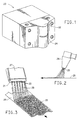
- a spinneret pack 20 for flash-spinning a plexifilamentary web is illustrated.
- the pack 20 is preferably made of a high strength alloy such as T316 Stainless Steel.
- Pack 20 includes an elongated outwardly contoured portion 22 with a semicircular slot opening 24 therein.
- Spin pack 20 is mountable on the end of a flash spinning apparatus 26, as shown in Figure 2, that is similar to the spinning apparatus disclosed in U.S. Patent 3,484,899 to Smith.
- Spinning apparatus 26 is preferably mounted above a moving belt 28 such that plexifilamentary material spun from spin pack 20 can be collected on moving belt 28.
- an alternative spin pack 21, with multiple spinning slots 23, is shown mounted on a spinning apparatus 27 above a belt 28.
- FIG. 4-6 Cross-sectional views of the slot 24 are shown in Figures 4-6.
- the following description of the slot 24 also describes the individual slots 23 of the spin pack 21 shown in Figure 3.
- a slot is positioned immediately downstream of a substantially cylindrical spinning orifice 36 like the orifice of U.S.
- slot 24 is defined by opposite faces 38 and 40. Faces 38 and 40 diverge from each other such that the width of slot 24 increases with distance from spin orifice 36, as is shown in Figure 4. Faces 38 and 40 may be flat or convex. The space between faces 38 and 40 of slot 24 should be narrow enough to distort the pressure field of a pressurized mixture of polymer and spin agent discharging from spin orifice 36 and expanding within the slot 24.
- the mixture expands into a larger area and the pressure of the mixture decreases.
- the spin agent begins to expand, but the expansion is constrained by the slot faces 38 and 40 such that a film of the mixture of polymer and spin agent is pushed radially outward in a fan-like pattern.
- the mixture begins its fan-like expansion in a liquid state within the zone 44, as can be seen in Figures 5 and 6.
- the pressure decreases until an interface 43 is reached at which point the spin agent begins to vaporize and polymer fibrils begin to form.
- the mixture's pressure continues to decrease which generates greater expansion and flash vaporization of the spin agent.
- the slot 24 diverges too quickly, the polymer and spin agent mixture exiting the orifice will maintain the cylindrical shape of orifice 36 as it passes through the slot 24. If, on the other hand, faces 38 and 40 are too close, plugging of slot 24 is likely, especially at higher throughputs.
- the slot faces diverge from each other at an angle of approximately 0.5° to 5° in order to prevent sticking or spitting of polymer.
- the faces 38 and 40 may also be highly polished or they may be coated with a non-stick coating such as a TEFLON® non-stick finish to reduce sticking and spitting of the polymer.
- TEFLON® is a registered trademark of DuPont.
- the distance between faces 38 and 40 proximate the opening of spinning orifice 36 is about 0.9 mm while the distance between the faces 38 and 40 at the opening edge 48 of slot 24 is about 1.4 mm.
- the distance from the opening of orifice 36 to the outer opening edge 48 of slot 24 is between about 5 and 15 mm. It is also preferred that the area of the opening of slot 24 be between 100 and 130 times the cross-sectional area of the opening of orifice 36.
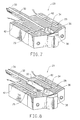
- FIG 7 is a perspective cross-sectional view of spin pack 20 into which a spin orifice and slot, like that described above with reference to Figures 4-6, are incorporated.
- Pack 20 includes a high pressure connector 30 that mounts on spinning apparatus 26.
- connector 30 comprises a metal-to-metal tapered conical seat held in place by a threaded coupling.
- a passage 32 in connector 30 supplies polymer and spin agent to a chamber 34.
- Passage 32 preferably has a diameter between about 6 and 9 mm, and a length of between about 100 and 150 mm.
- chamber 34 has a diameter at least several times that of the diameter of passage 32.
- chamber 34 may be cylindrically shaped with a tapered end opposite the chamber inlet and the chamber may have a diameter between 15 and 20 mm.
- the volume of chamber 34 is preferably about 3500 mm 3 .
- Chamber 34 of spin pack 20 may act as a letdown chamber in systems where a polymer is flash-spun from a solution as described in U.S. Patent 3,227,794 to Anderson et al. In such solution flash-spinning systems, the polymer enters chamber 34 in solution, but the reduced pressure within the chamber 34 promotes nucleation of a very fine dispersion of solvent in the polymer solution that facilitates formation of plexifilamentary strands upon being spun through an orifice. Chamber 34 provides a constant flow of the mixture of polymer and spin agent into the spin orifice during flash-spinning. When a mixture of polymer and spin agent enters the chamber 34, the pressure of the mixture drops.
- the pressure of the mixture within the chamber 34 depends on the polymer, the spin agent, and the spinning process used. In some systems the pressure within chamber 34 may be as low as 5000 kPa, while in other systems the pressure may be as high as 35,000 kPa.
- a second upstream chamber 33 may be added to the spin pack to serve as a site for a polymer filter or a static mixing device.
- One static mixing device that has been beneficially used in conjunction with the invention is a static mixer comprised of Model SMX mixing elements that have been welded together, as sold by Koch Engineering Company, Inc. of Wichita, Kansas.
- the faces 38 and 40 of the slot may be maintained at an elevated temperature by a plurality of heating elements 42 that are inserted in the bore holes 29 of the pack 20.
- the heating elements 42 may be 3/8 inch diameter 400 joule/sec electrical resistance heating elements manufactured by Watlow, Inc. of Saint Louis, Missouri.
- the spin pack may be heated with steam that circulates through steam passages in the spin pack.
- the heating elements 42 counter the cooling that arises from the adiabatic expansion of spin agent in slot 24.
- heating elements prevent polymer sticking by keeping the temperature of the pack at a temperature higher than the melting point of the polymer being spun.
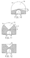
- slot 24 is formed between projecting shields rather than being formed in an outwardly extending contour of the spin pack 20 (as shown in Figure 1).
- the spin slot shown in Figure 10 would be expected to perform satisfactorily in the spinning of polymers with low melting points where cooling of the faces 38 and 40 ( Figure 4) is less likely to result in polymer sticking.
- Figure 10 shows a downward cross-sectional view of this alternative embodiment.
- the slot 24 is formed between faces 38 and 40, and the slot is angled back from the spin orifice 36 at an angle ⁇ , so as to facilitate greater spreading of a web spun from the spin orifice.
- a slot tapered at an angle ⁇ can be used.
- the angled geometries of the slot 24, as shown in Figures 10 and 11, could be incorporated into the spin pack embodiment shown in Figure 1.
- the diverging opposing faces that define the slot 24 shown in Figure 4 are incorporated into the embodiments of the invention shown in Figures 10 and 11.
- the spinning slots of Figures 4, 10 and 11 can also be used in spin packs having multiple spinning slots. As shown in Figure 3, multiple spinning slots 23, each similar to slot 24 of Figure 4, can be combined in an elongated spin pack 21. Slots 23 are preferably arranged in an offset and parallel fashion as shown in Figure 3. The thin nature of the plexifilamentary web spun from each slot makes it possible to position adjacent slots close enough to each other that the web spun from each slot overlaps the web spun from the adjacent slot so as to form a continuous curtain 29.
- the plexifilamentary curtain can be laid down on a moving belt 28 to form a continuous sheet 25 of plexifilamentary material.
- each of the slots 23 in spin pack 21 receives polymer and spin agent through a spin orifice similar to the orifice 36 of Figure 4.
- each spin orifice in the elongated spin pack 21 preferably receives polymer and spin agent from a chamber 34. In some instances, it may be desirable to have a single chamber connected to multiple spin orifices.
- resistance heating elements or steam heating conduits may be incorporated into the elongated spin pack 21 to help prevent polymer from sticking to the faces of the slots.
- more readily heatable fully internal slots may be incorporated into the elongated spin pack 21.
- Such internal slots should be especially effective in spin packs having a large number of very small spinning slots. While the internal edges of the slot 38 are shown as straight edges in Figures 10, 11 and 12, the internal edges of slot 38 may be curved or otherwise contoured to obtain a desired web distribution.
- the denier of the web is determined from the weight of a 15 cm sample length of web.
- Tenacity, elongation and toughness of the flash-spun web are determined with an Instron tensile-testing machine. The webs are conditioned and tested at 21°C (70°F) and 65% relative humidity. The webs are then twisted to 3.94 turns per cm (10 turns per inch) and mounted in the jaws of the Instron tester. A 5.08 cm (2 inch) length was used with an initial elongation rate was 10.16 cm/min (4 inches per minute). The tenacity at break is recorded in grams per deciTex (gpdT) (grams per denier (gpd)). The elongation at break is recorded as a percentage of the original gauge length of the sample. Toughness is a measure of the work required to break the sample divided by the denier of the sample and is recorded in gpd.
- Fiber quality is evaluated using a subjective scale of 0 to 3, with a 3 being the highest quality rating.
- a 25.4 cm (10 inch) length of a plexifilamentary web is removed from a fiber batt. The web is spread and mounted on a dark substrate.
- the fiber quality rating is an average of three subjective ratings, one for fineness of the fiber (finer fibers receive higher ratings), one for the continuity of the fiber web (continuous plexifilamentary webs receive a higher rating), and the other for the frequency of the ties (more networked plexifilamentary webs receive a higher rating).
- the basis weights reported for the examples below are each based on an average of at least twelve measurements made on the sample.
- Mass Deposition Uniformity was determined by measuring the average mass of the sheet with a beta gauge over an area of approximately 1 cm 2 .
- the mass deposition uniformity value ( ⁇ ) represents the statistical standard deviation of the measured mass values. A lower standard deviation is indicative of a more uniform sheet.
- the coefficient of variation is equal to 100( ⁇ /avg. basis weight).
- a plexifilamentary web comprised of ALATHON® H6018 and SELAR® OH BX240 was spun from a spin pack like that shown in Figures 1 and 7.
- ALATHON® H6018 is a high density polyethylene that was obtained from Occidental Chemical Corporation of Houston. Texas.
- ALATHON® is a registered trademark of Lyondell Petrochemical Company of Houston, Texas.
- the ALATHON® H6018 had a melt flow rate of 17.5 g/10 min by standard techniques at a temperature of 190°C with a 2.16 kg weight, and had a melting point of 130°-135° C.
- the SELAR® OH BX240 was obtained from DuPont.
- SELAR® is a registered trademark of DuPont.
- SELAR® OH BX240 is a melt-blended, pelletized polymer consisting of 90% SELAR® OH 4416 and 10% FUSABOND® E MB-259D, both polymers being obtained from DuPont.
- FUSABOND® is a registered trademark of DuPont Canada.
- SELAR® OH 4416 is an ethylene vinyl alcohol copolymer having 44 mole % ethylene units, a melt flow rate of 16.0 g/10 min by standard techniques at a temperature of 210° C with a 2.16 kg weight, and a melting point of 168° C.
- FUSABOND® E MB-259D is a polyethylene grafted with 0.2-0.3% maleic anhydride, with a melt flow rate of 20-25 g/10 min by standard techniques at a temperature of 190° C with a 2.16 kg weight, and with a melting point of 120-122° C.
- a polymer blend of 90% ALATHON® H6018 and 10% SELAR® OH BX240 was continuously heat extruded and injected under pressure into a high shear continuous rotary mixer. Inside the mixer, the polymer blend was plasticized with supercritical CO 2 and was mixed with water. The mixing ratio of CO 2 to polymer (by weight) was maintained at approximately 1.2. The mixing ratio of water to polymer (by weight) was maintained at approximately 0.9. The polymer, CO 2 and water mixture was maintained within the mixer at a pressure of approximately 30,000 kPa and at a temperature of approximately 220°C.
- the mixture was transferred through a heated and insulated transfer line to a spin pack like that shown in Figures 1 and 7.
- a 200 micrometer (micron) filter was placed in the transfer line between the mixer outlet and the spin pack.
- the mixture was fed into a 3,930 mm 3 chamber in the spin pack and then through the pack's spin orifice.
- the spin orifice had a diameter of 0.79 mm and a length to diameter ratio of 0.23.
- the distance between the opposite faces of the spin pack slot proximate the spin pack orifice was 0.91 mm. At the exit opening of the slot, the distance between the faces was 1.14 mm.
- the distance from the spin orifice to the exit opening of the spin pack slot was 9.55 mm.
- the pressure of the mixture in the spin pack chamber was about 28,000 kPa.
- a collapsed tubular web of finely fibrillated, soft plexifilamentary strands was continuously spun from the slot during a production period lasting approximately 15 minutes.
- the web was laid down directly on a moving belt without passing through an electric corona.
- the web was 30 to 40 cm wide with occasional holes and breaks.
- the web had a tex of approximately 100 and the web's tenacity was approximately 0.6 gpd.
- a plexifilamentary web comprised of a blend of 50% CRASTIN® 6131 polyester, 35% CRASTIN® 6130 polyester, 5% HYTREL® 6133 polyether ester, and 10% Valtec HH444 polypropylene was spun from a spin pack like that shown in Figures 1 and 8.
- CRASTIN® 6131 is a non-reinforced low molecular weight 4GT polyester obtained from DuPont.
- CRASTIN® is a registered trademark of DuPont.
- CRASTIN® 6131 was formerly sold under the name RYNITE® 6131.
- CRASTIN® 6131 has a melt flow rate of 42 g/10 min by standard techniques at a temperature of 250° C with a 2.16 kg weight, and has a melting point of 225° C.
- CRASTIN® 6130 is a non-reinforced 4GT polyester obtained from DuPont that has a higher molecular weight than CRASTIN® 6131.
- CRASTIN® 6130 has a melt flow rate of 12.5 g/10 min by standard techniques at a temperature of 250° C with a 2.16 kg weight, and has a melting point of 225° C.
- HYTREL® 6133 is a melt spinnable polyether ester block copolymer obtained from DuPont. HYTREL® is a registered trademark of DuPont.
- HYTREL® has a melt flow rate of 5.0 g/10 min by standard techniques at a temperature of 190° C with a 2.16 kg weight, and it has a melting point in the range of 170°-190° C.
- Valtec HH444 is a melt spinnable polypropylene obtained from Himont Corporation of Wilmington, Delaware. Valtec HH444 has a melt flow rate of 70g/10 min by standard techniques at a temperature of 190° C with a 2.16 kg weight, and has a melting point of 170° C.
- the polymer blend of 50% CRASTIN® 6131 polyester, 35% CRASTIN® 6130 polyester, 5% HYTREL® 6133 polyether ester, and 10% Valtec HH444 polypropylene was continuously heat extruded and injected under pressure into a high shear continuous rotary mixer during a production period that lasted approximately 15 minutes. Inside the mixer, the polymer blend was plasticized with supercritical CO 2 and was mixed with water. The mixing ratio of polymer to CO 2 (by weight) was maintained at approximately 1.25. The mixing ratio of polymer to water (by weight) was maintained at approximately 2.86. The polymer, CO 2 and water mixture was maintained within the mixer at a pressure of approximately 29,000 kPa and at a temperature of approximately 235°C.
- the mixture was transferred through a heated and insulated transfer line to a spin pack like that shown in Figures 1 and 8.
- a 440 micrometer (micron) filter was placed in the transfer line between the mixer outlet and the spin pack.
- the mixture was fed into a 3,930 mm 3 chamber in the spin pack where it passed through a four element in-line static mixer placed approximately 3.2 cm (1.25 in) upstream of the spin orifice.
- the static mixer had a cylindrical sleeve that held four Model SMX static mixing elements that had been welded together to form a mixing insert, as sold by Koch Engineering Company, Inc. of Wichita, Kansas.
- the spin orifice had a diameter of 0.79 mm and a length to diameter ratio of 0.31.
- the distance between the opposite faces of the spin pack slot proximate the spin pack orifice was 1.35 mm. At the exit opening of the slot the distance between the faces was 1.75 mm. The distance from the spin orifice to the exit opening of the spin pack slot was 12.75 mm. The pressure of the mixture in the spin pack chamber was about 29,000 kPa.
- a finely fibrillated plexifilamentary web was continuously spun from the slot during the 15 minute production period.
- the web was laid down directly on a moving belt without passing through an electric corona.
- the web was about 40 cm wide, it had a tenacity of 2.9 gpdT (2.6 gpd), an elongation of 37%, a toughness of 0.7 gpdT (0.6 gpd), and a fiber quality rating of 2.5.
- ALATHON® 7026 was obtained from Occidental Chemical Corporation of Houston, Texas.
- ALATHON® is a registered trademark of Lyondell Petrochemical Company of Houston, Texas.
- ALATHON® 7026 has a density of 0.95 g/cm 3 , a melt flow rate of 0.85 g/10 min as determined by ASTM method D-1238-57T, condition E, and a melting point in the range of 127° to 141° C.
- a solution of the ALATHON® 7026 polyethylene was flash-spun from a hot trichlorofluoromethane spin agent.
- Trichlorofluoromethane boils at about 24° C, has a critical temperature of 198° C, and a critical pressure of 4410 kPa (640 psi).
- the polyethylene and spin agent solution was mixed in a five gallon autoclave equipped with a motor-driven helical blade agitator, a temperature control, a pressure measuring control, a steam-heated jacket, inlets for loading ingredients, and a discharge line.
- the discharge line was connected, through a quick acting valve and a jacketed transfer line, to a flash-spinning assembly with 14 spinning nozzles.
- the autoclave was opened and 2350 grams of ALATHON® 7026 were added to the clave's mixing chamber at a temperature below about 120° C.
- the autoclave was closed and evacuated to remove oxygen.
- 17,230 grams of trichlorofluoromethane spin agent was added, in liquid state, to the clave's mixing chamber through an inlet line.
- the mixture in the clave comprised 12% polyethylene polymer and 88% spin agent.
- the agitator mixed the polymer and spin agent as the clave was gradually heated to a temperature of 180° C over a period of about 1 hour.
- the pressure in the clave was about 10,340 kPa ( about 1500 psi), the polymer was fully dissolved in the spin agent, and the solution displaced the entire capacity of the clave.
- the agitator was stopped and the polymer solution was discharged to the fourteen nozzle spinning assembly.
- Discharge of the polymer solution was accomplished by opening the discharge line valve and driving the solution out of the clave by introducing Nitrogen into the mixing chamber at a pressure of about 12,065 kPa (about 1750 psi).
- the polymer solution was directed through the heated transfer line to a distribution channel from which the polymer entered a "coat hanger"-shaped distribution chamber from which the polymer entered the fourteen spin orifices.
- Each of the fourteen spin orifices had a tapered inlet through which polymer passed from the distribution chamber to a 0.508 mm (20 mil) orifice through which the solution entered one of fourteen corresponding cylindrically shaped letdown chambers.
- Each letdown chamber had opposite conically-tapered ends. The end of each letdown chamber proximate the chamber's inlet orifice was conically-tapered at an angle of 60° and the opposite end of each letdown chamber (proximate the spinning orifice) was conically-tapered at an angle of 80°.
- the straight section of the letdown chamber between the conically-tapered ends had a length of 6.35 cm and a diameter of 10.2 mm.
- the pressure within the letdown chambers during spinning was about 6757 kPa (980 psi).
- the polymer and spin agent were discharged from each letdown chamber through each chamber's spinning orifice.
- the fourteen spinning orifices were arranged in a straight line and were spaced on 19.05 mm (0.75 in) centers. Each spinning orifice had a diameter of 0.508 mm and a length to diameter ratio of 1. Each spin orifice discharged into a slot like that shown in Figure 12. The slot had opposite parallel faces spaced 1.106 mm from each other proximate the orifice and proximate the exit opening of the slot. The distance from each spin orifice to the exit opening of the spin pack slot was 9.53 mm along the centerline of polymer flow. The central plane of each slot formed an angle of 25° with the plane passing through the centerline of the fourteen spin orifices.
- a finely fibrillated plexifilamentary web was continuously spun from the slots during a production period of approximately 1.5 minutes.
- the web was laid down directly on a moving belt spaced 20.3 cm (8 in) below the slot openings without passing through an electric corona.
- the web was initially pinned to the belt with suction and was subsequently stabilized by passing the web through a corona swath charger.
- the web had a total width of about 33 cm (13 in) with a central 23 cm (9 in) wide portion that had an average basis weight of 54.3 g/m 2 .
- the machine direction uniformity of mass deposition was characterized by a coefficient of variation of 0.15 as measured using 1.0 cm 2 sample sizes.
Landscapes
- Engineering & Computer Science (AREA)
- Mechanical Engineering (AREA)
- Textile Engineering (AREA)
- Spinning Methods And Devices For Manufacturing Artificial Fibers (AREA)
Claims (9)
- Spinnbaugruppe (20,21) für eine Flash-Spinnvorrichtung, die aufweist:einen Spinnbaugruppenkörper;einen Spinnmischungseintritt (30) im Spinnbaugruppenkörper;einen Spinnmischungsdurchgang (32) im Spinnbaugruppenkörper, wobei der Spinnmischungsdurchgang ein erstes und zweites Ende aufweist, wobei das erste Ende des Spinnmischungsdurchganges mit dem Spinnmischungseintritt (30) in Verbindung ist;eine Spinndüse (36) mit einer Querschnittsfläche im Bereich von 0,0025 mm2 bis 32 mm2, wobei die Spinndüse einen Eintritt und einen Austritt aufweist, wobei der Eintritt der Spinndüse mit dem zweiten Ende des Spinnmischungsdurchganges (32) in Verbindung steht; undeinen Schlitz (23, 24) mit einem Schlitzaustritt, der durch zwei divergierende gegenüberliegende Flächen (38, 40) des Spinnbaugruppenkörpers stromabwärts vom Spinndüsenaustritt definiert wird, wobei sich der Austritt der Spinndüsen in den Schlitz hinein öffnet, wobei der Abstand zwischen den gegenüberliegenden Flächen, die den Schlitz (23, 24) definieren, innerhalb des Bereiches von 0,25 mm bis 7 mm in unmittelbarer Nähe des Spinndüsenaustrittes liegt, wobei der Abstand vom Spinndüsenaustritt zu irgendeinem Abschnitt des Schlitzaustrittes innerhalb des Bereiches von 1,5 mm bis 40 mm liegt, und wobei der Abstand zwischen den gegenüberliegenden Flächen (38, 40) im Schlitzaustritt innerhalb des Bereiches von 0,25 mm bis 10 mm liegt.
- Flash-Spinnbaugruppe (20, 21) nach Anspruch 1, die außerdem Heizelemente (42) im Spinnbaugruppenkörper für die Aufrechterhaltung der Temperatur des Spinnbaugruppenkörpers auf einer gewünschten Spinntemperatur aufweist.
- Flash-Spinnbaugruppe nach Anspruch 1, bei der der Schlitzaustritt eine im wesentlichen halbkreisförmige Form aufweist, die um den Spinndüsenaustritt herum zentriert ist.
- Flash-Spinnbaugruppe nach Anspruch 3, bei der die Spinndüse (36) einen im wesentlichen runden Querschnitt mit einem Durchmesser im Bereich von 0,5 mm bis 1,2 mm aufweist.
- Flash-Spinnbaugruppe nach Anspruch 4, bei der die gegenüberliegenden Flächen des Schlitzes (38, 40) voneinander unter einem Winkel zwischen 0,5° und 5° zwischen dem Austritt der Spinndüse und dem Schlitzaustritt divergieren.
- Flash-Spinnbaugruppe (20, 21) nach Anspruch 1, bei der die Spinnbaugruppe umfaßt:eine Vielzahl von Spinndüse (36) mit einer Querschnittsfläche im Bereich von 0,0025 mm2 bis 3,0 mm2, wobei jede Spinndüse (36) einen Eintritt und einen Austritt aufweist, wobei der Eintritt der Spinndüsen mit dem Spinnmischungsdurchgang (32) in Verbindung steht; undeine Vielzahl von Schlitzen (23, 24), wobei jeder durch zwei divergierende gegenüberliegende Flächen (38, 40) des Spinnbaugruppenkörpers stromabwärts vom entsprechenden Spinndüsenaustritt definiert wird, wobei sich der Austritt einer jeden der Vielzahl von Spinndüsen (36) in einen anderen der Vielzahl von Schlitzen (23, 24) hinein öffnet, wobei der Abstand zwischen den gegenüberliegenden Flächen (38, 40), die jeden Schlitz definieren, innerhalb des Bereiches von 0,15 mm bis 7 mm in unmittelbarer Nähe des Spinndüsenaustrittes liegt, wobei der Abstand von jedem Spinndüsenaustritt zu irgendeinem Abschnitt des entsprechenden Schlitzaustrittes innerhalb des Bereiches von 1,5 mm bis 40 mm liegt, und wobei der Abstand zwischen den gegenüberliegenden Flächen (38, 40) im Schlitzaustritt innerhalb des Bereiches von 0,25 mm bis 10 mm liegt.
- Flash-Spinnbaugruppe nach Anspruch 6, bei der die Spinndüsen (36) in die gleiche Richtung zeigen und von benachbarten Düsen (36) mit im wesentlichen gleichen Abständen längs einer geraden Linie beabstandet sind, worin jeder der Vielzahl von Schlitzen (23, 24) eine mittlere Ebene definiert, die gleichweit zwischen den gegenüberliegenden Flächen (38, 40) des Schlitzes (23, 24) beabstandet ist, worin die mittlere Ebene eines jeden der Schlitze (23, 24) im wesentlichen parallel zu den mittleren Ebenen der anderen Schlitze (23, 24) verläuft, und worin die Mittellinie einer jeden Spinndüse (36) in der mittleren Ebene des entsprechenden Schlitzes (23, 24) liegt.
- Flash-Spinnbaugruppe (20, 21) nach Anspruch 7, bei der ein Winkel zwischen der mittleren Ebene eines jeden Schlitzes (23, 24) und einer Ebene gebildet wird, die durch die Mittellinie einer jeden Spinndüse (36) hindurchgeht, und wobei der Winkel innerhalb des Bereiches von 5° bis 45° liegt.
- Flash-Spinnbaugruppe (20, 21) nach Anspruch 8, bei der die Vielzahl der Spinndüsen (36) mindestens fünf Spinndüsen (36) aufweist.
Applications Claiming Priority (5)
| Application Number | Priority Date | Filing Date | Title |
|---|---|---|---|
| US2197296P | 1996-06-27 | 1996-06-27 | |
| US21972P | 1996-06-27 | ||
| US870995 | 1997-06-06 | ||
| US08/870,995 US5788993A (en) | 1996-06-27 | 1997-06-06 | Spinneret with slotted outlet |
| PCT/US1997/011079 WO1997049846A1 (en) | 1996-06-27 | 1997-06-25 | Spinneret for flash-spinning |
Publications (2)
| Publication Number | Publication Date |
|---|---|
| EP0907770A1 EP0907770A1 (de) | 1999-04-14 |
| EP0907770B1 true EP0907770B1 (de) | 2002-11-06 |
Family
ID=26695324
Family Applications (1)
| Application Number | Title | Priority Date | Filing Date |
|---|---|---|---|
| EP97931417A Expired - Lifetime EP0907770B1 (de) | 1996-06-27 | 1997-06-25 | Spinndüse zum flash-spinnen |
Country Status (6)
| Country | Link |
|---|---|
| US (1) | US5788993A (de) |
| EP (1) | EP0907770B1 (de) |
| KR (1) | KR20000022259A (de) |
| CA (1) | CA2257037A1 (de) |
| DE (1) | DE69716908T2 (de) |
| WO (1) | WO1997049846A1 (de) |
Families Citing this family (27)
| Publication number | Priority date | Publication date | Assignee | Title |
|---|---|---|---|---|
| AU1802499A (en) * | 1997-12-03 | 1999-06-16 | Ason Engineering, Inc. | Nonwoven fabrics formed from ribbon-shaped fibers and method and apparatus for making the same |
| US6336801B1 (en) | 1999-06-21 | 2002-01-08 | Kimberly-Clark Worldwide, Inc. | Die assembly for a meltblowing apparatus |
| US7135251B2 (en) * | 2001-06-14 | 2006-11-14 | Samsung Sdi Co., Ltd. | Active material for battery and method of preparing the same |
| JP4621658B2 (ja) * | 2003-04-03 | 2011-01-26 | イー・アイ・デュポン・ドウ・ヌムール・アンド・カンパニー | 均質な材料を形成させるためのローター式方法 |
| JP4594929B2 (ja) * | 2003-04-03 | 2010-12-08 | イー・アイ・デュポン・ドウ・ヌムール・アンド・カンパニー | 一様に分配された材料の形成方法 |
| CN101580968B (zh) * | 2004-04-01 | 2011-07-27 | 纳幕尔杜邦公司 | 形成均匀材料的旋转法 |
| US20070202764A1 (en) * | 2005-04-01 | 2007-08-30 | Marin Robert A | Rotary process for forming uniform material |
| US20080006970A1 (en) * | 2006-07-10 | 2008-01-10 | General Electric Company | Filtered polyetherimide polymer for use as a high heat fiber material |
| US9416465B2 (en) * | 2006-07-14 | 2016-08-16 | Sabic Global Technologies B.V. | Process for making a high heat polymer fiber |
| MX360481B (es) | 2010-07-02 | 2018-11-05 | Procter & Gamble | Articulo con estructura soluble de trama fibrosa que comprende agentes activos. |
| WO2015164227A2 (en) | 2014-04-22 | 2015-10-29 | The Procter & Gamble Company | Compositions in the form of dissolvable solid structures |
| CN115341342B (zh) * | 2022-08-24 | 2024-05-07 | 厦门当盛新材料有限公司 | 多喷孔喷头、闪纺设备和闪纺方法 |
| KR20260030724A (ko) | 2023-06-30 | 2026-03-06 | 듀폰 세이프티 앤드 컨스트럭션, 인크. | 표면 견고성이 개선된 통기성 시트 |
| WO2025006920A1 (en) | 2023-06-30 | 2025-01-02 | Dupont Safety & Construction, Inc. | Softened flash-spun sheet |
| WO2025006914A1 (en) | 2023-06-30 | 2025-01-02 | Dupont Safety & Construction, Inc. | Breathable tear resistant flash-spun sheet |
| KR20260030725A (ko) | 2023-06-30 | 2026-03-06 | 듀폰 세이프티 앤드 컨스트럭션, 인크. | 고차단성 통기성 플래시 방사 시트 |
| EP4689264A1 (de) | 2023-06-30 | 2026-02-11 | DuPont Safety & Construction, Inc. | Weiche, flash-gesponnene folie |
| KR20260030728A (ko) | 2023-06-30 | 2026-03-06 | 듀폰 세이프티 앤드 컨스트럭션, 인크. | 방풍 플래시 방사 시트 |
| WO2025144674A1 (en) | 2023-12-27 | 2025-07-03 | Dupont Safety & Construction, Inc. | Azeotropic and azeotrope-like compositions comprising dichloromethane and trans-1h,2h-octafluorocyclopentane and use of the compositions as flash spinning agents |
| WO2025144673A1 (en) | 2023-12-27 | 2025-07-03 | Dupont Safety & Construction, Inc. | Non-azeotropic compositions comprising dichloromethane and 1h,1h,2h-heptafluorocyclopentane and use of the compositions as flash spinning agents |
| WO2025144676A1 (en) | 2023-12-27 | 2025-07-03 | Dupont Safety & Construction, Inc. | Flash spinning process and flash spinning fluid |
| WO2025178741A1 (en) | 2024-02-19 | 2025-08-28 | Dupont Safety & Construction, Inc. | Azeotropic and azeotrope-like compositions comprising 1,2-dichloroethylene and 1h,2h-octafluorocyclopentane and use of the compositions as flash spinning agents |
| WO2025178740A1 (en) | 2024-02-19 | 2025-08-28 | Dupont Safety & Construction, Inc. | Azeotropic and azeotrope-like compositions comprising cyclopentane and 1h,1h,2h-heptafluorocyclopentane or 2-methylpentane and 1h,1h,2h-heptafluorocyclopentane and use of the compositions as flash spinning agents |
| WO2025240708A1 (en) | 2024-05-17 | 2025-11-20 | Dupont Safety & Construction, Inc. | Improved flash spinning process for polyolefins using flash spinning agents comprising a chlorinated solvent and a linear or branched hydrocarbon with 5 to 6 carbon atoms |
| WO2025240715A1 (en) | 2024-05-17 | 2025-11-20 | Dupont Safety & Construction, Inc. | Azeotropic and azeotrope-like compositions comprising dichloromethane and 2-methylpentane or 3-methylpentane and use of the compositions as flash spinning agents |
| WO2025240719A1 (en) | 2024-05-17 | 2025-11-20 | Dupont Safety & Construction, Inc. | Flash spinning process for partially fluorinated polymers using flash spinning agents comprising a chlorinated solvent and a linear or branched hydrocarbon with 5 or more carbon atoms |
| WO2025240722A1 (en) | 2024-05-17 | 2025-11-20 | Dupont Safety & Construction, Inc. | Azeotropic and azeotrope-like compositions comprising a chlorinated compound and a c6-hydrocarbon and use of the compositions as flash spinning agents |
Family Cites Families (15)
| Publication number | Priority date | Publication date | Assignee | Title |
|---|---|---|---|---|
| US2367451A (en) * | 1943-03-30 | 1945-01-16 | Harry H West | Heater for extrusion nozzles |
| US3081519A (en) * | 1962-01-31 | 1963-03-19 | Fibrillated strand | |
| US3315020A (en) * | 1962-03-21 | 1967-04-18 | Gore & Ass | Process for preparing biaxially fibrillated sheets |
| NL300881A (de) * | 1962-11-23 | |||
| US3387326A (en) * | 1964-06-04 | 1968-06-11 | Du Pont | Apparatus for charging and spreading a web |
| US3484899A (en) * | 1967-04-06 | 1969-12-23 | Du Pont | Spinneret pack for flash extrusion |
| BE787033A (de) * | 1971-08-06 | 1973-02-01 | Solvay | |
| US4025593A (en) * | 1971-08-06 | 1977-05-24 | Solvay & Cie | Fabrication of discontinuous fibrils |
| US3756441A (en) * | 1972-08-14 | 1973-09-04 | Du Pont | Flash spinning process |
| US4179875A (en) * | 1975-11-20 | 1979-12-25 | Fiber Industries, Inc. | High tenacity, low denier poly(ethylene terephthalate) fibrillated tape yarn |
| US4352650A (en) * | 1981-03-24 | 1982-10-05 | E. I. Du Pont De Nemours And Company | Nozzle for flash-extrusion apparatus |
| DE3308626C2 (de) * | 1983-03-11 | 1986-02-20 | Dynamit Nobel Ag, 5210 Troisdorf | Verfahren zur Herstellung von Fibriden aus thermoplastischen Kunststoffen |
| CA2029550C (en) * | 1989-11-22 | 2001-07-31 | Don Mayo Coates | Process for flash spinning polyolefins |
| US5279776A (en) * | 1991-09-17 | 1994-01-18 | E. I. Du Pont De Nemours And Company | Method for making strong discrete fibers |
| GB9223563D0 (en) * | 1992-11-10 | 1992-12-23 | Du Pont Canada | Flash spinning process for forming strong discontinuous fibres |
-
1997
- 1997-06-06 US US08/870,995 patent/US5788993A/en not_active Expired - Lifetime
- 1997-06-25 KR KR1019980710679A patent/KR20000022259A/ko not_active Withdrawn
- 1997-06-25 DE DE69716908T patent/DE69716908T2/de not_active Expired - Lifetime
- 1997-06-25 WO PCT/US1997/011079 patent/WO1997049846A1/en not_active Ceased
- 1997-06-25 EP EP97931417A patent/EP0907770B1/de not_active Expired - Lifetime
- 1997-06-25 CA CA002257037A patent/CA2257037A1/en not_active Abandoned
Also Published As
| Publication number | Publication date |
|---|---|
| DE69716908D1 (de) | 2002-12-12 |
| DE69716908T2 (de) | 2003-08-21 |
| EP0907770A1 (de) | 1999-04-14 |
| KR20000022259A (ko) | 2000-04-25 |
| CA2257037A1 (en) | 1997-12-31 |
| WO1997049846A1 (en) | 1997-12-31 |
| US5788993A (en) | 1998-08-04 |
Similar Documents
| Publication | Publication Date | Title |
|---|---|---|
| US5788993A (en) | Spinneret with slotted outlet | |
| CA2137649C (en) | High speed spinning of multi-component fibers with high hole surface density spinnerettes and high velocity quench | |
| EP0877835B1 (de) | Fasern aus polyolefinmischungen nach dem flash-spinnverfahren | |
| EP0381206B2 (de) | Verfahren zur Herstelung von Fasern, Rovings und Matten aus flüssigkristallinen lyotropen Polymeren | |
| EP1656474B1 (de) | Drehverfahren zur herstellung eines einheitlichen materials | |
| JP4851681B2 (ja) | メルトブローンウエブ | |
| EP2129816B1 (de) | Herstellung von nanofasern durch schmelzspinnen | |
| JPS61179246A (ja) | ポリエチレンとポリプロピレンとのブレンド | |
| EP0957187A2 (de) | Vorrichtung und Verfahren zur Herstellung von Mikrofilamenten von hoher Titer-Gleichmässigkeit aus thermoplastischen Polymeren | |
| US10590565B2 (en) | Polymeric nanofibers and nanofibrous web | |
| MXPA02011207A (es) | Conjunto de placa rompedora para producir fibras de bicomponente en un aparato de soplado con fusion. | |
| US20050054254A1 (en) | Method for making a nonwoven web | |
| CA2408304C (en) | Process and device for the transport of continuous moldings without tensile stress | |
| JPH05195307A (ja) | マルチフィル糸の溶融紡糸装置及びフィラメント糸の製法 | |
| EP0900288B1 (de) | Flah-spinnvorrichtung und verfahren | |
| EP1563127B1 (de) | Spinnplatte mit unrunden Löchern | |
| EP0842311A2 (de) | Verfahren zum verändern der porosität bei der herstellung einer schicht aus flash-gesponnenem olefinpolymer |
Legal Events
| Date | Code | Title | Description |
|---|---|---|---|
| PUAI | Public reference made under article 153(3) epc to a published international application that has entered the european phase |
Free format text: ORIGINAL CODE: 0009012 |
|
| 17P | Request for examination filed |
Effective date: 19981210 |
|
| AK | Designated contracting states |
Kind code of ref document: A1 Designated state(s): DE ES FR GB IT |
|
| 17Q | First examination report despatched |
Effective date: 20001102 |
|
| GRAG | Despatch of communication of intention to grant |
Free format text: ORIGINAL CODE: EPIDOS AGRA |
|
| GRAG | Despatch of communication of intention to grant |
Free format text: ORIGINAL CODE: EPIDOS AGRA |
|
| GRAH | Despatch of communication of intention to grant a patent |
Free format text: ORIGINAL CODE: EPIDOS IGRA |
|
| GRAH | Despatch of communication of intention to grant a patent |
Free format text: ORIGINAL CODE: EPIDOS IGRA |
|
| GRAA | (expected) grant |
Free format text: ORIGINAL CODE: 0009210 |
|
| AK | Designated contracting states |
Kind code of ref document: B1 Designated state(s): DE ES FR GB IT |
|
| PG25 | Lapsed in a contracting state [announced via postgrant information from national office to epo] |
Ref country code: IT Free format text: LAPSE BECAUSE OF FAILURE TO SUBMIT A TRANSLATION OF THE DESCRIPTION OR TO PAY THE FEE WITHIN THE PRESCRIBED TIME-LIMIT;WARNING: LAPSES OF ITALIAN PATENTS WITH EFFECTIVE DATE BEFORE 2007 MAY HAVE OCCURRED AT ANY TIME BEFORE 2007. THE CORRECT EFFECTIVE DATE MAY BE DIFFERENT FROM THE ONE RECORDED. Effective date: 20021106 |
|
| REG | Reference to a national code |
Ref country code: GB Ref legal event code: FG4D |
|
| REF | Corresponds to: |
Ref document number: 69716908 Country of ref document: DE Date of ref document: 20021212 |
|
| ET | Fr: translation filed | ||
| PG25 | Lapsed in a contracting state [announced via postgrant information from national office to epo] |
Ref country code: ES Free format text: LAPSE BECAUSE OF FAILURE TO SUBMIT A TRANSLATION OF THE DESCRIPTION OR TO PAY THE FEE WITHIN THE PRESCRIBED TIME-LIMIT Effective date: 20030529 |
|
| PLBE | No opposition filed within time limit |
Free format text: ORIGINAL CODE: 0009261 |
|
| STAA | Information on the status of an ep patent application or granted ep patent |
Free format text: STATUS: NO OPPOSITION FILED WITHIN TIME LIMIT |
|
| 26N | No opposition filed |
Effective date: 20030807 |
|
| PGFP | Annual fee paid to national office [announced via postgrant information from national office to epo] |
Ref country code: FR Payment date: 20060608 Year of fee payment: 10 |
|
| PGFP | Annual fee paid to national office [announced via postgrant information from national office to epo] |
Ref country code: GB Payment date: 20060621 Year of fee payment: 10 |
|
| GBPC | Gb: european patent ceased through non-payment of renewal fee |
Effective date: 20070625 |
|
| REG | Reference to a national code |
Ref country code: FR Ref legal event code: ST Effective date: 20080229 |
|
| PG25 | Lapsed in a contracting state [announced via postgrant information from national office to epo] |
Ref country code: GB Free format text: LAPSE BECAUSE OF NON-PAYMENT OF DUE FEES Effective date: 20070625 |
|
| PG25 | Lapsed in a contracting state [announced via postgrant information from national office to epo] |
Ref country code: FR Free format text: LAPSE BECAUSE OF NON-PAYMENT OF DUE FEES Effective date: 20070702 |
|
| PGFP | Annual fee paid to national office [announced via postgrant information from national office to epo] |
Ref country code: DE Payment date: 20150616 Year of fee payment: 19 |
|
| REG | Reference to a national code |
Ref country code: DE Ref legal event code: R119 Ref document number: 69716908 Country of ref document: DE |
|
| PG25 | Lapsed in a contracting state [announced via postgrant information from national office to epo] |
Ref country code: DE Free format text: LAPSE BECAUSE OF NON-PAYMENT OF DUE FEES Effective date: 20170103 |