EP0907591B1 - Modulares gliederförderband mit ineinandergreifendem gitter - Google Patents
Modulares gliederförderband mit ineinandergreifendem gitter Download PDFInfo
- Publication number
- EP0907591B1 EP0907591B1 EP97924613A EP97924613A EP0907591B1 EP 0907591 B1 EP0907591 B1 EP 0907591B1 EP 97924613 A EP97924613 A EP 97924613A EP 97924613 A EP97924613 A EP 97924613A EP 0907591 B1 EP0907591 B1 EP 0907591B1
- Authority
- EP
- European Patent Office
- Prior art keywords
- links
- apex
- modular link
- trailing
- legs
- Prior art date
- Legal status (The legal status is an assumption and is not a legal conclusion. Google has not performed a legal analysis and makes no representation as to the accuracy of the status listed.)
- Expired - Lifetime
Links
- 230000000712 assembly Effects 0.000 claims abstract description 21
- 238000000429 assembly Methods 0.000 claims abstract description 21
- 230000006835 compression Effects 0.000 claims description 18
- 238000007906 compression Methods 0.000 claims description 18
- 238000004140 cleaning Methods 0.000 claims description 9
- 238000007689 inspection Methods 0.000 claims description 3
- 230000013011 mating Effects 0.000 claims 3
- 238000013461 design Methods 0.000 abstract description 4
- 239000011800 void material Substances 0.000 abstract description 2
- 230000003993 interaction Effects 0.000 description 10
- 230000008901 benefit Effects 0.000 description 4
- 230000006872 improvement Effects 0.000 description 4
- 230000004048 modification Effects 0.000 description 4
- 238000012986 modification Methods 0.000 description 4
- 230000009471 action Effects 0.000 description 3
- 230000008030 elimination Effects 0.000 description 3
- 238000003379 elimination reaction Methods 0.000 description 3
- 238000004519 manufacturing process Methods 0.000 description 3
- 239000000463 material Substances 0.000 description 3
- 238000011161 development Methods 0.000 description 2
- 230000018109 developmental process Effects 0.000 description 2
- 238000012545 processing Methods 0.000 description 2
- 239000002699 waste material Substances 0.000 description 2
- 230000001154 acute effect Effects 0.000 description 1
- 238000013459 approach Methods 0.000 description 1
- 230000003749 cleanliness Effects 0.000 description 1
- 238000010276 construction Methods 0.000 description 1
- 230000002939 deleterious effect Effects 0.000 description 1
- 230000003670 easy-to-clean Effects 0.000 description 1
- 238000011179 visual inspection Methods 0.000 description 1
Images

Classifications
-
- B—PERFORMING OPERATIONS; TRANSPORTING
- B65—CONVEYING; PACKING; STORING; HANDLING THIN OR FILAMENTARY MATERIAL
- B65G—TRANSPORT OR STORAGE DEVICES, e.g. CONVEYORS FOR LOADING OR TIPPING, SHOP CONVEYOR SYSTEMS OR PNEUMATIC TUBE CONVEYORS
- B65G17/00—Conveyors having an endless traction element, e.g. a chain, transmitting movement to a continuous or substantially-continuous load-carrying surface or to a series of individual load-carriers; Endless-chain conveyors in which the chains form the load-carrying surface
- B65G17/06—Conveyors having an endless traction element, e.g. a chain, transmitting movement to a continuous or substantially-continuous load-carrying surface or to a series of individual load-carriers; Endless-chain conveyors in which the chains form the load-carrying surface having a load-carrying surface formed by a series of interconnected, e.g. longitudinal, links, plates, or platforms
- B65G17/08—Conveyors having an endless traction element, e.g. a chain, transmitting movement to a continuous or substantially-continuous load-carrying surface or to a series of individual load-carriers; Endless-chain conveyors in which the chains form the load-carrying surface having a load-carrying surface formed by a series of interconnected, e.g. longitudinal, links, plates, or platforms the surface being formed by the traction element
- B65G17/086—Conveyors having an endless traction element, e.g. a chain, transmitting movement to a continuous or substantially-continuous load-carrying surface or to a series of individual load-carriers; Endless-chain conveyors in which the chains form the load-carrying surface having a load-carrying surface formed by a series of interconnected, e.g. longitudinal, links, plates, or platforms the surface being formed by the traction element specially adapted to follow a curved path
-
- B—PERFORMING OPERATIONS; TRANSPORTING
- B65—CONVEYING; PACKING; STORING; HANDLING THIN OR FILAMENTARY MATERIAL
- B65G—TRANSPORT OR STORAGE DEVICES, e.g. CONVEYORS FOR LOADING OR TIPPING, SHOP CONVEYOR SYSTEMS OR PNEUMATIC TUBE CONVEYORS
- B65G2201/00—Indexing codes relating to handling devices, e.g. conveyors, characterised by the type of product or load being conveyed or handled
- B65G2201/02—Articles
Definitions
- the present invention relates to a modular link conveyor for moving articles a long a path according to the preamble of claims 1 and 10.
- a modular link conveyor is known from e.g. U.S. Patents 4,953,693 and 5,497,874 .
- modular conveyor systems are extensively utilized to transport articles to and from various work stations during all stages of production.
- manufacturers using production lines with conveyors as an integral component of the material handling system have realized reasonably significant gains in productivity and resource utilization.
- modular conveyor systems have become even more widely implemented and have been adapted to meet an even wider scope of the material handing needs of producers of a multitude of consumer and industrial goods. Therefore, the continual development of improved modular conveyors is necessary in order to keep pace with the demands and expectations of the users of such conveyors.
- U.S. Patent 5,174,439 to Spangler et al. also discloses a relatively closed grid type conveyor assembly having closely interconnected links.
- the link interconnection is enhanced with an undercut being provided on the forward extending portion of the link in order to provide clearance under the rearward extending portion of the next forward link.
- an undercut may enhance the interconnection of the links, the link end having the undercut is still somewhat blunt and would be unable to effectively lift upward any foreign objects inadvertently present between the links.
- Such a conveyor assembly would provide adequate support for the articles during conveying, as well as, minimize waste and ease cleaning requirements.
- This conveyor would be capable of efficiently moving a wide range of sizes and types of articles along a straight or curved path, while reducing concern of smaller articles falling into gaps/openings and causing disruption of operation and/or cleaning problems.
- An additional object of the present invention is to provide a modular link conveyor having modular link assemblies which cooperate to form a closely interdigitating conveying surface, while at the same time allowing for easy cleaning and inspection.
- Still another object of the present invention is to provide a modular link conveyor having modular link assemblies which reduce the potential for objects to fall into or become lodged in gaps or openings that may exist in the conveying surface both prior to, during and following longitudinal compression of the conveying surface.
- Yet another object of the present invention is to provide a modular link conveyor having modular link assemblies to form a closely interdigitating conveying surface while still maintaining the ability to maneuver through curves and bends.
- a modular link conveyor having a plurality of modular link assemblies for establishing a closely interdigitating conveying surface.
- the invention disclosed improves the interaction of the plurality of individual links of the modular link assemblies by eliminating undesirable and unnecessary gaps or openings which may exist in the conveying surface, thus minimizing the possibility for small articles or other objects to fall into or becoming lodged in the gaps/openings.
- the modular link assemblies include features for achieving the stated purposes both while the links are moving from an expanded state to a compressed state, or vice-versa, as well as while in a fully or partially compressed state, such as during negotiation of a tight turn.
- each link of the modular link assemblies includes a forwardly extending tongue tapered in a horizontal plane and projecting from the leading apex of the link according to claim 1.
- the conveying surface is in an expanded state, i.e. the rows of longitudinally repeating links are generally not compressed together.
- the links positioned on the inside of the turn begin to compress. Compression results in the leading apex moving forward to occupy an open space between the trailing apexes of the next forward link.
- the tongue since the tongue is on the forward portion of the apex, it fills the forward most part of the open space.
- the tongue captures any small conveyed articles, or similar objects, that happen to be present in the open space.
- the downward taper of the tongue tends to cause the articles/objects to be lifted upward.
- this structure allows for the conveying surface to become fully or partially compressed as needed depending upon the radius of the turn, while at the same time keeping the gaps/openings clear. Were it not for the tapered tongue, objects present between the links would likely become jammed causing disruption in operation of the conveyor.
- the tongue partially fills the open space while the conveying surface is in an expanded state, thus reducing unnecessary gaps/openings.
- each of the modular link assemblies of the modular link conveyor include a forwardly projecting finger positioned between adjoining laterally repeating links according to claim 10.
- the finger moves forward during turning of the conveying surface so as to fill an opening which exists between the legs of the next forward adjoining links adjacent the trailing apex.
- the finger moving forward into the opening thus aids in dislodging any objects which may be present in the opening during turning of the conveyor.
- the finger continuously occupies the void between the adjoining links. This further inhibits small articles or other objects from falling into or becoming lodged between the links during operation of the conveyor.
- the elimination of unnecessary openings in the conveying surface provides for more support of the articles during conveying, while at the same time maintaining the generally open style link construction. Accordingly, the forwardly projecting finger is an important component in forming a proper functioning and more productive modular link conveyor.
- the trailing apex of each link may include an open groove which exposes the hole that passes transversely therethrough. More specifically, the open groove exposes the hole and connecting rod which passes through the hole to connect the repeating modular link assemblies together. By exposing the connecting rod and providing access thereto, it is much easier to visually inspect the connecting rod for wear following extended periods of use. Additionally, the connecting rod can be accessed through the open groove for other purposes, such as cleaning, which is an important concern for conveyors used in, for example, the food processing industry where cleanliness is of the utmost importance.
- longitudinal compression of the conveying surface along the inside of the curve during turning results in the forwardly projecting finger, which is axially aligned with the open groove, extending into the open groove on the next forward link. This allows for the finger to then protrude into the opening between the legs of the next forward adjoining links, as described above.
- each link may include a two way angled undercut adjacent both the leading apex and the trailing apex.
- the angle of each undercut is obtuse; approximately 160° - 170°. This provides increased clearance and thus cooperation between the links, especially when the path of the conveying surface includes curves or bends. More specifically, the obtuse angles of the undercuts provide additional pivot area for the links.
- each link may include a side fin which spans the undercut adjacent the trailing apex for engaging the slot which passes through the leading apex.
- the side fin functions to further assist and guide the links when it is necessary for the conveying surface to traverse bends and curves.
- the undercut on the legs and the side fin work together and cooperate to allow the conveying surface to maintain its maneuverability. This interaction is another important aspect of maintaining the smooth interaction between the links and the closely interdigitating conveying surface. Indeed, it should be recognized that all of the improvement features of the present invention function in a cooperative manner in order to provide an optimized functioning modular link conveyor.
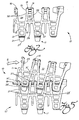
- FIG. 1 and 2 showing a single modular link assembly 10 comprised of a plurality of individual links 11, which can be either formed integrally together in any suitable number, or as separate links 11.
- the assembly 10, and more specifically the individual links 11, establish a closely interdigitating conveying surface, while at the same time assuring that the links have exceptionally smooth interaction with each other.
- a more efficient modular link conveyor for moving articles or products along a straight or curved conveying path is obtained.
- Each individual link 11 includes a leading apex 13 and a pair of legs 15 extending at an acute angle therefrom.
- the legs 15 terminate at a trailing apex 16.
- a plurality of transverse connectors 18 are provided to interconnect and retain the module assembly 10 together, thereby forming a complete modular link conveyor.
- the leading apexes 13 of the links 11 include a transversely oriented slot 17 for receiving the connectors 18.
- the trailing apex 16 includes a transverse hole 19 for also receiving the connectors 18.
- the slots 17/holes 19 are co-axial such that each connector 18 passes freely through all aligned holes 19 and slots 17.
- the links 11 further include a forwardly extending tongue 21 projecting from the leading apex 13.
- the tongue 21 has a top side 23 and a bottom side 25 which meet at a terminal apex 27.
- the tongue 21 is tapered in the horizontal plane. More specifically, the tongue 21 tapers from the leading apex 13 downward to the terminal apex 27.
- the assembly 10 further includes a forwardly projecting finger 29 positioned between adjoining links 11.
- the trailing apex 16 includes an open groove 31 in axial alignment with the finger 29.
- the open groove 31 exposes the hole 19, and more specifically exposes the connectors 18 which pass transversely through the holes of trailing apex 16.
- This open groove concept allows for visual inspection of the connectors 18 for ordinary wear. Deleterious mechanical wear, or even failure following extended periods of use, can thus be better avoided.
- the connectors 18 may be accessed via open groove 31 for other purposes such as cleaning, an important concern for modular link conveyors used in, for example, food processing industries.
- a plurality of laterally and longitudinally repeating modular assemblies 10, and more specifically a plurality of repeating links 11, are assembled to create a closely interdigitating conveying surface.
- the forwardly extending tongue and the forwardly projecting finger eliminate undesirable and unnecessary gaps or openings which may exist in the conveying surface.
- the tongue and finger concepts are important improvements resulting in an interdigitating grid surface for conveying, while at the same time maintaining the basic open design for cleaning, and with the attendant advantage of being lighter in weight and generally lower in cost.
- Such individual features, or the combination are previously unknown in the relevant art.
- tongue 21 and finger 29 form particularly important components in establishing a closely interdigitating conveying surface while maneuvering through a turn.
- leading apex 13 and tongue 21 can move all the way forward into the open space 33' and essentially close it.
- top side 23 of tongue 21 being tapered downward, any small articles or objects of like type that happen to be present in open space 33' are lifted upward and out of the open space.
- the modules 10, 10' are allowed to fully compress together as intended, enabling the conveyor to properly negotiate the turn. Without the tapered tongue 21, any foreign objects present in open space 33' could merely become jammed between modules 10, 10' during compression, causing disruption in the turning operation of the conveyor assembly.
- the forwardly projecting finger 29 also moves forward during compression so as to aid in dislodging any foreign objects which may be present in the opening 35. This further prevents small articles or other objects from falling into or becoming jammed in opening 35' during turning of the conveyor. Additionally, the positioning of finger 29 also provides for more structural support of the articles being transported on the conveyor over the openings 35, 35'.
- the modular link assembly 10 further include two-way angled undercuts 37, 38 on legs 15 adjacent both the leading apex 13 and the trailing apex 16, respectively.
- the undercuts 37, 38 provide increased cooperation between the closely interconnected links 11 when the modules 10, 10' are maneuvering through curves and bends in the flow path.
- the angled undercut 37 adjacent the leading apex 13 provides increased pivoting area for trailing apex 16' of the next forward link.
- the angled undercut 38' adjacent the trailing apex 16' provides increased pivoting area for the leading apex 13 and the tongue 21.
- the undercuts 37, 38 operate in two ways, that is in either a right or left turn.
- the assemblies 10 include a side fin 39 spanning the undercut 38 adjacent the trailing apex 16.
- the side fin 39 engages the inside surface forming the slot 17 which passes through the leading apex 13.
- the side fin 39 thus serves as a means for helping guide the links 11 through the bends or curves.
- the modular link conveyor assemblies 10, and more specifically the links 11, are capable of establishing a close interdigitating grid conveying surface.
- the tongue 21 and the finger 29 work in cooperation to eliminate any undesirable or unnecessary openings or gaps in the conveying surface. This minimizes the possibility of small articles or other objects present on or near the conveying surface from falling into or becoming jammed in the openings/gaps and disrupting the operation of the conveyor.
- the tongue 21 occupies opening 33, and with its tapered top side 23 is capable of lifting upward any article or foreign object inadvertently present.
- finger 29 dislodges any article or foreign object present in opening 35.
- the angled undercuts 37, 38 and the side fin 39 compliment the action of the tongue 21 and finger 29 by providing a guiding action to assure that the conveyor is able to traverse curves and bends in an efficient and smooth manner.
- the concepts of the present invention cooperatively work together in an unusually exceptional manner so as to create an all around proper functioning and efficient modular link conveyor.
Landscapes
- Engineering & Computer Science (AREA)
- Mechanical Engineering (AREA)
- Chain Conveyers (AREA)
- Escalators And Moving Walkways (AREA)
- Handcart (AREA)
- Cooling, Air Intake And Gas Exhaust, And Fuel Tank Arrangements In Propulsion Units (AREA)
- Seal Device For Vehicle (AREA)
Claims (13)
- Modulgliedförderer zum Bewegen von Gegenständen längs einer Bahn- mit einer Vielzahl von Modulgliedanordnungen (10), die eine Förderfläche mit einer Vielzahl von seitlich und in Längsrichtung angeordneten, sich wiederholenden Gliedern (11) und durch fingerartiges Ineinandergreifen ein Gitter bilden, wobei-- jedes der Glieder (11) wenigstens einen vorderen Scheitelteil (13) und zwei Schenkel (15) aufweist, die sich von ihm aus unter Bildung eines offenen Raums (33) zwischen ihnen erstrecken,-- der vordere Scheitelteil (13) weiterhin einen Schlitz (17) hat, der quer im Wesentlichen über die ganze Breite der Glieder (11) hindurchgeht,-- die Schenkel (15) weiterhin in einem hinteren Scheitelteil (16) enden und-- jeder hintere Scheitelteil (16) ein Loch (19) hat, das quer durch ihn hindurchgeht, und- mit einer Vielzahl von Querverbindungseinrichtungen (18), die durch die Schlitze (17) und die Löcher (19) hindurchgehen, um die sich in Längsrichtung wiederholenden Modulglieder (11) zusammenzuschließen,dadurch gekennzeichnet,- dass wenigstens eines der Glieder (11) weiterhin eine sich nach vorne erstreckende Zunge (21) hat, die sich in der horizontalen Ebene verjüngt und von dem vorderen Scheitelteil (13) vorsteht, und- dass die Zunge (21) eine Oberseite (23) und eine Unterseite (25) hat, die sich in einem Endscheitelteil (27) treffen,- wodurch eine Längskompression der Förderfläche dazu führt, dass die Zunge (21) den offenen Raum (33) zwischen den vorderen Scheitelteilen (16) des nächsten vorderen Glieds (11) in dem durch fingerartiges Ineinandergreifen gebildeten Gitter im Wesentlichen füllt, so dass ein in dem Raum (33) vorhandener Fremdgegenstand durch Heben freigesetzt wird, wenn sich die Zunge (21) in den Raum (33) nach vorne bewegt.
- Modulgliedförderer nach Anspruch 1, bei welchem die aneinandergrenzenden Schenkel (15) der sich seitlich wiederholenden Glieder (11) angrenzend an den vorderen Scheitelteil (16) eine Öffnung (35) bilden.
- Modulgliedförderer nach Anspruch 2, bei welchem jede der Modulgliedanordnungen (10) weiterhin einen nach vorne vorstehenden Finger (29) aufweist, der zwischen den sich seitlich wiederholenden Gliedern (11) in dem durch fingerartiges Ineinandergreifen gebildeten Gitter angeordnet ist, wodurch die Längskompression der Förderfläche dazu führt, dass der Finger (29) die Öffnung (35) zwischen den Schenkeln (15, 15') im Wesentlichen ausfüllt, so dass ein in der Öffnung (35) vorhandener Fremdgegenstand entfernt wird, wenn sich der Finger (29) in die Öffnung nach vorne bewegt.
- Modulgliedförderer nach Anspruch 2, bei welchem der hintere Scheitelteil (16) angrenzend an die Öffnung (35) eine offene Nut (31) hat, die das durch den hinteren Scheitelteil (16) hindurchgehende Loch (19) freisetzt, um eine Reinigung und Inspektion zu ermöglichen, wobei die Längskompression dazu führt, dass sich der Finger (29) durch die offene Nut (21) und in die Öffnung (35) erstreckt.
- Modulgliedförderer nach Anspruch 4, bei welchem die Schenkel (15) sowohl angrenzend an den vorderen Scheitelteil (13) als auch an den hinteren Scheitelteil (16) Winkelhinterschneidungen (37, 38) für ein verbessertes Zusammenpassen zwischen den Gliedern (11) während der Längskompression aufweisen.
- Modulgliedförderer nach Anspruch 5, welcher weiterhin eine Seitenrippe (39) aufweist, die die Winkelhinterschneidung (38) angrenzend an den hinteren Scheitelteil (16) für einen Eingriff mit dem Schlitz (17) überspannt, um so die Glieder (11) während der Längskompression zu führen.
- Modulgliedförderer nach Anspruch 1, bei welchem die Schenkel (15) sowohl angrenzend an den vorderen Scheitelteil (13) als auch an den hinteren Scheiteilteil (16) eine Winkelhinterschneidung (37, 38) für ein verbessertes Zusammenpassen zwischen den Gliedern (11) während der Längskompression aufweisen.
- Modulgliedförderer nach Anspruch 7, welcher weiterhin eine Seitenrippe (39) aufweist, die die Winkelhinterschneidung (38) angrenzend an den hinteren Scheitelteil (16) für einen Eingriff mit dem Schlitz (17) überspannt, um so die Glieder (11) während der Längskompression zu führen.
- Modulgliedförderer nach Anspruch 1, bei welchem die Oberseite (23) der Zunge (21) sich von dem vorderen Scheitelteil (13) des Glieds (11) aus nach unten zu dem Endscheitelteil (27) verjüngt.
- Modulgliedförderer zum Bewegen von Gegenständen längs einer Bahn- mit einer Vielzahl von Modulgliedanordnungen (10), die eine Förderfläche mit einer Vielzahl von seitlich und in Längsrichtung angeordneten, sich wiederholenden Gliedern (11) und durch fingerartiges Ineinandergreifen ein Gitter bilden, wobei-- jedes der Glieder (11) wenigstens einen vorderen Scheitelteil (13) und zwei sich davon aus erstreckende Schenkel (15) aufweist,-- der vordere Scheitelteil (13) weiterhin einen Schlitz (17) hat, der quer im Wesentlichen über die ganze Breite der Glieder (11) hindurchgeht,-- die Schenkel (15) weiterhin in einem hinteren Scheitelteil (16) enden,-- jeder hintere Scheitelteil (16) ein Loch (19) hat, das quer durch ihn hindurchgeht, und-- benachbarte Schenkel (15) der sich seitlich wiederholenden Glieder (11) angrenzend an den vorderen Scheitelteil (16) eine Öffnung (35) bilden, und- mit einer Vielzahl von Querverbindungseinrichtungen (18), die durch die Schlitze (17) und die Löcher (19) hindurchgehen, um die sich in Längsrichtung wiederholenden Modulglieder (11) zusammenzuschließen,dadurch gekennzeichnet,- dass wenigstens eines der Glieder (11) weiterhin einen nach vorne vorstehenden Finger (29) aufweist, der zwischen den sich seitlich wiederholenden Gliedern (11) in dem durch fingerartiges Ineinandergreifen gebildeten Gitter angeordnet ist, wodurch die Längskompression der Förderfläche dazu führt, dass der Finger (29) die Öffnung (35) zwischen den Schenkeln (15) im Wesentlichen ausfüllt, so dass ein in der Öffnung (35) vorhandener Fremdgegenstand entfernt wird, wenn sich der Finger (29) in die Öffnung (35) nach vorne bewegt.
- Modulgliedförderer nach Anspruch 10, bei welchem der hintere Scheitelteil (16) angrenzend an die Öffnung (35) eine offene Nut (31) hat, die das durch den hinteren Scheitelteil (16) hindurchgehende Loch (19) freisetzt, um eine Reinigung und Inspektion zu ermöglichen, wobei die Längskompression dazu führt, dass sich der Finger (29) durch die offene Nut (21) und in die Öffnung (35) erstreckt.
- Modulgliedförderer nach Anspruch 10, bei welchem die Schenkel (15) sowohl angrenzend an den vorderen Scheitelteil (13) als auch an den hinteren Scheitelteil (16) Winkelhinterschneidungen (37, 38) für ein verbessertes Zusammenpassen zwischen den Gliedern (11) während der Längskompression aufweisen.
- Modulgliedförderer nach Anspruch 12, welcher weiterhin eine Seitenrippe (39) aufweist, die die Winkelhinterschneidung (38) angrenzend an den hinteren Scheitelteil (16) für einen Eingriff mit dem Schlitz (17) überspannt, um so die Glieder (11) während der Längskompression zu führen.
Applications Claiming Priority (3)
| Application Number | Priority Date | Filing Date | Title |
|---|---|---|---|
| US08/660,551 US5690210A (en) | 1996-06-10 | 1996-06-10 | Modular link conveyor with interdigitating grid |
| PCT/US1997/007747 WO1997047539A1 (en) | 1996-06-10 | 1997-04-28 | Modular link conveyor with interdigitating grid |
| US660551 | 2000-09-11 |
Publications (3)
| Publication Number | Publication Date |
|---|---|
| EP0907591A1 EP0907591A1 (de) | 1999-04-14 |
| EP0907591A4 EP0907591A4 (de) | 2001-04-11 |
| EP0907591B1 true EP0907591B1 (de) | 2007-06-27 |
Family
ID=24649985
Family Applications (1)
| Application Number | Title | Priority Date | Filing Date |
|---|---|---|---|
| EP97924613A Expired - Lifetime EP0907591B1 (de) | 1996-06-10 | 1997-04-28 | Modulares gliederförderband mit ineinandergreifendem gitter |
Country Status (8)
| Country | Link |
|---|---|
| US (1) | US5690210A (de) |
| EP (1) | EP0907591B1 (de) |
| AT (1) | ATE365693T1 (de) |
| AU (1) | AU2999497A (de) |
| CA (1) | CA2257868C (de) |
| DE (1) | DE69737860T2 (de) |
| DK (1) | DK0907591T3 (de) |
| WO (1) | WO1997047539A1 (de) |
Cited By (1)
| Publication number | Priority date | Publication date | Assignee | Title |
|---|---|---|---|---|
| US9969556B2 (en) | 2013-11-07 | 2018-05-15 | Ammerall Beltech Modular A/S | Conveyor belt module |
Families Citing this family (18)
| Publication number | Priority date | Publication date | Assignee | Title |
|---|---|---|---|---|
| US5797820A (en) * | 1995-09-22 | 1998-08-25 | Yamakyu Chain Co., Ltd. | Slat band chain and sprocket |
| US6223889B1 (en) | 1996-06-10 | 2001-05-01 | Span Tech Llc | Modular link conveyor with interdigitating grid and interleaving side wings |
| US6041917A (en) * | 1996-06-10 | 2000-03-28 | Span Tech Llc | Modular link conveyor with interdigitating grid and open apex |
| NL1003929C2 (nl) * | 1996-08-30 | 1998-03-04 | Jonge Poerink Bv | Transportband en daarvan voorziene transportinrichting. |
| USD427898S (en) * | 1997-04-02 | 2000-07-11 | Sinapore Technologies Automotive Limited | Tracked link body |
| NL1008743C2 (nl) * | 1998-03-30 | 1999-10-01 | Mcc Nederland | Transportmat. |
| ES2183527T3 (es) * | 1998-03-30 | 2003-03-16 | Mcc Nederland | Estera transportadora. |
| US6330941B1 (en) | 2000-05-25 | 2001-12-18 | Habasit Ag | Radius conveyor belt |
| US6305530B1 (en) | 2000-05-30 | 2001-10-23 | Habasit Ag | Module for a modular conveying belt |
| US6357581B1 (en) | 2000-07-19 | 2002-03-19 | Habasit Ag | Modular radius conveyor belt |
| US6612426B1 (en) | 2000-10-24 | 2003-09-02 | Autopak Engineering Corporation | Conveyor belt assembly |
| US6705460B2 (en) * | 2002-04-23 | 2004-03-16 | Laitram L.L.C. | Modular conveyor belt |
| US7293644B2 (en) * | 2004-12-06 | 2007-11-13 | Rexnord Industries, Llc | Side-flexing conveyor chain |
| CN104995110B (zh) | 2012-10-25 | 2017-08-01 | 雷勃电气美国公司 | 控制传送器的轨道磨损的设备和方法 |
| EP2925643A4 (de) | 2012-11-29 | 2017-01-04 | Regal Beloit America, Inc. | Förderer mit seitlicher biegung |
| CN105164029B (zh) * | 2013-06-28 | 2016-12-07 | 株式会社椿本链条 | 传送带以及带构成部件 |
| CA2905156C (en) * | 2014-11-27 | 2024-04-30 | Martin S. Niles | Conductor cover applicator |
| USD804137S1 (en) * | 2016-02-23 | 2017-11-28 | Span Tech Llc | Conveyor link |
Family Cites Families (16)
| Publication number | Priority date | Publication date | Assignee | Title |
|---|---|---|---|---|
| US3880276A (en) * | 1973-07-09 | 1975-04-29 | Iii George Howard Willett | Conveyor chain |
| US3881593A (en) * | 1974-01-28 | 1975-05-06 | Norton Co | Chain conveyor link and attachment therefor |
| US4993544A (en) * | 1989-01-13 | 1991-02-19 | Cambridge Wire Cloth Company | Plastic modular conveyor belts and modules therefor |
| US4953693A (en) * | 1989-01-23 | 1990-09-04 | Span Tech Corporation | Modular link conveyor system |
| DK162348C (da) * | 1989-07-20 | 1992-03-09 | Joergen Draebel | Kaedeled til en sideboejelig transportkaede |
| US5181601A (en) * | 1990-10-09 | 1993-01-26 | Palmaer K V | Plastic conveyor belt with integral sideplate |
| US5224583A (en) * | 1990-10-09 | 1993-07-06 | Palmaer K V | Low back pressure plastic conveyor |
| US5197591A (en) * | 1992-02-11 | 1993-03-30 | Ashworth Bros., Inc. | Replaceable snap-on modular overlay for rod and link turn-curve conveyor belts |
| US5174439A (en) * | 1991-07-03 | 1992-12-29 | Cambridge Wire Cloth Company | Modular plastic turn belt conveyor system, module, belt and drive therefor |
| IT226681Z2 (it) * | 1992-06-10 | 1997-07-01 | Regina Sud | Maglia di trasportatore a catena con dispositivo di blocco del perno |
| US5215185A (en) * | 1992-09-08 | 1993-06-01 | Rexnord Corporation | Breakable molded plastic links for forming conveyor chain |
| US5335768A (en) * | 1993-03-12 | 1994-08-09 | Rexnord Corporation | Conveyor chain assembly |
| US5318169A (en) * | 1993-05-27 | 1994-06-07 | William G. Faulkner | Spiral conveyor belt |
| US5431275A (en) * | 1993-05-27 | 1995-07-11 | William G. Faulkner | Conveyor belt with rotatable tapered link shift |
| US5489020A (en) * | 1994-06-08 | 1996-02-06 | Tekno, Inc. | Smooth-driving conveyor chain |
| US5497874A (en) * | 1994-06-20 | 1996-03-12 | Span Tech Corporation | Article engaging insert for modular link conveyor |
-
1996
- 1996-06-10 US US08/660,551 patent/US5690210A/en not_active Expired - Lifetime
-
1997
- 1997-04-28 AU AU29994/97A patent/AU2999497A/en not_active Abandoned
- 1997-04-28 CA CA002257868A patent/CA2257868C/en not_active Expired - Fee Related
- 1997-04-28 EP EP97924613A patent/EP0907591B1/de not_active Expired - Lifetime
- 1997-04-28 AT AT97924613T patent/ATE365693T1/de not_active IP Right Cessation
- 1997-04-28 WO PCT/US1997/007747 patent/WO1997047539A1/en not_active Ceased
- 1997-04-28 DK DK97924613T patent/DK0907591T3/da active
- 1997-04-28 DE DE69737860T patent/DE69737860T2/de not_active Expired - Fee Related
Cited By (1)
| Publication number | Priority date | Publication date | Assignee | Title |
|---|---|---|---|---|
| US9969556B2 (en) | 2013-11-07 | 2018-05-15 | Ammerall Beltech Modular A/S | Conveyor belt module |
Also Published As
| Publication number | Publication date |
|---|---|
| US5690210A (en) | 1997-11-25 |
| DE69737860D1 (de) | 2007-08-09 |
| CA2257868C (en) | 2005-04-12 |
| EP0907591A4 (de) | 2001-04-11 |
| DK0907591T3 (da) | 2007-10-15 |
| WO1997047539A1 (en) | 1997-12-18 |
| ATE365693T1 (de) | 2007-07-15 |
| AU2999497A (en) | 1998-01-07 |
| EP0907591A1 (de) | 1999-04-14 |
| DE69737860T2 (de) | 2008-03-13 |
| CA2257868A1 (en) | 1997-12-18 |
Similar Documents
| Publication | Publication Date | Title |
|---|---|---|
| EP0907591B1 (de) | Modulares gliederförderband mit ineinandergreifendem gitter | |
| US6223889B1 (en) | Modular link conveyor with interdigitating grid and interleaving side wings | |
| US6041917A (en) | Modular link conveyor with interdigitating grid and open apex | |
| KR100347992B1 (ko) | 교차컨베이어사이에서물품을운송하기위한방향변경기구 | |
| EP1687221B1 (de) | Kunststoffförderbandmodule mit seitenschutz | |
| US5497874A (en) | Article engaging insert for modular link conveyor | |
| EP1300349B1 (de) | Modulares Förderband mit mittels Stiften befestigten Zusatzteilen | |
| EP1277676B1 (de) | Seitenteil mit Schnappverschluss für Bandförderermodule | |
| US7530455B2 (en) | Module with large open hinge for easy cleaning | |
| AU745176B2 (en) | Conveyor with hinge pin retention plug with snap fit | |
| EP0503333A1 (de) | Modulare Förderkette mit offener Gelenkbolzenkonstruktion | |
| US6725883B2 (en) | Flat top open hinge module | |
| EP2134632A1 (de) | Modulares band mit stangenlosem scharnier | |
| EP1270454A1 (de) | Förderbandmodul mit glattem Gitter | |
| CA2380139A1 (en) | Radious conveyor belt with structure for the prevention of pinched fingers | |
| US6604625B2 (en) | Operating modular conveyor belts with migrating hinge pins | |
| MXPA01007319A (en) | Modular link conveyor with interdigitating grid | |
| MXPA00005044A (en) | Modular link conveyor with interdigitating grid and open apex | |
| US20190023495A1 (en) | Split Fluid Jet Head and Manifold for Receipt of Split Fluid Jet Head |
Legal Events
| Date | Code | Title | Description |
|---|---|---|---|
| PUAI | Public reference made under article 153(3) epc to a published international application that has entered the european phase |
Free format text: ORIGINAL CODE: 0009012 |
|
| 17P | Request for examination filed |
Effective date: 19990104 |
|
| AK | Designated contracting states |
Kind code of ref document: A1 Designated state(s): AT BE CH DE DK ES FI FR GB GR IE IT LI LU MC NL PT SE |
|
| A4 | Supplementary search report drawn up and despatched |
Effective date: 20010227 |
|
| AK | Designated contracting states |
Kind code of ref document: A4 Designated state(s): AT BE CH DE DK ES FI FR GB GR IE IT LI LU MC NL PT SE |
|
| RAP1 | Party data changed (applicant data changed or rights of an application transferred) |
Owner name: SPAN TECH LLC |
|
| GRAP | Despatch of communication of intention to grant a patent |
Free format text: ORIGINAL CODE: EPIDOSNIGR1 |
|
| GRAS | Grant fee paid |
Free format text: ORIGINAL CODE: EPIDOSNIGR3 |
|
| GRAA | (expected) grant |
Free format text: ORIGINAL CODE: 0009210 |
|
| AK | Designated contracting states |
Kind code of ref document: B1 Designated state(s): AT BE CH DE DK ES FI FR GB GR IE IT LI LU MC NL PT SE |
|
| REG | Reference to a national code |
Ref country code: GB Ref legal event code: FG4D |
|
| REG | Reference to a national code |
Ref country code: CH Ref legal event code: EP |
|
| REG | Reference to a national code |
Ref country code: IE Ref legal event code: FG4D |
|
| REF | Corresponds to: |
Ref document number: 69737860 Country of ref document: DE Date of ref document: 20070809 Kind code of ref document: P |
|
| PG25 | Lapsed in a contracting state [announced via postgrant information from national office to epo] |
Ref country code: SE Free format text: LAPSE BECAUSE OF FAILURE TO SUBMIT A TRANSLATION OF THE DESCRIPTION OR TO PAY THE FEE WITHIN THE PRESCRIBED TIME-LIMIT Effective date: 20070927 |
|
| REG | Reference to a national code |
Ref country code: DK Ref legal event code: T3 |
|
| NLV1 | Nl: lapsed or annulled due to failure to fulfill the requirements of art. 29p and 29m of the patents act | ||
| ET | Fr: translation filed | ||
| REG | Reference to a national code |
Ref country code: CH Ref legal event code: PL |
|
| PG25 | Lapsed in a contracting state [announced via postgrant information from national office to epo] |
Ref country code: BE Free format text: LAPSE BECAUSE OF FAILURE TO SUBMIT A TRANSLATION OF THE DESCRIPTION OR TO PAY THE FEE WITHIN THE PRESCRIBED TIME-LIMIT Effective date: 20070627 |
|
| PG25 | Lapsed in a contracting state [announced via postgrant information from national office to epo] |
Ref country code: PT Free format text: LAPSE BECAUSE OF FAILURE TO SUBMIT A TRANSLATION OF THE DESCRIPTION OR TO PAY THE FEE WITHIN THE PRESCRIBED TIME-LIMIT Effective date: 20071127 Ref country code: NL Free format text: LAPSE BECAUSE OF FAILURE TO SUBMIT A TRANSLATION OF THE DESCRIPTION OR TO PAY THE FEE WITHIN THE PRESCRIBED TIME-LIMIT Effective date: 20070627 Ref country code: ES Free format text: LAPSE BECAUSE OF FAILURE TO SUBMIT A TRANSLATION OF THE DESCRIPTION OR TO PAY THE FEE WITHIN THE PRESCRIBED TIME-LIMIT Effective date: 20071008 |
|
| PG25 | Lapsed in a contracting state [announced via postgrant information from national office to epo] |
Ref country code: CH Free format text: LAPSE BECAUSE OF FAILURE TO SUBMIT A TRANSLATION OF THE DESCRIPTION OR TO PAY THE FEE WITHIN THE PRESCRIBED TIME-LIMIT Effective date: 20070627 Ref country code: LI Free format text: LAPSE BECAUSE OF FAILURE TO SUBMIT A TRANSLATION OF THE DESCRIPTION OR TO PAY THE FEE WITHIN THE PRESCRIBED TIME-LIMIT Effective date: 20070627 |
|
| PG25 | Lapsed in a contracting state [announced via postgrant information from national office to epo] |
Ref country code: IT Free format text: LAPSE BECAUSE OF FAILURE TO SUBMIT A TRANSLATION OF THE DESCRIPTION OR TO PAY THE FEE WITHIN THE PRESCRIBED TIME-LIMIT Effective date: 20070627 Ref country code: GR Free format text: LAPSE BECAUSE OF FAILURE TO SUBMIT A TRANSLATION OF THE DESCRIPTION OR TO PAY THE FEE WITHIN THE PRESCRIBED TIME-LIMIT Effective date: 20070928 |
|
| PGFP | Annual fee paid to national office [announced via postgrant information from national office to epo] |
Ref country code: DK Payment date: 20080314 Year of fee payment: 12 |
|
| PLBE | No opposition filed within time limit |
Free format text: ORIGINAL CODE: 0009261 |
|
| STAA | Information on the status of an ep patent application or granted ep patent |
Free format text: STATUS: NO OPPOSITION FILED WITHIN TIME LIMIT |
|
| PGFP | Annual fee paid to national office [announced via postgrant information from national office to epo] |
Ref country code: GB Payment date: 20080320 Year of fee payment: 12 |
|
| 26N | No opposition filed |
Effective date: 20080328 |
|
| PGFP | Annual fee paid to national office [announced via postgrant information from national office to epo] |
Ref country code: FR Payment date: 20080313 Year of fee payment: 12 Ref country code: DE Payment date: 20080320 Year of fee payment: 12 |
|
| PGFP | Annual fee paid to national office [announced via postgrant information from national office to epo] |
Ref country code: AT Payment date: 20080311 Year of fee payment: 12 |
|
| PG25 | Lapsed in a contracting state [announced via postgrant information from national office to epo] |
Ref country code: MC Free format text: LAPSE BECAUSE OF NON-PAYMENT OF DUE FEES Effective date: 20080430 |
|
| PG25 | Lapsed in a contracting state [announced via postgrant information from national office to epo] |
Ref country code: FI Free format text: LAPSE BECAUSE OF FAILURE TO SUBMIT A TRANSLATION OF THE DESCRIPTION OR TO PAY THE FEE WITHIN THE PRESCRIBED TIME-LIMIT Effective date: 20070627 |
|
| PG25 | Lapsed in a contracting state [announced via postgrant information from national office to epo] |
Ref country code: IE Free format text: LAPSE BECAUSE OF NON-PAYMENT OF DUE FEES Effective date: 20080428 |
|
| REG | Reference to a national code |
Ref country code: DK Ref legal event code: EBP |
|
| GBPC | Gb: european patent ceased through non-payment of renewal fee |
Effective date: 20090428 |
|
| REG | Reference to a national code |
Ref country code: FR Ref legal event code: ST Effective date: 20091231 |
|
| PG25 | Lapsed in a contracting state [announced via postgrant information from national office to epo] |
Ref country code: DE Free format text: LAPSE BECAUSE OF NON-PAYMENT OF DUE FEES Effective date: 20091103 Ref country code: AT Free format text: LAPSE BECAUSE OF NON-PAYMENT OF DUE FEES Effective date: 20090428 |
|
| PG25 | Lapsed in a contracting state [announced via postgrant information from national office to epo] |
Ref country code: GB Free format text: LAPSE BECAUSE OF NON-PAYMENT OF DUE FEES Effective date: 20090428 Ref country code: FR Free format text: LAPSE BECAUSE OF NON-PAYMENT OF DUE FEES Effective date: 20091222 Ref country code: DK Free format text: LAPSE BECAUSE OF NON-PAYMENT OF DUE FEES Effective date: 20090430 |
|
| PG25 | Lapsed in a contracting state [announced via postgrant information from national office to epo] |
Ref country code: LU Free format text: LAPSE BECAUSE OF NON-PAYMENT OF DUE FEES Effective date: 20080428 |