EP0907576B1 - Flat-top container with an opening fitment - Google Patents
Flat-top container with an opening fitment Download PDFInfo
- Publication number
- EP0907576B1 EP0907576B1 EP97920177A EP97920177A EP0907576B1 EP 0907576 B1 EP0907576 B1 EP 0907576B1 EP 97920177 A EP97920177 A EP 97920177A EP 97920177 A EP97920177 A EP 97920177A EP 0907576 B1 EP0907576 B1 EP 0907576B1
- Authority
- EP
- European Patent Office
- Prior art keywords
- container
- end sections
- sections
- fitment
- mandrel
- Prior art date
- Legal status (The legal status is an assumption and is not a legal conclusion. Google has not performed a legal analysis and makes no representation as to the accuracy of the status listed.)
- Expired - Lifetime
Links
- 241001270131 Agaricus moelleri Species 0.000 title abstract 2
- 239000011087 paperboard Substances 0.000 claims abstract description 20
- 238000004519 manufacturing process Methods 0.000 claims abstract description 8
- 238000007789 sealing Methods 0.000 claims description 16
- 238000004806 packaging method and process Methods 0.000 claims description 11
- 238000000034 method Methods 0.000 claims description 9
- 239000000758 substrate Substances 0.000 abstract description 10
- 238000010438 heat treatment Methods 0.000 description 10
- 230000007246 mechanism Effects 0.000 description 10
- 239000007788 liquid Substances 0.000 description 8
- 239000007789 gas Substances 0.000 description 5
- 239000002648 laminated material Substances 0.000 description 5
- 239000000463 material Substances 0.000 description 5
- 239000000047 product Substances 0.000 description 5
- 239000012815 thermoplastic material Substances 0.000 description 5
- 239000004033 plastic Substances 0.000 description 4
- 229920003023 plastic Polymers 0.000 description 4
- 210000000746 body region Anatomy 0.000 description 3
- 239000012263 liquid product Substances 0.000 description 3
- 229920001169 thermoplastic Polymers 0.000 description 3
- 239000004416 thermosoftening plastic Substances 0.000 description 3
- 230000004927 fusion Effects 0.000 description 2
- -1 wine Chemical compound 0.000 description 2
- 239000004698 Polyethylene Substances 0.000 description 1
- 238000004026 adhesive bonding Methods 0.000 description 1
- QVGXLLKOCUKJST-UHFFFAOYSA-N atomic oxygen Chemical compound [O] QVGXLLKOCUKJST-UHFFFAOYSA-N 0.000 description 1
- 238000005452 bending Methods 0.000 description 1
- 235000013361 beverage Nutrition 0.000 description 1
- 230000015572 biosynthetic process Effects 0.000 description 1
- 239000000969 carrier Substances 0.000 description 1
- 239000011248 coating agent Substances 0.000 description 1
- 238000000576 coating method Methods 0.000 description 1
- 238000001816 cooling Methods 0.000 description 1
- 230000000593 degrading effect Effects 0.000 description 1
- 230000001419 dependent effect Effects 0.000 description 1
- 238000006073 displacement reaction Methods 0.000 description 1
- 238000009826 distribution Methods 0.000 description 1
- 235000011389 fruit/vegetable juice Nutrition 0.000 description 1
- 230000005484 gravity Effects 0.000 description 1
- 238000001746 injection moulding Methods 0.000 description 1
- 235000013336 milk Nutrition 0.000 description 1
- 239000008267 milk Substances 0.000 description 1
- 210000004080 milk Anatomy 0.000 description 1
- 230000004048 modification Effects 0.000 description 1
- 238000012986 modification Methods 0.000 description 1
- 235000015205 orange juice Nutrition 0.000 description 1
- 239000001301 oxygen Substances 0.000 description 1
- 229910052760 oxygen Inorganic materials 0.000 description 1
- 239000005022 packaging material Substances 0.000 description 1
- 229920000573 polyethylene Polymers 0.000 description 1
- 229920000642 polymer Polymers 0.000 description 1
- 239000002861 polymer material Substances 0.000 description 1
- 239000000843 powder Substances 0.000 description 1
- 230000000717 retained effect Effects 0.000 description 1
- 238000003860 storage Methods 0.000 description 1
- 230000001360 synchronised effect Effects 0.000 description 1
Images


Classifications
-
- B—PERFORMING OPERATIONS; TRANSPORTING
- B65—CONVEYING; PACKING; STORING; HANDLING THIN OR FILAMENTARY MATERIAL
- B65D—CONTAINERS FOR STORAGE OR TRANSPORT OF ARTICLES OR MATERIALS, e.g. BAGS, BARRELS, BOTTLES, BOXES, CANS, CARTONS, CRATES, DRUMS, JARS, TANKS, HOPPERS, FORWARDING CONTAINERS; ACCESSORIES, CLOSURES, OR FITTINGS THEREFOR; PACKAGING ELEMENTS; PACKAGES
- B65D5/00—Rigid or semi-rigid containers of polygonal cross-section, e.g. boxes, cartons or trays, formed by folding or erecting one or more blanks made of paper
- B65D5/42—Details of containers or of foldable or erectable container blanks
- B65D5/72—Contents-dispensing means
- B65D5/74—Spouts
- B65D5/746—Spouts formed separately from the container
-
- B—PERFORMING OPERATIONS; TRANSPORTING
- B31—MAKING ARTICLES OF PAPER, CARDBOARD OR MATERIAL WORKED IN A MANNER ANALOGOUS TO PAPER; WORKING PAPER, CARDBOARD OR MATERIAL WORKED IN A MANNER ANALOGOUS TO PAPER
- B31B—MAKING CONTAINERS OF PAPER, CARDBOARD OR MATERIAL WORKED IN A MANNER ANALOGOUS TO PAPER
- B31B50/00—Making rigid or semi-rigid containers, e.g. boxes or cartons
- B31B50/74—Auxiliary operations
- B31B50/81—Forming or attaching accessories, e.g. opening devices, closures or tear strings
- B31B50/84—Forming or attaching means for filling or dispensing contents, e.g. valves or spouts
-
- B—PERFORMING OPERATIONS; TRANSPORTING
- B31—MAKING ARTICLES OF PAPER, CARDBOARD OR MATERIAL WORKED IN A MANNER ANALOGOUS TO PAPER; WORKING PAPER, CARDBOARD OR MATERIAL WORKED IN A MANNER ANALOGOUS TO PAPER
- B31B—MAKING CONTAINERS OF PAPER, CARDBOARD OR MATERIAL WORKED IN A MANNER ANALOGOUS TO PAPER
- B31B50/00—Making rigid or semi-rigid containers, e.g. boxes or cartons
- B31B50/26—Folding sheets, blanks or webs
- B31B50/28—Folding sheets, blanks or webs around mandrels, e.g. for forming bottoms
Definitions
- the present invention generally relates to an improved container and, more specifically, to a paperboard-based container having an opening fitment, wherein the container includes hermetically sealed upper and lower ends that prevent wicking of liquid products into the paperboard substrate of the container.
- the liquids may include beverages, such as milk and juice.
- the containers may be formed from blanks or sheets made of a variety of laminate materials having a substrate such as paperboard, strawboard, pasteboard, cardboard and the like.
- the substrate material is laminated or coated with a thermoplastic or a similar liquid resistant coating to enable the container to retain liquids.
- the blanks are folded into a variety of container cross-sections, such as tubular, rectangular, square and the like.
- thermoplastic material may be shaped and sealed to the container side walls by using an injection molding process.
- the upper end may be formed from a soft plastic strip placed over the end of the side walls and then heated and thermoformed to the side walls.
- the thermoform process is effected within an end mold such that the resultant plastic end cap conforms in shape to that of the mold.
- the end cap may be formed with an integral end cap which receives a plug.
- the end cap may be threaded to receive a screw cap.
- thermoformed plastic end cap may be relatively difficult to manufacture and requires substantial tooling which is added to existing packaging machine.
- the resultant container may also be more expensive than a similarly shaped container which is entirely formed of the paperboard -based laminate material.
- Gable-top containers either flattened or erect, are also quite popular and are an alternative to the thermoformed-top container discussed above.
- the flattened and erect gable shaped ends may include separate opening arrangements, such as a screw cap type fitment or the like. Exemplary opening arrangements are disclosed in USP 5,248,054 ; USP 2,980,304 ; and USP 2,432,462 .
- the conventional gabled-top containers may also experienced limitations that are dependent upon the circumstances. Gable-shaped ends require more material than flat ends, even though gable shaped and flat ended containers provide the same storage volume. In addition, it is often difficult to manufacture a gable shaped container with a spout and cap. When adding the spout to the gable shaped container, it was added to the erected blank prior to forming the gable. Once the spout is added, the ends of the are folded, heated, and pressed together to form the familiar sealed fin of the gabled-top structure. The spout, however, must be located remote from the fin in order to avoid interference by the spout with the manufacturing equipment which heat seals the fin panels. Such remote placement of the cap often locates the cap in an awkward position to one side of the container.
- the present invention is directed at a paperboard-based container formed from a blank folded along fold lines, the container having side panels with upper and lower end sections, and the upper end sections defining inner and outer opposed pairs with cut-outs, folded towards one another, wherein the cut-outs combine to define an aperture which receives a fitment sealed to the upper end sections around the aperture.
- each of the inner opposed upper end section pairs is divided along fold lines into a middle region and lateral side regions, and folded under the outer pairs with each side region between a respective middle region and a respective outer end section, to form a flat container top.
- a typical container according to the invention includes a rectanguloid sleeve having upper end sections joined at fold lines with side walls.
- the upper end sections are divided into inner and outer opposed pairs which are folded toward one another in an overlapping manner to form a generally flat end for the container.
- Each of the inner and outer opposed sections includes a cutout. When the upper end sections are folded in the manner described above to form the flat end, the cutouts define an aperture having edges that include exposed paperboard substrate.
- Each of the inner pair of opposed end sections are divided along fold lines into a middle region and laterally opposed side regions. The laterally opposed side regions are folded onto the middle region and are sandwiched between the middle region and the outer pair of opposed sections when folded to form the container top.
- One of the outer pair of opposed upper end sections is longer than the other so that the longer outer end section overlaps exterior to the shorter of the outer pair of opposed upper end sections.
- An opening fitment is disposed through the aperture and includes a flange at the interior of the container. The flange covers the exposed edges of the aperture.
- the fitment is preferably a resealable cover, such as a resealable screw-type spout and cap or the like, but may also be in the form of a generally flattened disc.
- the containers of the invention facilitate the creation of an hermetically sealed paperboard-based container which can be manufactured with a reduced amount of packaging material per unit volume when compared to other selected container types.
- the foregoing container design may also be exploited with a minimum amount of retooling of the manufacturing equipment.
- the invention also provides a method of fabricating a container from a blank in a packaging machine, the blank having fold lines defining side panels with upper and lower end sections, the upper end sections being formed with cut-outs, wherein each of the inner opposed upper end section pairs is divided along fold lines into a middle region and lateral side regions, which method comprises folding the blank around fold lines to form a tubular body and fitting the body around a mandrel with the upper end sections of the side panels projecting beyond the top of the mandrel; and folding end sealing the upper end sections to close the upper end of the container Around an aperture defined by the juxtaposition of the cut-outs, with the lateral side regions of the inner upper sections under the outer pairs and closed upper end conforming to the contour of the mandrel top; installing and sealing a fitment in the aperture; and closing and sealing the lower end sections of the container.
- a packaging machine for fabricating a container from a blank of the kind described above, comprises means for folding a said blank around fold lines therein to form a tubular body, and for fitting such body on a mandrel with its said upper end sections projecting beyond the top of the mandrel; a device for folding and sealing the upper end sections of said body to close the upper end thereof with the lateral side regions between a respective middle region and a respective outer end section, and with the closed end conforming to the contour of the mandrel top; and means for installing a fitment in an aperture formed in said body upper end.
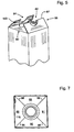
- Fig. 1 generally illustrates a perspective view of a container formed according to the present invention (generally denoted by reference numeral 2).
- the container 2 when completed, may include any desire cross-sectional shape, such as a rectangular shape, circular shape, square shape and the like.
- the container 2 is formed in a rectangular shape with side walls 4, a top 6 and a bottom 8.
- the top 6 may include a screw cap assembly 10 or the like that includes an opening fitment and corresponding cap.
- a flat blank 12 is illustrated which is utilized to form the container 2 of Fig. 1.
- the blank 12 is preferably formed from a laminate material that includes a paperboard substrate disposed between two or more liquid resistant layers, such as layers of polyethylene.
- the blank 12 includes four panel sections 14 divided from one another along fold lines 16.
- a side overlapping section 18 may be provided integrally along one side of one panel 14 to be used to form the side seam 15 shown in Fig. 3.
- the side overlapping section 18 is separated from the panel 14 by fold line 20.
- the side overlapping section 18 is folded inward along line 20 to lie adjacent to the inner surface 22 of the panel 14.
- the overlapping section 18 includes an edge 24 extending along its length.
- a side lip 26 is folded along the length of the overlapping section 18 in order to sandwich the lip 26 between the section 18 and the side panel 14 with the side edge 24 isolated from the interior of the container. By folding the lip 26 in this manner, the side edge 24 is not exposed to the liquid product within the container.
- the panels 14 include side wall portions 28 which define the sidewalls 4 of the formed container 2.
- the panels 14 also include upper and lower end sections 32 and 30.
- the end sections 30 and 32 are separated from the side wall portions 28 via fold lines 34 and 36.
- the upper and lower end sections 30 and 32 also include outer edges 38 and 40.
- the paperboard substrate of the laminate material is exposed along edges 38, 40 and 24.
- the end sections 30 cooperate, when folded upon one another, to define the bottom 8 of the container 2, while the end sections 32 cooperate, when folded, to form the top 6.
- the lower end sections 30 include an inner pair of end sections 42 and 44 and an outer pair of end sections 58 and 60.
- the upper end sections 32 include an inner pair of end sections 80 and 82 and an outer pair of end sections 84 and 86. As illustrated, the inner pair of end sections 42 and 44 of the lower end sections 30 and the inner pair of end sections 80 and 82 of the upper end sections 32 are divided from their respective side panels by curved fold lines 36.
- the lower end sections 42 and 44 are further segmented along fold lines 46 and 48 to define middle regions 50 and 52 and laterally disposed side or ear regions 54 and 56.
- the outer end section 58 includes an outermost flap 62 which, as will be shown in connection with FIG. 4, overlaps the seal formed by the sections 30 across the bottom 8 of the container.
- the end sections 42, 44 and 60 include outer lips 43, 45 and 61, respectively, which are covered by the flap 62.
- the inner pair of opposed end sections 42 and 44 are folded inward until lips 43 and 45 intersect proximate the center of the bottom 8.
- the outer pair of end sections 58 and 60 are folded inward until the lips 61 and 62 join.
- the ear regions 54 and 56 fold along lines 46 and 48 until overlapping the corresponding middle regions 50 and 52.
- the ear regions 54 and 56 are sandwiched between corresponding middle regions 50 and 52 and corresponding outer end sections 58 and 60.
- Fig. 4 illustrates the final folding of the lower end sections 30 in the proper relationships.
- the outer end sections 58 and 60 are folded (as explained below) to join at a seam 59.
- the lip 61 is folded outward along line 63 away from the interior of the container to isolate the edge 38 from the content of the container.
- the seam 59 resides in a recess thereby providing a generally flattened and stable seating surface for the container. Further details concerning the use of such curved fold lines are described in U.S. Patent No. 5,474,232, issued December 12, 1995 , and entitled "Gable Top Carton and Carton Blank Having Curved Side Creases", which is hereby incorporated by reference.
- the upper end sections 32 include an inner pair of end sections 80 and 82 and an outer pair of end sections 84 and 86.
- the end sections 80 and 82 each include middle regions 88 and 90 formed integrally with corresponding laterally disposed ear regions 92 and 94.
- the ear regions 92 and 94 are separated from corresponding body regions 88 and 90 via fold lines 96 and 98.
- one or more of the end sections 30 may include an overlap strip, such as strip 100 upon end section 84.
- the end sections 80-86 further include arcuate cutouts 102, 104, 106 and 108, respectively.
- the cutouts 102-106 combine, as explained below, to form an aperture through the top of the container which ultimately receives the opening fitment.
- FIG. 5 Folding of the top 6 of the container 2 is illustrated in Fig. 5. As shown, the top is formed by folding end sections 80 and 82 inward until outer tips 81 and 83 (Fig. 4) substantially adjoin one another. Thereafter, end sections 84 and 86 are folded inward until the overlap 100 overlaps the edge 40 of section 86. During this folding operation, the ear regions 92 and 94 are folded inward upon corresponding body regions 88 and 90, respectively, about corresponding fold lines 96 and 98. When folded in this manner, the ear regions 92 and 94 are sandwiched between corresponding middle regions 88 and 90 and adjacent end sections 84 and 86.
- the cap assembly 10 is inserted through the aperture 112 defined by the cutouts outward from the interior of the container through the opening 112 formed when the arcuate cutouts 102-108 join one another.
- the cap assembly 10 includes a fitment 114 with a circular base flange 116 and tubular stem 117 projecting outward through the opening 112.
- the flange 116 includes an upper sealing face 119 which is securely sealed against the interior surfaces 121 of the upper end sections 80, 82, 84 and 86 proximate the opening 112.
- the fitment 114 seals and isolates the edges 103, 105, 107 and 109 of the cutouts 102, 104, 106 and 108 from the interior of the container.
- the stem 117 may include.threads 122 which receive a corresponding threaded cap 124.
- the base flange 116 covers a center region of the end sections 80, 82, 84 and 86 to cover any portions of the edges 40 and 103, 105 107 and 109 which would be otherwise exposed.
- the product therein is only exposed to body regions 88 and 90 and middle regions 89 and 91 of the end sections 84 and 86, respectively.
- the fold lines 96 and 98 define intersections between regions 88-91 and form seals therebetween to prevent the product from migrating between the end sections 30.
- the foregoing container can be manufactured with a minimal degree of modification to traditional gable-top packaging machines.
- Such machines include the TR/6 TM , TR/7 TM , TR/8 TM , and Tetra Mini TM packaging machines available from Tetra Pak, Inc.
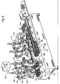
- FIGs. 8-15 An exemplary embodiment of such a modified machine is shown in FIGs. 8-15.
- FiGs. 8 and 9 flat package blanks 400, which have not yet been erected, are discharged from the magazine 405 while at the same time the package blanks 400 are erected in a tubular form, which in the present case has a square cross-section.
- the feeder device 410 which, in the present embodiment, comprises of a rotatable chain provided with carriers 415, the erected package blanks 400 are pushed onto a mandrel 420 provided on the mandrel wheel 425, the mandrel having been moved in position opposite the feeder device. (in the drawing this position is designated I).
- the mandrel wheel 425 is indexed in a counterclockwise direction until it reaches position II, whereupon the mandrel wheel stops again.
- the upper end 32 of the package blank 400 mounted on mandrel 420 is centrally opposite a folding device 430 controlled by an actuator 435, preferably a pneumatic cylinder.
- an actuator 435 preferably a pneumatic cylinder.
- the folding device 43 is moved towards the upper end sections 32 of the package blank 400, the upper end section projecting from mandrel 420, whereby flaps 437 of the folding device 430 are folded inward towards the upper end section of the package blank 400 with a view to initially folding or "breaking" the crease lines previously provided in the upper end section of package blank 400.
- the folding process is, however, interrupted before the wall section of the package blank, which forms the top, has been completely folded inward to its final position, and owing to the elasticity of the material, sections 32 of package blank 400 which projects from mandrel 420 returns substantially to the position in which it was prior to the folding operation.
- the mandrel wheel 425 is again indexed and stops in position III, in which position the pre-folded upper end sections 32 of package blank 400 are centrally opposite a heating device 440.
- hot gas preferably air
- the panels of the upper end section, which are intended to act as sealing sections are heated to such an extent that the thermoplastic material disposed about the paperboard substrate softens.
- a fitment or a complete cap assembly 10 including the fitment is conveyed through a tube 445 from a supply 450.
- the tube 445 is moved proximate the mandrel 420 and guides the fitment between the open panels at upper end 32.
- the fitment engages the mandrel 420 and is held fast thereto by, for example, a vacuum device or the like.
- the tube 445 is then moved from proximate the mandrel 420 to allow the mandrel with the corresponding fitment secured thereto to again be indexed and move to position IV.
- the heated thermoplastic layer is caused to stiffen once the heated faces have been combined by surface fusion, whereby the sections forming the top are held together in the compressed position so as to form a liquid-proof top.
- pressures up to several tons, since pressures of this magnitude cause effective flow of the plastic in the sealing zone and closure of any leakage channels which may occur when overlapping layers of material are joined.
- the container 400 is pulled from mandrel 420 by means of a pull-off device 470 which is vertically displaceable and has at its front part a suction or gripping device that grips the container 400.
- the pulling-off operation is effected by raising the pull-off device 470 with the aid of an actuator 475 until its suction or gripping head 480 comes into contact with the top of container 400.
- the pull-off device 470 is thereafter caused to move downward, the container 400 is pulled from mandrel 420 and lowered between the retaining devices which are arranged on an intermittently movable chain conveyor 485, by means of which the containers 400 are pulled from the mandrel wheel 425 and are caused to be transported in a substantially horizontal direction in an inverted state.
- the mandrel wheel 425 is indexed after completion of the pull-off operation to position I, in which a fresh package blank 400 is pushed on mandrel 420 by the feeder device 410.
- each conveyor 485 is associated with two mandrel wheels 425, so that two containers 400 are transmitted to the conveyor 485 during each indexing operation. Since the conveyor is supplied with two containers 400 during each indexing operation, the container must be moved by two package divisions during each indexing operation, and all processing stations for folding the tops of the containers and for filling and closing the containers 400 must be duplicated. However, since the processing stations are situated in lateral juxtaposition, a common drive mechanism can be used for each pair of devices. Alternatively, one or more servomotors may be used to drive the corresponding mechanisms in a timed relationship.
- Each conveyor 485 comprises two parallel endless chains which are provided with retaining devices 490 whereby the retaining devices located centrally opposite one another on the two chains form between them a space 495 which is so designed that an inverted container 400 can be placed within it.
- a container 400 is pulled from mandrel 420 by the pull-off device 470 and moved downward, it is introduced into the space 500 defined by the retaining devices 490.
- the movement of the conveyor is synchronized with that of the mandrel wheel so that the conveyor moves forward by two retaining device divisions during each indexing operation of the mandrel wheel 425 while fresh empty spaces bounded by the retaining elements 490 are always directly below the mandrels 420 in position VI.
- the bottom end sections 30 of the containers 400 are pre-folded by means of a folding device 505 attached to a yoke 510 which can be raised and lowered.
- the folding operation is effected by at least partially folding the bottom end sections 30 in the manner described above.
- the folding has only the purpose of bending or "breaking" the crease line pattern which has been provided on the package blank and which is intended to define the folding pattern necessary for sealing the top of the container, and hence the folding operation is not completed but the folding device 505 is raised to its upper position once the crease line pattern has been bent.
- the folded containers 400 are at station B, i.e., directly below the filling device 515, by means of which a measured quantity of the product is introduced into the containers.
- Filling of the containers 400 is effected in such a way that the containers are raised about the filling tubes 520 by means of a lifting mechanism and gradually lowered as the container is filled.
- the filled containers are moved in stages and synchronously with the indexing mechanism to station C, where the bottom end sections 30 of the container are directly below a heating device 525.
- the bottom heating device 525 consists of a heating device provided with holes, whereby hot air is blown through the holes which are arranged in such a pattern that the heat reaches only those parts of upper end sections 30 which are intended to be sealed against one another.
- the thermoplastic material is quickly heated to the point of plastification whereupon the containers 33 are moved from station C to station D where the bottom end sections are finally folded and sealed to the configuration shown in FIG. 4.
- the retaining devices which surrounded the containers during transportation are separated and the completed packages are removed from the packaging machine and inverted by a package inverting mechanism 530 that inverts the containers 400 to a righted position for subsequent transport and distribution.
- the packaging machine of the instant embodiment is driven with the aid of an electric motor and a corresponding set of drive shafts and cam mechanisms.
- various configurations are suitable for driving and coordinating the machine stations the illustrated embodiment being but one such configuration.
- the top of the package is formed by folding the upper end sections 32 towards each other and about the fitment.
- the sections 32 which form the top and are folded inward are retained in the folded-inward position by heating the thermoplastic lining of the package blank 400 in the region of sections 35 which form the base, until plastification occurs, whereupon the thermoplastic material lining the surfaces of the sections is bonded after folding by surface fusion so as to form a permanent seal.
- FIGs. 10-12 illustrate one manner in which the top end panels 32 of the containers 400 may be heat sealed about the fitment.
- the fitment 114 is introduced at position III and, further, heating of the top end sections 32 likewise takes place here.
- the fitment 114 may be introduced in the manner shown in FIGs.
- a linear actuator 560 is connected to drive the tube 445 between a first position in which the end 565 of tube 445 including a deflector 570 are clear of the mandrel 420 and the top end panels 32 extending from the mandrel 420, and a second position in which the end 565 of tube 445 is disposed proximate a central portion of the mandrel 420 corresponding to the position at which the fitment 114 will be secured to the container 400.
- the fitment 114 is conveyed through tube 445 by air, gravity, or the like, to cover the opening of a central vacuum channel 575 that is connected to a vacuum source (not shown).
- the vacuum channel 575 assists in securing the fitment 114 to the mandrel 420 while the top of the container 400 is folded and heat sealed about the fitment 114.
- Heating of the upper end panels 32 is best illustrated in connection with FIG. 12.
- the containers 400 are presented to a heating system 580 that provides a hot, sterile gas, such as air, through a plurality of apertures 585 disposed at positions selected to direct the hot gas to the portions of the upper end flaps 32 that will be heat sealed to one another.
- the hot gas is provided at a temperature sufficient to plasticize the polymer layers that are to be used to heat seal the container 400 over the dwell time of the indexing period. It is during this dwell time that the fitment 114 is conveyed into position for sealing to the container 400.
- the fitment 114 preferably formed from a polymer material, is advantageously protected from the hot gas by the tube 445 and deflector 570.
- the upper end panels 32 are folded by the folding mechanism 460 before reaching the cooled pressure die 465.
- One embodiment of such a folding mechanism is illustrated in FiGs. 13 - 15. Further details concerning the operation of the folding mechanism can be found in the foregoing '303 patent, which is incorporated by reference.
- the method by which the container is formed may be modified such that the upper sections 32 are folded upon one another and sealed to one another in a first station prior to addition of the fitment. Thereafter, the container may be removed from the mandrel 420 and the fitment introduced through the opposed open bottom end of the sleeve until the fitment 114 engages the interior surface of the container upper end.
- the upper end of the container would be formed at a first station and the fitment 114 would be subsequently introduced at a second station, with the flange 220 being separately sealed to the interior surfaces of the end sections 32.
- other methods of securing the fitment such as gluing it to the container, ultrasonic attachment, or the like, may be employed.
Landscapes
- Engineering & Computer Science (AREA)
- Mechanical Engineering (AREA)
- Cartons (AREA)
- Making Paper Articles (AREA)
- Table Devices Or Equipment (AREA)
- Devices For Use In Laboratory Experiments (AREA)
- Piezo-Electric Or Mechanical Vibrators, Or Delay Or Filter Circuits (AREA)
- Rigid Containers With Two Or More Constituent Elements (AREA)
- Packages (AREA)
- Closing Of Containers (AREA)
Abstract
Description
- The present invention generally relates to an improved container and, more specifically, to a paperboard-based container having an opening fitment, wherein the container includes hermetically sealed upper and lower ends that prevent wicking of liquid products into the paperboard substrate of the container.
- Today, many types of disposable single-use packages or cartons exist for storing liquids, powders or the like. The liquids may include beverages, such as milk and juice. The containers may be formed from blanks or sheets made of a variety of laminate materials having a substrate such as paperboard, strawboard, pasteboard, cardboard and the like. The substrate material is laminated or coated with a thermoplastic or a similar liquid resistant coating to enable the container to retain liquids. The blanks are folded into a variety of container cross-sections, such as tubular, rectangular, square and the like.
- It has been proposed to form rectangular cartons with side walls made from a paperboard-based laminate material wherein the upper end is made exclusively from a thermoplastic material. Such a proposal is made in
U.S. Patent Nos. 5,158.633 and5,498,149 . As disclosed therein, a thermoplastic material may be shaped and sealed to the container side walls by using an injection molding process. The upper end may be formed from a soft plastic strip placed over the end of the side walls and then heated and thermoformed to the side walls. The thermoform process is effected within an end mold such that the resultant plastic end cap conforms in shape to that of the mold. The end cap may be formed with an integral end cap which receives a plug. The end cap may be threaded to receive a screw cap. - The foregoing container having a thermoformed plastic end cap, depending on the circumstances, may be relatively difficult to manufacture and requires substantial tooling which is added to existing packaging machine. The resultant container may also be more expensive than a similarly shaped container which is entirely formed of the paperboard -based laminate material.
- Gable-top containers, either flattened or erect, are also quite popular and are an alternative to the thermoformed-top container discussed above. The flattened and erect gable shaped ends may include separate opening arrangements, such as a screw cap type fitment or the like. Exemplary opening arrangements are disclosed in
USP 5,248,054 ;USP 2,980,304 ; andUSP 2,432,462 . - The conventional gabled-top containers, however, may also experienced limitations that are dependent upon the circumstances. Gable-shaped ends require more material than flat ends, even though gable shaped and flat ended containers provide the same storage volume. In addition, it is often difficult to manufacture a gable shaped container with a spout and cap. When adding the spout to the gable shaped container, it was added to the erected blank prior to forming the gable. Once the spout is added, the ends of the are folded, heated, and pressed together to form the familiar sealed fin of the gabled-top structure. The spout, however, must be located remote from the fin in order to avoid interference by the spout with the manufacturing equipment which heat seals the fin panels. Such remote placement of the cap often locates the cap in an awkward position to one side of the container.
- To address these problems, conventional containers have been proposed with flat upper ends having a spout and cap opening in the center of the top. However, flat ended containers experience other limitations. In flat ended containers, the adjoining edges of the folded end panels produce seams. These seams expose edges of the paperboard substrate material to the liquid product within the container. The product undergoes a wicking or capillary action and is soaked into the paperboard core of the container thereby degrading the seals and compromising the integrity of the package. In addition, conventional flat ended containers are unable to achieve a hermetic seal along the seams produced at the upper end of the container. Thus, while conventional flat ended containers are liquid tight, such containers are not hermetically sealed and, therefore, are unable to maintain a pressurized interior chamber, such as is required to preserve carbonated liquids. In addition, the non-hermetic seams in conventional paperboard-based containers are an unsatisfactory medium for storing liquids which are highly sensitive to oxygen, such as wine, orange juice, or the like.
- The present invention is directed at a paperboard-based container formed from a blank folded along fold lines, the container having side panels with upper and lower end sections, and the upper end sections defining inner and outer opposed pairs with cut-outs, folded towards one another, wherein the cut-outs combine to define an aperture which receives a fitment sealed to the upper end sections around the aperture. According to the invention each of the inner opposed upper end section pairs is divided along fold lines into a middle region and lateral side regions, and folded under the outer pairs with each side region between a respective middle region and a respective outer end section, to form a flat container top.
- A typical container according to the invention includes a rectanguloid sleeve having upper end sections joined at fold lines with side walls. The upper end sections are divided into inner and outer opposed pairs which are folded toward one another in an overlapping manner to form a generally flat end for the container. Each of the inner and outer opposed sections includes a cutout. When the upper end sections are folded in the manner described above to form the flat end, the cutouts define an aperture having edges that include exposed paperboard substrate. Each of the inner pair of opposed end sections are divided along fold lines into a middle region and laterally opposed side regions. The laterally opposed side regions are folded onto the middle region and are sandwiched between the middle region and the outer pair of opposed sections when folded to form the container top. One of the outer pair of opposed upper end sections is longer than the other so that the longer outer end section overlaps exterior to the shorter of the outer pair of opposed upper end sections. An opening fitment is disposed through the aperture and includes a flange at the interior of the container. The flange covers the exposed edges of the aperture. The fitment is preferably a resealable cover, such as a resealable screw-type spout and cap or the like, but may also be in the form of a generally flattened disc.
- The containers of the invention facilitate the creation of an hermetically sealed paperboard-based container which can be manufactured with a reduced amount of packaging material per unit volume when compared to other selected container types. The foregoing container design may also be exploited with a minimum amount of retooling of the manufacturing equipment.
- The invention also provides a method of fabricating a container from a blank in a packaging machine, the blank having fold lines defining side panels with upper and lower end sections, the upper end sections being formed with cut-outs, wherein each of the inner opposed upper end section pairs is divided along fold lines into a middle region and lateral side regions, which method comprises folding the blank around fold lines to form a tubular body and fitting the body around a mandrel with the upper end sections of the side panels projecting beyond the top of the mandrel; and folding end sealing the upper end sections to close the upper end of the container Around an aperture defined by the juxtaposition of the cut-outs, with the lateral side regions of the inner upper sections under the outer pairs and closed upper end conforming to the contour of the mandrel top; installing and sealing a fitment in the aperture; and closing and sealing the lower end sections of the container.
- A packaging machine according to the invention for fabricating a container from a blank of the kind described above, comprises means for folding a said blank around fold lines therein to form a tubular body, and for fitting such body on a mandrel with its said upper end sections projecting beyond the top of the mandrel; a device for folding and sealing the upper end sections of said body to close the upper end thereof with the lateral side regions between a respective middle region and a respective outer end section, and with the closed end conforming to the contour of the mandrel top; and means for installing a fitment in an aperture formed in said body upper end.
- The invention will now be described by way of example and with reference to the accompanying drawings wherein:
- FIGs. 1- 7 illustrate a blank and container formed from the blank in accordance with one embodiment of the present invention.
- FIGs. 8-15 illustrate one embodiment of an apparatus that may be used to form, fill, and seal the container of FIGs. 1-7.
- Fig. 1 generally illustrates a perspective view of a container formed according to the present invention (generally denoted by reference numeral 2). The
container 2, when completed, may include any desire cross-sectional shape, such as a rectangular shape, circular shape, square shape and the like. Preferably, thecontainer 2 is formed in a rectangular shape withside walls 4, atop 6 and abottom 8. Thetop 6 may include ascrew cap assembly 10 or the like that includes an opening fitment and corresponding cap. - Turning to Fig. 2, a flat blank 12 is illustrated which is utilized to form the
container 2 of Fig. 1. The blank 12 is preferably formed from a laminate material that includes a paperboard substrate disposed between two or more liquid resistant layers, such as layers of polyethylene. The blank 12 includes fourpanel sections 14 divided from one another alongfold lines 16. Optionally, aside overlapping section 18 may be provided integrally along one side of onepanel 14 to be used to form theside seam 15 shown in Fig. 3. Theside overlapping section 18 is separated from thepanel 14 byfold line 20. - As shown in Fig. 3, when the container is folded into its rectangular shape, the
side overlapping section 18 is folded inward alongline 20 to lie adjacent to theinner surface 22 of thepanel 14. The overlappingsection 18 includes anedge 24 extending along its length. Aside lip 26 is folded along the length of the overlappingsection 18 in order to sandwich thelip 26 between thesection 18 and theside panel 14 with theside edge 24 isolated from the interior of the container. By folding thelip 26 in this manner, theside edge 24 is not exposed to the liquid product within the container. - Returning to Fig. 2, the
panels 14 includeside wall portions 28 which define thesidewalls 4 of the formedcontainer 2. Thepanels 14 also include upper andlower end sections end sections side wall portions 28 viafold lines lower end sections outer edges edges - The
end sections 30 cooperate, when folded upon one another, to define thebottom 8 of thecontainer 2, while theend sections 32 cooperate, when folded, to form thetop 6. Thelower end sections 30 include an inner pair ofend sections end sections upper end sections 32 include an inner pair ofend sections end sections end sections lower end sections 30 and the inner pair ofend sections upper end sections 32 are divided from their respective side panels by curved fold lines 36. - In order to facilitate proper folding of the
bottom 8 of thecontainer 2, thelower end sections fold lines middle regions ear regions outer end section 58 includes anoutermost flap 62 which, as will be shown in connection with FIG. 4, overlaps the seal formed by thesections 30 across thebottom 8 of the container. Theend sections outer lips flap 62. - During formation of the
lower end section 30, the inner pair ofopposed end sections lips bottom 8. Thereafter, the outer pair ofend sections lips lower end sections 30 fold inward upon one another in the foregoing manner, theear regions lines middle regions ear regions middle regions outer end sections - Fig. 4 illustrates the final folding of the
lower end sections 30 in the proper relationships. As illustrated, theouter end sections seam 59. Thelip 61 is folded outward alongline 63 away from the interior of the container to isolate theedge 38 from the content of the container. If the curved fold lines illustrated in thelower end 30 of FIG. 4 are employed, theseam 59 resides in a recess thereby providing a generally flattened and stable seating surface for the container. Further details concerning the use of such curved fold lines are described inU.S. Patent No. 5,474,232, issued December 12, 1995 , and entitled "Gable Top Carton and Carton Blank Having Curved Side Creases", which is hereby incorporated by reference. - Returning to Fig. 2, the
upper end sections 32 include an inner pair ofend sections end sections end sections middle regions ear regions ear regions body regions fold lines end sections 30 may include an overlap strip, such asstrip 100 uponend section 84. The end sections 80-86 further includearcuate cutouts - Folding of the
top 6 of thecontainer 2 is illustrated in Fig. 5. As shown, the top is formed by foldingend sections outer tips 81 and 83 (Fig. 4) substantially adjoin one another. Thereafter,end sections overlap 100 overlaps theedge 40 ofsection 86. During this folding operation, theear regions body regions fold lines ear regions middle regions adjacent end sections upper end sections 32 in this manner substantially isolates many edges of the paperboard substrate that would otherwise be exposed to the product content of the container. All edges, including theedge 40, are isolated from the interior of the container. Only theedges - As shown in Fig. 6, the
cap assembly 10 is inserted through theaperture 112 defined by the cutouts outward from the interior of the container through theopening 112 formed when the arcuate cutouts 102-108 join one another. Thecap assembly 10 includes afitment 114 with acircular base flange 116 andtubular stem 117 projecting outward through theopening 112. Theflange 116 includes anupper sealing face 119 which is securely sealed against theinterior surfaces 121 of theupper end sections opening 112. Thefitment 114 seals and isolates theedges cutouts stem 117 may include.threads 122 which receive a corresponding threadedcap 124. - As shown in Fig. 7, the
base flange 116 covers a center region of theend sections edges body regions middle regions end sections end sections 30. - The foregoing container can be manufactured with a minimal degree of modification to traditional gable-top packaging machines. Such machines include the TR/6™, TR/7™, TR/8™, and Tetra Mini™ packaging machines available from Tetra Pak, Inc.
- One example of a traditional packaging machine that can be modified to manufacture the foregoing container is shown and described in
U.S. Patent 3,820,303 . An exemplary embodiment of such a modified machine is shown in FIGs. 8-15. As shown in FiGs. 8 and 9,flat package blanks 400, which have not yet been erected, are discharged from themagazine 405 while at the same time thepackage blanks 400 are erected in a tubular form, which in the present case has a square cross-section. By means of thefeeder device 410, which, in the present embodiment, comprises of a rotatable chain provided withcarriers 415, the erectedpackage blanks 400 are pushed onto amandrel 420 provided on themandrel wheel 425, the mandrel having been moved in position opposite the feeder device. (in the drawing this position is designated I). Once the blank 400 has been pushed ontomandrel 420, themandrel wheel 425 is indexed in a counterclockwise direction until it reaches position II, whereupon the mandrel wheel stops again. - In position II, the
upper end 32 of the package blank 400 mounted onmandrel 420 is centrally opposite afolding device 430 controlled by anactuator 435, preferably a pneumatic cylinder. With the aid of theactuator 430, thefolding device 43 is moved towards theupper end sections 32 of the package blank 400, the upper end section projecting frommandrel 420, whereby flaps 437 of thefolding device 430 are folded inward towards the upper end section of the package blank 400 with a view to initially folding or "breaking" the crease lines previously provided in the upper end section of package blank 400. The folding process is, however, interrupted before the wall section of the package blank, which forms the top, has been completely folded inward to its final position, and owing to the elasticity of the material,sections 32 of package blank 400 which projects frommandrel 420 returns substantially to the position in which it was prior to the folding operation. - When the pre-folding operation is completed, the
mandrel wheel 425 is again indexed and stops in position III, in which position the pre-foldedupper end sections 32 of package blank 400 are centrally opposite aheating device 440. Through theheating device 440 hot gas, preferably air, is blown against the raisedend sections 32 of package blank 400, whereby the panels of the upper end section, which are intended to act as sealing sections are heated to such an extent that the thermoplastic material disposed about the paperboard substrate softens. Additionally, a fitment or acomplete cap assembly 10 including the fitment is conveyed through atube 445 from asupply 450. Thetube 445 is moved proximate themandrel 420 and guides the fitment between the open panels atupper end 32. The fitment engages themandrel 420 and is held fast thereto by, for example, a vacuum device or the like. Thetube 445 is then moved from proximate themandrel 420 to allow the mandrel with the corresponding fitment secured thereto to again be indexed and move to position IV. - While the
mandrel wheel 425 withmandrel 420 moves from position III to position IV,section 32 of package blank 400 projecting frommandrel 420 comes into contact with afolder 460 which folds theupper end sections 32 in the manner described in connection with FIG. 5. At this time, the panels of theupper end sections 32 begin to be heat sealed to one another and to theflange 116 of thefitment 114. When themandrel 420 has reached position IV, a cooled pressure die 465, which can be displaced by anactuator 470, preferably a pneumatic cylinder, is pressed against the folded and sealed top section, whereby a generally flat container top having a fitment is formed. By cooling the heated parts of theend sections 32 at the same time as the sections are pressed together by thepressure plate 465 and the end ofmandrel 420, the heated thermoplastic layer is caused to stiffen once the heated faces have been combined by surface fusion, whereby the sections forming the top are held together in the compressed position so as to form a liquid-proof top. In order to ensure a good seal it is important for the folded top sections to be pressed against one another with great force, and it is advisable to make use of pressures up to several tons, since pressures of this magnitude cause effective flow of the plastic in the sealing zone and closure of any leakage channels which may occur when overlapping layers of material are joined. - Once the base has been pressed on the mandrel wheel is indexed to position V, for which position no operation is provided, so that the
container 400 which has been given a formed and sealed top is turned, after a period of time corresponding to one indexing period, to position VI, in which themandrel 420 is directed downward. - In position VI, the
container 400 is pulled frommandrel 420 by means of a pull-offdevice 470 which is vertically displaceable and has at its front part a suction or gripping device that grips thecontainer 400. The pulling-off operation is effected by raising the pull-offdevice 470 with the aid of anactuator 475 until its suction orgripping head 480 comes into contact with the top ofcontainer 400. When the pull-offdevice 470 is thereafter caused to move downward, thecontainer 400 is pulled frommandrel 420 and lowered between the retaining devices which are arranged on an intermittentlymovable chain conveyor 485, by means of which thecontainers 400 are pulled from themandrel wheel 425 and are caused to be transported in a substantially horizontal direction in an inverted state. Themandrel wheel 425 is indexed after completion of the pull-off operation to position I, in which a fresh package blank 400 is pushed onmandrel 420 by thefeeder device 410. - In the above description, a method of operation has been reported in which a
mandrel wheel 425 carries out a complete indexing cycle, but during each indexing pause operations such operations are concurrently carried out in all positions with the exception of position V. This means that a completely processedcontainer 400 is pulled off during each indexing pause while at the same time a fresh package blank 400 is mounted onmandrel 420. Accordingly, in the present embodiment, the time between two consecutive indexing operations is selected so that all operations in the various positions can be completed. - In the illustrated embodiment, since two or
more mandrel wheels 425 are simultaneously associated with aconveyor 485, two orseveral containers 400 provided with a sealed and formed top are at all times transmitted from themandrel wheel 425 to theconveyor 485 by means of two or more pull-offdevices 470. With the machine here described eachconveyor 485 is associated with twomandrel wheels 425, so that twocontainers 400 are transmitted to theconveyor 485 during each indexing operation. Since the conveyor is supplied with twocontainers 400 during each indexing operation, the container must be moved by two package divisions during each indexing operation, and all processing stations for folding the tops of the containers and for filling and closing thecontainers 400 must be duplicated. However, since the processing stations are situated in lateral juxtaposition, a common drive mechanism can be used for each pair of devices. Alternatively, one or more servomotors may be used to drive the corresponding mechanisms in a timed relationship. - Each
conveyor 485 comprises two parallel endless chains which are provided with retainingdevices 490 whereby the retaining devices located centrally opposite one another on the two chains form between them aspace 495 which is so designed that aninverted container 400 can be placed within it. When acontainer 400 is pulled frommandrel 420 by the pull-offdevice 470 and moved downward, it is introduced into thespace 500 defined by the retainingdevices 490. For this to be possible, the movement of the conveyor is synchronized with that of the mandrel wheel so that the conveyor moves forward by two retaining device divisions during each indexing operation of themandrel wheel 425 while fresh empty spaces bounded by the retainingelements 490 are always directly below themandrels 420 in position VI. - At station A the
bottom end sections 30 of thecontainers 400 are pre-folded by means of afolding device 505 attached to ayoke 510 which can be raised and lowered. The folding operation is effected by at least partially folding thebottom end sections 30 in the manner described above. The folding has only the purpose of bending or "breaking" the crease line pattern which has been provided on the package blank and which is intended to define the folding pattern necessary for sealing the top of the container, and hence the folding operation is not completed but thefolding device 505 is raised to its upper position once the crease line pattern has been bent. - After indexing of the
mandrel wheel 425 and displacement of theconveyor 485 by one stage, the foldedcontainers 400 are at station B, i.e., directly below the fillingdevice 515, by means of which a measured quantity of the product is introduced into the containers. Filling of thecontainers 400 is effected in such a way that the containers are raised about the fillingtubes 520 by means of a lifting mechanism and gradually lowered as the container is filled. Thereafter the filled containers are moved in stages and synchronously with the indexing mechanism to station C, where thebottom end sections 30 of the container are directly below aheating device 525. Just like thetop heating device 440, thebottom heating device 525 consists of a heating device provided with holes, whereby hot air is blown through the holes which are arranged in such a pattern that the heat reaches only those parts ofupper end sections 30 which are intended to be sealed against one another. The thermoplastic material is quickly heated to the point of plastification whereupon the containers 33 are moved from station C to station D where the bottom end sections are finally folded and sealed to the configuration shown in FIG. 4. At station E at the end of the conveyor, the retaining devices which surrounded the containers during transportation are separated and the completed packages are removed from the packaging machine and inverted by apackage inverting mechanism 530 that inverts thecontainers 400 to a righted position for subsequent transport and distribution. - Although the drive and coordination of the various mechanisms at the processing stations can be accomplished through the use of one or more servomotors and an appropriate control system, the packaging machine of the instant embodiment is driven with the aid of an electric motor and a corresponding set of drive shafts and cam mechanisms. However, it will be readily recognized that various configurations are suitable for driving and coordinating the machine stations the illustrated embodiment being but one such configuration.
- With packaging machines of the type previously described, the top of the package is formed by folding the
upper end sections 32 towards each other and about the fitment. Thesections 32 which form the top and are folded inward are retained in the folded-inward position by heating the thermoplastic lining of the package blank 400 in the region of sections 35 which form the base, until plastification occurs, whereupon the thermoplastic material lining the surfaces of the sections is bonded after folding by surface fusion so as to form a permanent seal. - FIGs. 10-12 illustrate one manner in which the
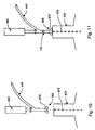
top end panels 32 of thecontainers 400 may be heat sealed about the fitment. In the embodiment illustrated, thefitment 114 is introduced at position III and, further, heating of thetop end sections 32 likewise takes place here. Thefitment 114 may be introduced in the manner shown in FIGs. 10 and 11 whereby alinear actuator 560 is connected to drive thetube 445 between a first position in which theend 565 oftube 445 including adeflector 570 are clear of themandrel 420 and thetop end panels 32 extending from themandrel 420, and a second position in which theend 565 oftube 445 is disposed proximate a central portion of themandrel 420 corresponding to the position at which thefitment 114 will be secured to thecontainer 400. When disposed in the second position, illustrated in FIG. 11, thefitment 114 is conveyed throughtube 445 by air, gravity, or the like, to cover the opening of acentral vacuum channel 575 that is connected to a vacuum source (not shown). Thevacuum channel 575 assists in securing thefitment 114 to themandrel 420 while the top of thecontainer 400 is folded and heat sealed about thefitment 114. - Heating of the
upper end panels 32 is best illustrated in connection with FIG. 12. As shown, thecontainers 400 are presented to aheating system 580 that provides a hot, sterile gas, such as air, through a plurality ofapertures 585 disposed at positions selected to direct the hot gas to the portions of the upper end flaps 32 that will be heat sealed to one another. The hot gas is provided at a temperature sufficient to plasticize the polymer layers that are to be used to heat seal thecontainer 400 over the dwell time of the indexing period. It is during this dwell time that thefitment 114 is conveyed into position for sealing to thecontainer 400. Thefitment 114, preferably formed from a polymer material, is advantageously protected from the hot gas by thetube 445 anddeflector 570. - As the
containers 400 are indexed from position III to position IV, theupper end panels 32 are folded by thefolding mechanism 460 before reaching the cooled pressure die 465. One embodiment of such a folding mechanism is illustrated in FiGs. 13 - 15. Further details concerning the operation of the folding mechanism can be found in the foregoing '303 patent, which is incorporated by reference. - As a further alternative, the method by which the container is formed may be modified such that the
upper sections 32 are folded upon one another and sealed to one another in a first station prior to addition of the fitment. Thereafter, the container may be removed from themandrel 420 and the fitment introduced through the opposed open bottom end of the sleeve until thefitment 114 engages the interior surface of the container upper end. Thus, the upper end of the container would be formed at a first station and thefitment 114 would be subsequently introduced at a second station, with the flange 220 being separately sealed to the interior surfaces of theend sections 32. Alternatively, other methods of securing the fitment, such as gluing it to the container, ultrasonic attachment, or the like, may be employed.
Claims (13)
- A paperboard-based container (2) formed from a blank (400) folded along fold lines, the container having side panels (4) with upper and lower end sections, and the upper end sections (80,82,84,86) defining inner and outer opposed pairs with cut-outs (103,105,107,109), folded towards one another, wherein the cut-outs combine to define an aperture (112) which receives a fitment (10) sealed to the upper end sections around the aperture,
CHARACTERIZED IN THAT
each of the inner opposed upper end section pairs (102,104) is divided along fold lines (96,98) into a middle region (88,90) and lateral side regions (92,94), and folded under the outer pairs (106,108) with each side region between a respective middle region and a respective outer end section, to form a flat container top. - A container according to Claim 1 wherein the cut-outs (103,105,107,109) are arcuate and combine to define a substantially circular aperture (112).
- A container according to Claim 1 or Claim 2 wherein the lower end sections (42,44,58,60) are folded to form a bottom in which all exposed edges of the paperboard blank are isolated from the interior of the container.
- A container according to Claim 3 wherein the lower end sections form inner (42,44) and outer (58,60) opposed pairs with each inner section being divided along fold lines (46,48) into a middle region (50,52) and lateral side regions (54,56), and folded under the outer sections (58,60) with each side region (54,56) between a respective middle region (50,52) and a respective outer section.
- A container according to Claim 4 wherein the side panels (4) with which the outer end sections (58,60) are aligned are extended relative to those with which the inner end sections (42,44) are aligned, to form a recess into which the outer end sections are folded.
- A container according to any preceding Claim including a fitment (10) in the aperture (112) and comprising a flange (116) with an upper face (119) sealed against interior surfaces (121) of the upper end sections (80,82,84,86).
- A method of fabricating a container (2) from a blank (400) in a packaging machine, the blank having fold lines defining side panels (4) with upper and lower end sections, the upper end sections (80,82,84,86) being formed with cut-outs (103,105,107,109), wherein each of the inner opposed upper end section pairs (102,104) is divided along fold lines (96,98) into a middle region (88,90) and lateral side regions (92,94), which method comprises folding the blank (400) around fold lines to form a tubular body and fitting the body around a mandrel (420) with the upper end sections (80,82,84,86) of the side panels projecting beyond the top of the mandrel (420); and folding end sealing the upper end sections to close the upper end of the container (2) around an aperture (112) defined by the juxtaposition of the cut-outs (103,105,107,109), with the lateral side regions (92,94) of the inner upper sections (102,104) under the outer pairs (106,108) and closed upper end conforming to the contour of the mandrel top; installing and sealing a fitment (10) in the aperture (12); and closing and sealing the lower end sections (42,44,58,60) of the container.
- A method according to Claim 7 wherein the fitment (10) is installed in the aperture (112) in the end sections after removal of the partially formed container for the mandrel (420) and prior to closure and sealing of the lower end sections.
- A method according to Claim 7 wherein the fitment (10) is installed in the aperture prior to removal of the partially formed container from the mandrel (420).
- A packaging machine for fabricating a container (2) afrom a blank (400) having fold lines defining side panels (14) with upper and lower sections, the upper sections (80,82,84,86) defining inner and outer opposed pairs with cut-outs (103,105,107,109), and wherein each of the inner opposed upper end section pairs (102,104) is divided along fold lines (96,98) into a middle region (88,90) and lateral side regions (92,94), which machine comprises means for folding a said blank around fold lines therein to form a tubular body, and for fitting such body on a mandrel (420) with its said upper end sections (80,82,84,86) projecting beyond the top of the mandrel (420); a device (430) for folding and sealing the upper end sections of said body to close the upper end thereof with the lateral side regions (92,94) between a respective middle region and a respective outer end section, and with the closed end conforming to the contour of the mandrel top; and means for installing a fitment (10) in an aperture formed in said body upper end.
- A machine according to Claim 10 wherein the fitment installing means is operative when the body is mounted on the mandrel (420).
- A machine according to Claim 10 including vacuum means for holding a fitment (10) on the top end of the mandrel (420) during operation of the folding device.
- A machine according to Claim 11 or Claim 12 wherein the folding and sealing device includes a pressure plate (465) for sealing the upper end sections of the tubular body, which pressure plate has a recess for receiving the fitment (10) during operation of the device.
Priority Applications (1)
| Application Number | Priority Date | Filing Date | Title |
|---|---|---|---|
| DE69738295T DE69738295T3 (en) | 1996-04-25 | 1997-04-08 | OPENING ARRANGEMENT ON A CONTAINER WITH A FLAT UPPER WALL |
Applications Claiming Priority (3)
| Application Number | Priority Date | Filing Date | Title |
|---|---|---|---|
| US639162 | 1996-04-25 | ||
| US08/639,162 US5704541A (en) | 1996-04-25 | 1996-04-25 | Flat-top container with an opening fitment |
| PCT/US1997/005712 WO1997039958A1 (en) | 1996-04-25 | 1997-04-08 | Flat-top container with an opening fitment |
Publications (4)
| Publication Number | Publication Date |
|---|---|
| EP0907576A1 EP0907576A1 (en) | 1999-04-14 |
| EP0907576A4 EP0907576A4 (en) | 2002-10-16 |
| EP0907576B1 true EP0907576B1 (en) | 2007-11-14 |
| EP0907576B2 EP0907576B2 (en) | 2013-07-10 |
Family
ID=24562984
Family Applications (1)
| Application Number | Title | Priority Date | Filing Date |
|---|---|---|---|
| EP97920177.9A Expired - Lifetime EP0907576B2 (en) | 1996-04-25 | 1997-04-08 | Flat-top container with an opening fitment |
Country Status (10)
| Country | Link |
|---|---|
| US (1) | US5704541A (en) |
| EP (1) | EP0907576B2 (en) |
| JP (1) | JP3934680B2 (en) |
| AT (1) | ATE378266T1 (en) |
| AU (1) | AU719745B2 (en) |
| BR (1) | BR9709743A (en) |
| CA (1) | CA2251894C (en) |
| DE (1) | DE69738295T3 (en) |
| NO (1) | NO323872B1 (en) |
| WO (1) | WO1997039958A1 (en) |
Families Citing this family (48)
| Publication number | Priority date | Publication date | Assignee | Title |
|---|---|---|---|---|
| US5738272A (en) * | 1996-03-21 | 1998-04-14 | Tetra Laval Holdings & Finance S.A. | Gable top carton and carton blank having reduced surface area per unit volume |
| US6016953A (en) * | 1997-08-14 | 2000-01-25 | Tetra Laval Holdings & Finance, Sa | Tetrahedral top carton |
| USD420907S (en) * | 1998-09-02 | 2000-02-22 | Tetra Laval Holdings & Finance, Sa | Beveled edge carton |
| US6551639B1 (en) | 2000-02-01 | 2003-04-22 | Rebecca R. Nye | Container for storage and serving of breastmilk |
| PT1172301E (en) | 2000-07-11 | 2005-02-28 | Tetra Laval Holdings & Finance | SEALED PACKAGING FOR FOOD PRODUCTS FLUIDS AND CORRESPONDING PRODUCTION METHOD |
| USD480965S1 (en) | 2001-06-05 | 2003-10-21 | Tetra Laval Holdings & Finance S.A. | Packaging |
| USD494861S1 (en) | 2001-11-30 | 2004-08-24 | Tetra Laval Holdings & Finance Sa | Packaging container |
| USD491801S1 (en) | 2002-05-17 | 2004-06-22 | Tetra Laval Holdings & Finance Sa | Multipack |
| USD501397S1 (en) | 2002-05-24 | 2005-02-01 | Tetra Laval Holdings & Finance S.A. | Package for liquids |
| USD489974S1 (en) | 2002-07-03 | 2004-05-18 | Tetra Laval Holdings & Finance S.A. | Packaging |
| ITBO20020484A1 (en) * | 2002-07-25 | 2004-01-26 | Azionaria Costruzioni Acma Spa | PLANT AND METHOD FOR THE CREATION OF CONTAINERS, IN PARTICULAR FOR THE CONSERVATION OF FOOD SUBSTANCES |
| SE0203306D0 (en) * | 2002-11-08 | 2002-11-08 | Tetra Laval Holdings & Finance | Packaging and method of making a package |
| US20040180770A1 (en) * | 2003-03-11 | 2004-09-16 | Cook Matthew R. | Machine for and method of securing a lining bag at precise locations on the inner surface of a container blank |
| USD537726S1 (en) | 2003-05-09 | 2007-03-06 | Tetra Laval Holdings & Finance S.A. | Packaging |
| USD518716S1 (en) | 2003-07-11 | 2006-04-11 | Tetra Laval Holdings & Finance S.A. | Bottle cap |
| USD532687S1 (en) | 2003-12-09 | 2006-11-28 | Tetra Laval Holdings & Finance S.A. | Container |
| USD538154S1 (en) | 2003-12-09 | 2007-03-13 | Tetra Laval Holdings & Finance S.A. | Container |
| US7313895B2 (en) * | 2004-07-20 | 2008-01-01 | Tetra Laval Holdings & Finance, Sa | Molding unit for forming direct injection molded closures |
| US7571846B2 (en) * | 2004-07-20 | 2009-08-11 | Tetra Laval Holdings & Finance, S.A. | Carton blank for direct injection molded closures |
| SE528872C2 (en) * | 2005-07-08 | 2007-03-06 | Tetra Laval Holdings & Finance | Cross-sealing device and method |
| DE102005048821A1 (en) * | 2005-10-10 | 2007-04-12 | Georg Menshen Gmbh & Co. Kg | Packaging container for liquids or bulk material has a top stub-shaped container area to seal the container as a peripheral shoulder tapering upwards and supporting an emptying connection piece |
| GB0524789D0 (en) | 2005-12-05 | 2006-01-11 | Myerscough Martin | Container |
| SE529720C2 (en) * | 2006-03-10 | 2007-11-06 | Tetra Laval Holdings & Finance | Method of manufacturing a package |
| US8231024B2 (en) | 2007-08-08 | 2012-07-31 | Clear Lam Packaging, Inc. | Flexible, stackable container and method and system for manufacturing same |
| US8066137B2 (en) | 2007-08-08 | 2011-11-29 | Clear Lam Packaging, Inc. | Flexible, stackable container including a lid and package body folded from a single sheet of film |
| US8602242B2 (en) * | 2008-11-06 | 2013-12-10 | Clear Lam Packaging, Inc. | Flexible, stackable container used for storing a quantity of product and method for manufacturing same |
| US9022913B2 (en) * | 2009-11-02 | 2015-05-05 | Rock-Tenn Shared Services, Llc | Methods and a machine for forming a container from a blank |
| WO2014018370A1 (en) * | 2012-07-25 | 2014-01-30 | Greater Good, Inc. | Fluid container |
| CA2825226C (en) | 2012-08-22 | 2016-11-29 | Meadwestvaco Corporation | Paper-based container lids and methods for making the same |
| CN109018686B (en) | 2012-10-26 | 2020-11-17 | 优装有限责任公司 | Flexible container and method of making same |
| US10207850B2 (en) | 2012-10-26 | 2019-02-19 | Primapak, Llc. | Flexible package and method of making same |
| WO2014193608A1 (en) | 2013-05-29 | 2014-12-04 | Greater Good, Inc. | Compostable container with elongate connector |
| CN105745155B (en) * | 2013-11-26 | 2019-11-08 | 卡夫食品研究和开发股份有限公司 | Packages and package blanks |
| US20150230642A1 (en) * | 2014-02-18 | 2015-08-20 | Otb Packaging, Llc | Soup box container |
| DE102014006099B4 (en) * | 2014-04-29 | 2017-11-30 | Sig Technology Ag | Method and device for thermally activating packaging sheaths |
| US10994882B2 (en) | 2014-05-19 | 2021-05-04 | Primapak, Llc | Apparatus and method for making a flexible package |
| KR20170125822A (en) | 2015-02-27 | 2017-11-15 | 엘비피 매뉴팩츄어링 엘엘씨 | Beverage container |
| USD785448S1 (en) | 2015-02-27 | 2017-05-02 | Lbp Manufacturing Llc | Beverage container |
| USD772054S1 (en) | 2015-03-30 | 2016-11-22 | Lbp Manufacturing Llc | Beverage container |
| DE102015110526B4 (en) | 2015-06-30 | 2018-08-23 | Sig Technology Ag | Pouring element for a packaging and composite packaging with such a pouring element |
| CN107810148B (en) | 2015-06-30 | 2019-04-09 | Sig技术股份公司 | Pouring element for packaging and composite packaging having such pouring element |
| EP3112283B1 (en) | 2015-06-30 | 2018-01-31 | SIG Technology AG | Pouring element for an item of packaging and composite packaging comprising such a pouring element |
| JP6660120B2 (en) * | 2015-08-25 | 2020-03-04 | 日本製紙株式会社 | Container made of paper containing liquid contents for refilling |
| WO2017048676A1 (en) | 2015-09-18 | 2017-03-23 | Clear Lam Packaging, Inc. | Apparatus and method for making a flexible package |
| DE102017114614A1 (en) * | 2017-06-30 | 2019-01-03 | Sig Technology Ag | Device for producing packaging with an independent mandrel wheel drive |
| US11548727B2 (en) * | 2018-07-17 | 2023-01-10 | Christopher E. Boyea | Transformative extender and method thereof |
| USD1063605S1 (en) * | 2022-04-14 | 2025-02-25 | Cj Cheiljedang Corporation | Packaging container for foodstuff |
| JP1764475S (en) * | 2022-10-11 | 2024-02-28 | food packaging containers |
Family Cites Families (35)
| Publication number | Priority date | Publication date | Assignee | Title |
|---|---|---|---|---|
| US2147349A (en) * | 1934-11-14 | 1939-02-14 | Piquerez Emile | Packing or wrapping for viscous liquids and pasty materials |
| US2432462A (en) * | 1942-04-09 | 1947-12-09 | Harry F Waters | Dispensing tube |
| US2454919A (en) † | 1943-01-19 | 1948-11-30 | Lord Baltimore Press | Multiply container with dispensing outlet secured thereto |
| US2980304A (en) * | 1958-02-15 | 1961-04-18 | Sisco Richard | Paperboard fluid container |
| US3119543A (en) * | 1961-08-28 | 1964-01-28 | James H Walker | Neck securement for containers |
| US3337033A (en) * | 1965-03-22 | 1967-08-22 | Riegel Paper Corp | Carton |
| US3820303A (en) * | 1971-03-25 | 1974-06-28 | Tetra Pak Int | Packaging machine |
| SE361857B (en) † | 1971-03-25 | 1973-11-19 | Tetra Pak Int | |
| US3756471A (en) * | 1971-08-19 | 1973-09-04 | Eastman Kodak Co | Dispenser container having a tear-out sight gauge |
| US4174051A (en) * | 1978-07-26 | 1979-11-13 | The Continental Group, Inc. | Protective locking flaps for opening in sealed corrugated containers |
| US4246062A (en) * | 1979-03-26 | 1981-01-20 | Christine William C | Apparatus for attaching a fitment to a pouch |
| DE3043134C2 (en) * | 1980-11-15 | 1986-06-19 | Altstädter Verpackungsvertriebs Gesellschaft mbH, 6102 Pfungstadt | Packing for flowable products |
| GB2170479B (en) | 1985-02-05 | 1988-09-28 | Tetra Pak Int | A pack for liquids |
| US4726468A (en) * | 1985-03-11 | 1988-02-23 | Chicago Corrugated Box Co. | Stabilizer box with variable opening |
| DE3526602A1 (en) * | 1985-07-25 | 1987-01-29 | Bosch Gmbh Robert | METHOD FOR PRODUCING A PACKAGING CONTAINER WITH A RBERPRESSURE VALVE |
| US4788811A (en) * | 1986-05-17 | 1988-12-06 | Dai Nippon Insatsu Kabushiki Kaisha | Process and apparatus for assembling and liquor-charging of packages of paper and the like |
| DE3836069C1 (en) † | 1988-10-22 | 1989-12-07 | Henkel Kgaa, 4000 Duesseldorf, De | |
| DE3942319A1 (en) * | 1989-12-21 | 1991-06-27 | Pkl Verpackungssysteme Gmbh | CONTAINER FOR LIQUIDS AND BUBBLE GOODS IN THE FORM OF AN ESSENTIAL SQUARE CARDBOARD CARTON, ESPECIALLY CARDBOARD PLASTIC MULTILAYER COMPOSITE MATERIAL |
| US5058360A (en) * | 1990-04-04 | 1991-10-22 | Toppan Printing Co., Ltd. | Filling and sealing apparatus for fluid containing package |
| US5110041A (en) * | 1990-08-24 | 1992-05-05 | International Paper Company | In-line fitment sealing apparatus and method |
| US5219320A (en) * | 1991-02-20 | 1993-06-15 | Capitol Spouts, Inc. | Method of and apparatus for attaching a spout to a planar portion of a container |
| ES2068626T3 (en) * | 1991-03-19 | 1995-04-16 | Toppan Printing Co Ltd | LIQUID CONTAINER. |
| JP2743702B2 (en) * | 1991-08-06 | 1998-04-22 | 凸版印刷株式会社 | Liquid storage container manufacturing equipment |
| DE9109759U1 (en) † | 1991-08-07 | 1991-11-21 | Europa Carton Ag, 2000 Hamburg | Liquid pack |
| SE468893B (en) * | 1991-09-04 | 1993-04-05 | Tetra Alfa Holdings | OPENING DEVICE FOR PACKAGING CONTAINERS |
| US5484374A (en) * | 1991-10-25 | 1996-01-16 | Nimco Corporation | Method and apparatus for attaching a spout to a container |
| US5203470A (en) * | 1992-05-05 | 1993-04-20 | The Procter & Gamble Company | Separable bag-in-box composite container |
| JPH07501997A (en) * | 1992-09-30 | 1995-03-02 | テトラ レックス パッケイジング システムズ インコーポレイティド | Injection member installation method and device |
| US5366433A (en) * | 1993-06-24 | 1994-11-22 | Mccormick Charles M | Safety clutch and its use in capping milk cartons |
| US5435803A (en) * | 1993-07-01 | 1995-07-25 | Elopak Systems A.G. | Container fitment applicator |
| SE501660C2 (en) | 1993-08-31 | 1995-04-10 | Tetra Laval Holdings & Finance | Device for thermoforming pouring pipes |
| US5473857A (en) * | 1993-11-16 | 1995-12-12 | International Paper Company | System integration for hot melt sealing of fitments in-line with form/fill/seal machine |
| US5474232A (en) | 1994-05-06 | 1995-12-12 | Ljungstroem; Tommy B. G. | Gable top carton and carton blank with curved side creases |
| US5943840A (en) * | 1996-04-25 | 1999-08-31 | Tetra Laval Holdings & Finance, Sa | Method and apparatus for forming the top of a container with a fitment thereon |
| US5964687A (en) * | 1996-07-16 | 1999-10-12 | Elopak Systems Ag | Container fitment applicator |
-
1996
- 1996-04-25 US US08/639,162 patent/US5704541A/en not_active Expired - Lifetime
-
1997
- 1997-04-08 BR BR9709743A patent/BR9709743A/en not_active IP Right Cessation
- 1997-04-08 JP JP53809897A patent/JP3934680B2/en not_active Expired - Lifetime
- 1997-04-08 DE DE69738295T patent/DE69738295T3/en not_active Expired - Lifetime
- 1997-04-08 WO PCT/US1997/005712 patent/WO1997039958A1/en not_active Ceased
- 1997-04-08 EP EP97920177.9A patent/EP0907576B2/en not_active Expired - Lifetime
- 1997-04-08 AU AU24438/97A patent/AU719745B2/en not_active Expired
- 1997-04-08 CA CA002251894A patent/CA2251894C/en not_active Expired - Lifetime
- 1997-04-08 AT AT97920177T patent/ATE378266T1/en not_active IP Right Cessation
-
1998
- 1998-10-21 NO NO19984902A patent/NO323872B1/en not_active IP Right Cessation
Also Published As
| Publication number | Publication date |
|---|---|
| JP2000508994A (en) | 2000-07-18 |
| JP3934680B2 (en) | 2007-06-20 |
| CA2251894A1 (en) | 1997-10-30 |
| EP0907576A4 (en) | 2002-10-16 |
| NO984902L (en) | 1998-12-23 |
| WO1997039958A1 (en) | 1997-10-30 |
| NO323872B1 (en) | 2007-07-16 |
| NO984902D0 (en) | 1998-10-21 |
| CA2251894C (en) | 2005-07-26 |
| US5704541A (en) | 1998-01-06 |
| AU2443897A (en) | 1997-11-12 |
| AU719745B2 (en) | 2000-05-18 |
| BR9709743A (en) | 1999-08-10 |
| EP0907576A1 (en) | 1999-04-14 |
| DE69738295D1 (en) | 2007-12-27 |
| EP0907576B2 (en) | 2013-07-10 |
| DE69738295T3 (en) | 2013-09-26 |
| DE69738295T2 (en) | 2008-03-13 |
| ATE378266T1 (en) | 2007-11-15 |
Similar Documents
| Publication | Publication Date | Title |
|---|---|---|
| EP0907576B1 (en) | Flat-top container with an opening fitment | |
| US5867966A (en) | Method and apparatus for forming the top of a container | |
| US5943840A (en) | Method and apparatus for forming the top of a container with a fitment thereon | |
| US4848063A (en) | Method of manufacturing packaging container | |
| US5110041A (en) | In-line fitment sealing apparatus and method | |
| US5155980A (en) | Forming device in packaging machines | |
| US5829228A (en) | Method and apparatus for forming the top of a container | |
| US3785113A (en) | Packaging machine | |
| US3800677A (en) | Apparatus for forming carton | |
| US4838847A (en) | Packaging machine | |
| US6881180B2 (en) | Apparatus for forming a bottom closure for a container | |
| EP3015371B1 (en) | Packaging and filling device | |
| EP3015372B1 (en) | Packaging and filling device | |
| US5924267A (en) | Process and a device for closing filled folded-carton packages | |
| EP0805748B1 (en) | Carton bottom seal | |
| EP0938965B1 (en) | Heating device for heat-sealing bottom portions of containers | |
| CN117083227A (en) | Composite packaging material sheet, method of forming composite packaging material sheet, composite package, and method of forming composite package | |
| EP1824744A1 (en) | Carton with folded-in gusset tips | |
| RU2172710C2 (en) | Carboard base container (design versions) | |
| WO2007071698A1 (en) | Improvements in or relating to packaging | |
| JP2002510256A (en) | Method and apparatus for forming the top of a carton | |
| SE8005048L (en) | PROCEDURE FOR FORMING A LIQUID CONTAINER AND APPARATUS FOR IMPLEMENTATION OF THE PROCEDURE | |
| WO2006090171A9 (en) | Moulded closure for liquid containing package |
Legal Events
| Date | Code | Title | Description |
|---|---|---|---|
| PUAI | Public reference made under article 153(3) epc to a published international application that has entered the european phase |
Free format text: ORIGINAL CODE: 0009012 |
|
| 17P | Request for examination filed |
Effective date: 19981116 |
|
| AK | Designated contracting states |
Kind code of ref document: A1 Designated state(s): AT BE CH DE DK ES FI FR GB GR IE IT LI LU MC NL PT SE |
|
| A4 | Supplementary search report drawn up and despatched |
Effective date: 20020902 |
|
| AK | Designated contracting states |
Kind code of ref document: A4 Designated state(s): AT BE CH DE DK ES FI FR GB GR IE IT LI LU MC NL PT SE |
|
| RIC1 | Information provided on ipc code assigned before grant |
Free format text: 7B 65D 43/08 A, 7B 65D 5/74 B, 7B 31B 3/28 B, 7B 65D 5/06 B |
|
| GRAP | Despatch of communication of intention to grant a patent |
Free format text: ORIGINAL CODE: EPIDOSNIGR1 |
|
| GRAS | Grant fee paid |
Free format text: ORIGINAL CODE: EPIDOSNIGR3 |
|
| GRAA | (expected) grant |
Free format text: ORIGINAL CODE: 0009210 |
|
| AK | Designated contracting states |
Kind code of ref document: B1 Designated state(s): AT BE CH DE DK ES FI FR GB GR IE IT LI LU MC NL PT SE |
|
| REG | Reference to a national code |
Ref country code: GB Ref legal event code: FG4D |
|
| REG | Reference to a national code |
Ref country code: CH Ref legal event code: EP |
|
| REG | Reference to a national code |
Ref country code: IE Ref legal event code: FG4D |
|
| REF | Corresponds to: |
Ref document number: 69738295 Country of ref document: DE Date of ref document: 20071227 Kind code of ref document: P |
|
| ET | Fr: translation filed | ||
| PG25 | Lapsed in a contracting state [announced via postgrant information from national office to epo] |
Ref country code: SE Free format text: LAPSE BECAUSE OF FAILURE TO SUBMIT A TRANSLATION OF THE DESCRIPTION OR TO PAY THE FEE WITHIN THE PRESCRIBED TIME-LIMIT Effective date: 20080214 Ref country code: NL Free format text: LAPSE BECAUSE OF FAILURE TO SUBMIT A TRANSLATION OF THE DESCRIPTION OR TO PAY THE FEE WITHIN THE PRESCRIBED TIME-LIMIT Effective date: 20071114 Ref country code: LI Free format text: LAPSE BECAUSE OF FAILURE TO SUBMIT A TRANSLATION OF THE DESCRIPTION OR TO PAY THE FEE WITHIN THE PRESCRIBED TIME-LIMIT Effective date: 20071114 Ref country code: ES Free format text: LAPSE BECAUSE OF FAILURE TO SUBMIT A TRANSLATION OF THE DESCRIPTION OR TO PAY THE FEE WITHIN THE PRESCRIBED TIME-LIMIT Effective date: 20080225 Ref country code: CH Free format text: LAPSE BECAUSE OF FAILURE TO SUBMIT A TRANSLATION OF THE DESCRIPTION OR TO PAY THE FEE WITHIN THE PRESCRIBED TIME-LIMIT Effective date: 20071114 |
|
| NLV1 | Nl: lapsed or annulled due to failure to fulfill the requirements of art. 29p and 29m of the patents act | ||
| REG | Reference to a national code |
Ref country code: CH Ref legal event code: PL |
|
| PG25 | Lapsed in a contracting state [announced via postgrant information from national office to epo] |
Ref country code: AT Free format text: LAPSE BECAUSE OF FAILURE TO SUBMIT A TRANSLATION OF THE DESCRIPTION OR TO PAY THE FEE WITHIN THE PRESCRIBED TIME-LIMIT Effective date: 20071114 |
|
| PG25 | Lapsed in a contracting state [announced via postgrant information from national office to epo] |
Ref country code: DK Free format text: LAPSE BECAUSE OF FAILURE TO SUBMIT A TRANSLATION OF THE DESCRIPTION OR TO PAY THE FEE WITHIN THE PRESCRIBED TIME-LIMIT Effective date: 20071114 |
|
| PLBI | Opposition filed |
Free format text: ORIGINAL CODE: 0009260 |
|
| PG25 | Lapsed in a contracting state [announced via postgrant information from national office to epo] |
Ref country code: BE Free format text: LAPSE BECAUSE OF FAILURE TO SUBMIT A TRANSLATION OF THE DESCRIPTION OR TO PAY THE FEE WITHIN THE PRESCRIBED TIME-LIMIT Effective date: 20071114 |
|
| PLAX | Notice of opposition and request to file observation + time limit sent |
Free format text: ORIGINAL CODE: EPIDOSNOBS2 |
|
| 26 | Opposition filed |
Opponent name: SIG TECHNOLOGY AG Effective date: 20080814 |
|
| PG25 | Lapsed in a contracting state [announced via postgrant information from national office to epo] |
Ref country code: PT Free format text: LAPSE BECAUSE OF FAILURE TO SUBMIT A TRANSLATION OF THE DESCRIPTION OR TO PAY THE FEE WITHIN THE PRESCRIBED TIME-LIMIT Effective date: 20080414 |
|
| PG25 | Lapsed in a contracting state [announced via postgrant information from national office to epo] |
Ref country code: MC Free format text: LAPSE BECAUSE OF NON-PAYMENT OF DUE FEES Effective date: 20080430 |
|
| PLAF | Information modified related to communication of a notice of opposition and request to file observations + time limit |
Free format text: ORIGINAL CODE: EPIDOSCOBS2 |
|
| PG25 | Lapsed in a contracting state [announced via postgrant information from national office to epo] |
Ref country code: GR Free format text: LAPSE BECAUSE OF FAILURE TO SUBMIT A TRANSLATION OF THE DESCRIPTION OR TO PAY THE FEE WITHIN THE PRESCRIBED TIME-LIMIT Effective date: 20080215 |
|
| PLBB | Reply of patent proprietor to notice(s) of opposition received |
Free format text: ORIGINAL CODE: EPIDOSNOBS3 |
|
| PG25 | Lapsed in a contracting state [announced via postgrant information from national office to epo] |
Ref country code: IE Free format text: LAPSE BECAUSE OF NON-PAYMENT OF DUE FEES Effective date: 20080408 |
|
| PG25 | Lapsed in a contracting state [announced via postgrant information from national office to epo] |
Ref country code: FI Free format text: LAPSE BECAUSE OF FAILURE TO SUBMIT A TRANSLATION OF THE DESCRIPTION OR TO PAY THE FEE WITHIN THE PRESCRIBED TIME-LIMIT Effective date: 20071114 |
|
| APBM | Appeal reference recorded |
Free format text: ORIGINAL CODE: EPIDOSNREFNO |
|
| APBP | Date of receipt of notice of appeal recorded |
Free format text: ORIGINAL CODE: EPIDOSNNOA2O |
|
| APAH | Appeal reference modified |
Free format text: ORIGINAL CODE: EPIDOSCREFNO |
|
| PG25 | Lapsed in a contracting state [announced via postgrant information from national office to epo] |
Ref country code: LU Free format text: LAPSE BECAUSE OF NON-PAYMENT OF DUE FEES Effective date: 20080408 |
|
| APBQ | Date of receipt of statement of grounds of appeal recorded |
Free format text: ORIGINAL CODE: EPIDOSNNOA3O |
|
| RAP2 | Party data changed (patent owner data changed or rights of a patent transferred) |
Owner name: TETRA LAVAL HOLDINGS & FINANCE S.A. |
|
| APBU | Appeal procedure closed |
Free format text: ORIGINAL CODE: EPIDOSNNOA9O |
|
| PUAH | Patent maintained in amended form |
Free format text: ORIGINAL CODE: 0009272 |
|
| STAA | Information on the status of an ep patent application or granted ep patent |
Free format text: STATUS: PATENT MAINTAINED AS AMENDED |
|
| 27A | Patent maintained in amended form |
Effective date: 20130710 |
|
| AK | Designated contracting states |
Kind code of ref document: B2 Designated state(s): AT BE CH DE DK ES FI FR GB GR IE IT LI LU MC NL PT SE |
|
| REG | Reference to a national code |
Ref country code: DE Ref legal event code: R102 Ref document number: 69738295 Country of ref document: DE Effective date: 20130710 |
|
| REG | Reference to a national code |
Ref country code: FR Ref legal event code: PLFP Year of fee payment: 20 |
|
| PGFP | Annual fee paid to national office [announced via postgrant information from national office to epo] |
Ref country code: FR Payment date: 20160309 Year of fee payment: 20 |
|
| PGFP | Annual fee paid to national office [announced via postgrant information from national office to epo] |
Ref country code: DE Payment date: 20160405 Year of fee payment: 20 Ref country code: GB Payment date: 20160406 Year of fee payment: 20 |
|
| PGFP | Annual fee paid to national office [announced via postgrant information from national office to epo] |
Ref country code: IT Payment date: 20160418 Year of fee payment: 20 |
|
| REG | Reference to a national code |
Ref country code: DE Ref legal event code: R071 Ref document number: 69738295 Country of ref document: DE |
|
| REG | Reference to a national code |
Ref country code: GB Ref legal event code: PE20 Expiry date: 20170407 |
|
| PG25 | Lapsed in a contracting state [announced via postgrant information from national office to epo] |
Ref country code: GB Free format text: LAPSE BECAUSE OF EXPIRATION OF PROTECTION Effective date: 20170407 |