EP0907462B1 - Drive and support for machine tools - Google Patents
Drive and support for machine tools Download PDFInfo
- Publication number
- EP0907462B1 EP0907462B1 EP97925568A EP97925568A EP0907462B1 EP 0907462 B1 EP0907462 B1 EP 0907462B1 EP 97925568 A EP97925568 A EP 97925568A EP 97925568 A EP97925568 A EP 97925568A EP 0907462 B1 EP0907462 B1 EP 0907462B1
- Authority
- EP
- European Patent Office
- Prior art keywords
- carriage
- recited
- slideway
- drive
- hydrostatic bearing
- Prior art date
- Legal status (The legal status is an assumption and is not a legal conclusion. Google has not performed a legal analysis and makes no representation as to the accuracy of the status listed.)
- Expired - Lifetime
Links
- 230000002706 hydrostatic effect Effects 0.000 claims abstract description 89
- 239000012530 fluid Substances 0.000 claims description 38
- 230000036316 preload Effects 0.000 claims description 16
- 238000000034 method Methods 0.000 claims 17
- 238000003754 machining Methods 0.000 abstract description 9
- 238000013016 damping Methods 0.000 description 9
- 238000010276 construction Methods 0.000 description 5
- 238000012986 modification Methods 0.000 description 3
- 230000004048 modification Effects 0.000 description 3
- 230000008901 benefit Effects 0.000 description 2
- 230000000694 effects Effects 0.000 description 2
- 230000000712 assembly Effects 0.000 description 1
- 238000000429 assembly Methods 0.000 description 1
- 230000003190 augmentative effect Effects 0.000 description 1
- 238000006243 chemical reaction Methods 0.000 description 1
- 230000008878 coupling Effects 0.000 description 1
- 238000010168 coupling process Methods 0.000 description 1
- 238000005859 coupling reaction Methods 0.000 description 1
- 230000001419 dependent effect Effects 0.000 description 1
- 238000007667 floating Methods 0.000 description 1
- 238000010348 incorporation Methods 0.000 description 1
- 230000006698 induction Effects 0.000 description 1
- 238000002955 isolation Methods 0.000 description 1
- 230000007246 mechanism Effects 0.000 description 1
- 230000000087 stabilizing effect Effects 0.000 description 1
Images


Classifications
-
- B—PERFORMING OPERATIONS; TRANSPORTING
- B23—MACHINE TOOLS; METAL-WORKING NOT OTHERWISE PROVIDED FOR
- B23Q—DETAILS, COMPONENTS, OR ACCESSORIES FOR MACHINE TOOLS, e.g. ARRANGEMENTS FOR COPYING OR CONTROLLING; MACHINE TOOLS IN GENERAL CHARACTERISED BY THE CONSTRUCTION OF PARTICULAR DETAILS OR COMPONENTS; COMBINATIONS OR ASSOCIATIONS OF METAL-WORKING MACHINES, NOT DIRECTED TO A PARTICULAR RESULT
- B23Q5/00—Driving or feeding mechanisms; Control arrangements therefor
-
- F—MECHANICAL ENGINEERING; LIGHTING; HEATING; WEAPONS; BLASTING
- F16—ENGINEERING ELEMENTS AND UNITS; GENERAL MEASURES FOR PRODUCING AND MAINTAINING EFFECTIVE FUNCTIONING OF MACHINES OR INSTALLATIONS; THERMAL INSULATION IN GENERAL
- F16C—SHAFTS; FLEXIBLE SHAFTS; ELEMENTS OR CRANKSHAFT MECHANISMS; ROTARY BODIES OTHER THAN GEARING ELEMENTS; BEARINGS
- F16C32/00—Bearings not otherwise provided for
- F16C32/06—Bearings not otherwise provided for with moving member supported by a fluid cushion formed, at least to a large extent, otherwise than by movement of the shaft, e.g. hydrostatic air-cushion bearings
-
- B—PERFORMING OPERATIONS; TRANSPORTING
- B23—MACHINE TOOLS; METAL-WORKING NOT OTHERWISE PROVIDED FOR
- B23Q—DETAILS, COMPONENTS, OR ACCESSORIES FOR MACHINE TOOLS, e.g. ARRANGEMENTS FOR COPYING OR CONTROLLING; MACHINE TOOLS IN GENERAL CHARACTERISED BY THE CONSTRUCTION OF PARTICULAR DETAILS OR COMPONENTS; COMBINATIONS OR ASSOCIATIONS OF METAL-WORKING MACHINES, NOT DIRECTED TO A PARTICULAR RESULT
- B23Q1/00—Members which are comprised in the general build-up of a form of machine, particularly relatively large fixed members
- B23Q1/25—Movable or adjustable work or tool supports
- B23Q1/44—Movable or adjustable work or tool supports using particular mechanisms
- B23Q1/56—Movable or adjustable work or tool supports using particular mechanisms with sliding pairs only, the sliding pairs being the first two elements of the mechanism
- B23Q1/58—Movable or adjustable work or tool supports using particular mechanisms with sliding pairs only, the sliding pairs being the first two elements of the mechanism a single sliding pair
-
- B—PERFORMING OPERATIONS; TRANSPORTING
- B23—MACHINE TOOLS; METAL-WORKING NOT OTHERWISE PROVIDED FOR
- B23Q—DETAILS, COMPONENTS, OR ACCESSORIES FOR MACHINE TOOLS, e.g. ARRANGEMENTS FOR COPYING OR CONTROLLING; MACHINE TOOLS IN GENERAL CHARACTERISED BY THE CONSTRUCTION OF PARTICULAR DETAILS OR COMPONENTS; COMBINATIONS OR ASSOCIATIONS OF METAL-WORKING MACHINES, NOT DIRECTED TO A PARTICULAR RESULT
- B23Q5/00—Driving or feeding mechanisms; Control arrangements therefor
- B23Q5/22—Feeding members carrying tools or work
- B23Q5/28—Electric drives
-
- F—MECHANICAL ENGINEERING; LIGHTING; HEATING; WEAPONS; BLASTING
- F16—ENGINEERING ELEMENTS AND UNITS; GENERAL MEASURES FOR PRODUCING AND MAINTAINING EFFECTIVE FUNCTIONING OF MACHINES OR INSTALLATIONS; THERMAL INSULATION IN GENERAL
- F16C—SHAFTS; FLEXIBLE SHAFTS; ELEMENTS OR CRANKSHAFT MECHANISMS; ROTARY BODIES OTHER THAN GEARING ELEMENTS; BEARINGS
- F16C29/00—Bearings for parts moving only linearly
- F16C29/02—Sliding-contact bearings
- F16C29/025—Hydrostatic or aerostatic
-
- F—MECHANICAL ENGINEERING; LIGHTING; HEATING; WEAPONS; BLASTING
- F16—ENGINEERING ELEMENTS AND UNITS; GENERAL MEASURES FOR PRODUCING AND MAINTAINING EFFECTIVE FUNCTIONING OF MACHINES OR INSTALLATIONS; THERMAL INSULATION IN GENERAL
- F16C—SHAFTS; FLEXIBLE SHAFTS; ELEMENTS OR CRANKSHAFT MECHANISMS; ROTARY BODIES OTHER THAN GEARING ELEMENTS; BEARINGS
- F16C2322/00—Apparatus used in shaping articles
- F16C2322/39—General buildup of machine tools, e.g. spindles, slides, actuators
Definitions
- This invention relates to machine tools and, in particular, to tool carriages which carry and position a tool (s) for use with respect to a workpiece, and to workpiece carriages which carry and position a workpiece(s) with respect to the tool so that work can be performed on the workpiece (s) : and, more especially, to the mounting of such carriages to the support structure of the machine tool therefore and the drives for effecting movement of such carriages with respect to their respective support structure and, when appropriate, to each other.
- Machining processes typically require a workpiece, such as a camshaft, to be mounted between a headstock and a tailstock each carried by a workpiece carriage disposed for linear movement along ways, slides or tracks carried by the bed of a machine tool.
- the workpiece is usually carried by the headstock and tailstock for rotational movement about an axis of rotation passing through at least a part of the workpiece.
- the worktool for such machining processes which may be a grinding wheel for example, is also mounted to or carried by a carriage which is also disposed for linear movement along ways, slides or tracks carried by the bed of the machine tool.
- a grinding wheel worktool would be carried by its tool carriage for rotation about its axis of rotation.
- the linear movement required for such carriages is usually such that the carriages are moved from home position in a first direction, possibly in increments, and then returned in the opposite direction to or towards the home position, possibly in increments also. It is commonplace to accomplish such linear carriage motion through conventional mechanisms such as ball screws, linear motors, or similar devices.
- Some worktool carriages are, in turn, mounted upon another carriage so that the worktool can be moved in directions parallel to the workpiece as well as in directions perpendicular to the workpiece.
- hydrostatic bearing design quite often requires the creation of secondary surfaces in a plane or planes parallel to the intended bearing surfaces and the application of hydrostatic fluid to those secondary surfaces to generate fluid pressure in directions opposite to that of the fluid pressure between the intended bearing surfaces in order to obtain an effective hydrostatic bearing arrangement and maintain an optimal gap spacing between the primary bearing surfaces.
- the creation of those secondary surfaces and the provision of passageways to provide hydrostatic fluid thereto not only results in design problems for the machine components but also may unduly and unacceptably increase the cost of machining the component.
- linear electromagnetic type drives i.e., linear motors
- linear motors generate considerable attractive forces between their coil assemblies and magnetic plates and therefore require heavy duty bearing arrangements in order to function properly and effectively.
- US- A- 4 985 651 discloses a positioning table including a pair of parallel rails defining an axis of motion.
- the moveable assembly includes linear motors disposed for motion along the rails.
- a combined drive and support comprises: a linear slideway having a magnetic track along which a carriage will move in one direction or the other when a moving magnetic field is generated by an electromagnet assembly mounted in the carriage, depending upon the direction of movement of the generated magnetic field, and first hydrostatic bearing means acting between the carriage and the slideway (or between the electromagnet assembly and the track or any combination thereof) are effected and facilitated by the attractive force between the electromagnet and the track.
- the slideway also includes rigid elongate flanges or rails running parallel to the slideway, or track, and presenting spaced apart vertical faces which cooperate with opposed spaced vertical faces of a housing part, or extensions thereto, to increases the stiffness of the bearing arrangement to limit the tendency of the carriage to tilt relative to the line of motion defined by the slideway.
- Second hydrostatic bearing means may be provided to advantage between the said opposed vertical faces.
- additional hydrostatic bearing means may be provided acting in the same sense as the force of attraction between the electromagnet and the track.
- This additional hydrostatic bearing may be constructed by way of hydrostatic pads situated in appropriate elongate flat faces formed on or in extensions to or additional parts secured to the extending frame, the slideway, or a rigid machine part to which the slideway is attached or of which the slideway forms a part such as a machine bed.
- the fluid pressure in the additional hydrostatic bearing means is preferably made at least in part dependent upon the pressure in the first hydrostatic bearing means, so as to provide a stabilizing effect.
- the additional hydrostatic bearing means may alternatively be located between the electromagnet assembly and the carriage, so that when in use, the .former is hydrostatically isolated from the carriage and the carriage is itself hydrostatically isolated from the slideway.
- the additional hydrostatic bearing means may not be required or may only be needed to provide a damping force to reduce instability during operation, such as caused by varying machining forces, which because of the air gap provided between the electromagnet assembly and the track can permit vibration of the carriage assembly to occur, relative to the slideway/track.
- an electromagnetic assembly may be selected, having upper and lower parallel driving faces, each of which will, when located relative to a magnetic track, produce linear movement of the assembly relative to the track, and the electromagnet assembly may be mounted in the carriage so as to be fully floating between the slideway track, and a second similar (but shorter) track, which is mounted parallel to the first track, within the carriage and is secured to the carriage.
- the electromagnet assembly By constraining the electromagnet assembly within the carriage so as to be incapable of relative fore and aft movement but to be capable of limited relative movement perpendicular to the fore and aft movement of the carriage to the extent permitted by air gaps between the slideway track on the one hand, and the carriage on the other hand, so the net electromagnetic force acting on the carriage will be in a fore or aft direction thereby effecting the desired linear movement.
- the force between the assembly and the carriage track is opposite in sense to that between the assembly and the slideway track, and has inverse magnitude versus gap-size characteristics, so as to introduce electromagnetic damping of any vibration introduced due to machining or other forces.
- the invention envisages the combination of hydrostatic damping and electromagnetic damping if desired, by the use of both when required.
- the invention also lies in a machine tool comprising a stationary base and at least one slidable member (carriage) movable linearly relative to the base by a combined support and drive means as aforesaid.
- FIG. 1 shows a slideway for a machine tool part which is to be moved along the slideway and which incorporates a linear electromagnetic drive, such as might be supplied by Indramat GmbH, and hydrostatic bearing, between the slideway and movable machine tool part, the operation of which is facilitated and effected by the attractive forces produced between the electromagnetic drive parts, and further modifications incorporating additional hydrostatic bearings to increase stiffness and/or introduce damping and/or isolation of component parts.
- the linear motors can also be of the type supplied by Anorad Corporation or NSK USA.
- FIG. 1 there is generally shown a machine tool in the form of a grinding machine 10 having a bed or base 12 which, in turn, carries a workpiece carriage 14 carried by the base 12 to move in the direction of arrows X-X along a set of spaced track guides or slideways 16 provided on an upper surface of bed 12 in conventional construction and manner.
- a headstock (not shown) and a tailstock 18, both of conventional construction, are carried by workpiece carriage 14 to mount therebetween a workpiece 20 for coaction with a grinding wheel 30 and to rotate workpiece 20 while being ground by the grinding wheel 30.
- Workpiece 20 in this instance is a camshaft mounting a plurality of cams 32.
- Wheelhead 40 is rotatively carried by a wheelhead 40 also disposed on machine base 12, and is driven by belt 42 powered from a motor 44 also carried by wheelhead 40.
- Wheelhead 40 includes a carriage 50 slideably disposed to move in the directions of arrows Y-Y along guides, tracks or slideways 52 carried on another upper surface of base or bed 12.
- Tracks or slideways 52 are also of conventional construction and are disposed atop base 12 in conventional manner to guide and facilitate the movement of tool carriage 50 and grinding wheel 30 in the directions of arrows Y-Y to effect and facilitate grinding of cams 32 on workpiece 20.
- an undercarriage 56 would mount slideways 52 to facilitate movement of the grinding wheel 30 towards and away from the workpiece 20 and would itself be mounted for movement along a similar set of tracks or guideways 60 carried by machine bed 12 but so that undercarriage 56 is disposed to move in the direction of arrows X-X to position grinding wheel 20 for coaction with other segments of workpiece 20.
- Suitable and conventional controls 62 preferably CNC controls are provided to control the movement of carriages 14, 40 and 56, as well as motor 44, rotation of workpiece 20, and other functions of machine 10.
- Workhead 140 shown in FIGS. 2-4, incorporating the present invention, rotatively mounts a grinding wheel 130 for coaction with a workpiece (not shown) that is itself relatively mounted between a headstock and a tailstock by a workpiece carriage in a manner similar to that described above for workpiece 20.
- Work carriage 150 of workhead 140 is positioned above and for coaction with a pair of spaced rails 152, shown in FIG. 2, of a work carriage slideway 160, shown in FIGS. 2 and 3, suitably and conventionally carried by a machine bed 162, shown in FIG. 2, to facilitate movement of work carriage 150 in the directions of arrows X-X.
- a primary drive means or electromagnet coil assembly 170 shown in FIGs.
- a secondary drive means or permanent magnet plate or set of plates 172 disposed on top of the slideway 160 between rails 152 thereof and extending the length of the slideway 160.
- the permanent magnet plates 172 form a magnetic track which may also be an induction track, or which may be formed from electromagnets properly charged to coact with the primary 170.
- Primary drive means 170 and secondary drive means 172 thus form and provide a linear motor 174 for wheelhead 140 and wheel or tool carriage 150. Similar linear motors may also be provided for an undercarriage if one is provided for wheel carriage 150 and for the work carriage.
- the linear motor may otherwise be of conventional construction, conventionally powered and controlled to provide the required movements for the tool carriage, undercarriage and/or work carriage.
- FIG. 6 A schematic of a conventional linear motor is shown in FIG. 6, wherein a primary drive means 180 is housed within a carriage 182 so as to face and coact with a secondary drive means 184 disposed between spaced rails 186 of a slideway 188.
- Tool carriages, undercarriages, work carriages and the like require bearing arrangements between the carriage, such as carriage 150, and the slideway, such as the slideway 160.
- a comparatively stiff bearing is provided between carriage 150 and slideway 160 by forming hydrostatic bearings 200 between the surfaces of rails 152 and surfaces 202 of carriage 150.
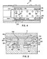
- a plurality of hydrostatic pads 210 shown in FIGS. 3 and 4, are formed in surfaces 202 of carriage 150 proximate each corner thereof. Pads 210 are elongated as shown more clearly in FIG. 4 and are of an appropriate and relatively shallow depth for hydrostatic purposes. It should be noted that pads 210a are of a greater elongation than the other pads 210 to provide extra fluid support for grinding wheel 130 at that location on workhead 140.
- An opening or port 230 opens into each pad 210, 210a and extends therefrom into fluid passageways 232 and 234, shown in FIG. 3, which terminate respectively at couplings 236 of a size and configuration to accept fluid conduits 238, the other ends of which are connected to a source of hydrostatic fluid such as a manifold, pump or reservoir (not shown) of conventional construction and operation. Suitable and conventional controls are provided to develop and maintain a fluid pressure appropriate for relatively stiff hydrostatic bearings.
- Pads 210, 210a correspond to pads 310, shown in FIG. 5, of a part A of the schematic conventional hydrostatic bearing arrangement of FIG. 5 which is provided to better understand the instant invention in comparison to conventional hydrostatic bearing arrangements.
- Fluid passageways 312 extend from pads 310 to another fluid passageway 314 which receives hydrostatic fluid at entries 316 from a suitable source of fluid appropriate for hydrostatic bearing uses and under suitable pressures and controls. Fluid from pads 310 forms a hydrostatic bearing between facing surfaces 320 of part A and 322 of part B so that part A can be moved in the direction of arrows X-X with respect to part B (i.e. into and out of the figure). The greater the fluid pressure the stiffer the hydrostatic bearing.
- the hydrostatic bearing pads 310 may be isolated from the fluid passageways 312 and 314 by conventional restrictors (not shown) to prevent the system from locking up.
- Hydrostatic bearings however, must be pre-loaded to - maintain an appropriate gap spacing between the opposed bearing surfaces. If the gap is too narrow the bearing will not function properly and if the gap is too large the fluid will simply pour out and the bearing will lose its stiffness.
- a "pre-load” is provided by fabricating a set of "pre-load” surfaces 330, 332 with fluid pads 334 formed in the surface 330. Fluid passageways 336, 338 direct the hydrostatic fluid to "pre-load" pads 334.
- the fluid pressure provided by pads 310 act against surfaces 322 of part B and the reactive forces generated thereby act to separate parts A and B, but if part B is fixedly disposed then those forces will tend to move part A away from part B, modified to a slight degree by the weight of part A.
- the "pre-load” forces generated by fluid pressure acting against surfaces 332 of part B generate reactive forces between surfaces 330, 332 which tend to draw part A towards part B.
- a controlled "pre-load” can thus provide an effective control for the gap spacing between the bearing surfaces of a hydrostatic bearing.
- linear motors such as the one shown in FIG. 6 and linear motor 174 of the instant invention, may generate strong attractive forces between the primary drive means and the secondary drive means.
- the instant invention provides its own “pre-load” for the hydrostatic bearings and eliminates the requirement for "pre-load” surfaces, hydrostatic pads, passageways and fluid for those "pre-load” pads and passageways.
- Linear motor 174 of the instant invention has thus been selected to provide an attractive force between the primary 170, carried by tool carriage 150, and secondary drive means 172, fixedly carried by slideway 160, which when augmented by the force from the weight of the workhead 140, provides an appropriate and suitable "pre-load" for hydrostatic bearings 200.
- linear motor 174 generates an attractive force of approximately 7,000 lbs.
- Linear motors which generate greater or lesser attractive forces between their respective primaries and secondaries may also be utilized depending upon the required stiffness of the hydrostatic bearing(s). Greater attractive forces permit greater fluid pressure for hydrostatic bearings and thus stiffer hydrostatic bearings.
- Additional hydrostatic bearings 300 are provided between vertical surfaces 302 of tool carriage 150 and vertical surfaces 304 of slideway 160.
- Hydrostatic pads 310 similar to pads 210 but not necessarily of the same circumferential configuration are formed in vertical surfaces 302 either at the respective ends of the carriage 150 or so as to be distributed from end to end thereof.
- Suitable hydrostatic fluid is provided to pads 310 through ports and passageways 320 from an appropriate supply of hydrostatic fluid under control from suitable conventional hydrostatic fluid pumps and controls.
- the hydrostatic fluids which exit bearings 200 and 300 drain into cavity 350 provided in slideway 162 and then drain therefrom through a conduit 352 into a reservoir 360 which may be equipped with suitable and appropriate circulating pumps and controls to maintain the desired pressure for hydrostatic bearings 200 and 300. If desired attractive forces of the type described above for bearings 200 may also be provided for either or both hydrostatic bearings 300 to "pre-load" those bearings.
- hydrostatic pads may be provided for pads 210, 210a, for damping purposes with respect to bearings 200, but arranged and positioned as though utilized for "pre-load” purposes. Suitable fluid for hydrostatic uses would be supplied to such damping pads through suitably provided passageways. Moreover, and if forces additional to the attractive forces of the linear motor 174 are required, the further hydrostatic pads may be utilized for "pre-load” purposes as well as or instead of for damping purposes.
Landscapes
- Engineering & Computer Science (AREA)
- Mechanical Engineering (AREA)
- General Engineering & Computer Science (AREA)
- Machine Tool Units (AREA)
- Magnetic Bearings And Hydrostatic Bearings (AREA)
- Turning (AREA)
- Bearings For Parts Moving Linearly (AREA)
- Auxiliary Devices For Machine Tools (AREA)
- Moulds For Moulding Plastics Or The Like (AREA)
- Replacement Of Web Rolls (AREA)
- Moulding By Coating Moulds (AREA)
Abstract
Description
Claims (35)
- A carriage drive and mounting for a carriage (150) and slideway (160), wherein said carriage (150) is carried by said slideway (160) for movement along said slideway between a first slideway location and a second slideway location and various slideway locations therebetween, comprising:(a) linear motor drive means (174) including a primary drive means (170) and a secondary drive means (172) one of which is carried by said carriage and the other of which is carried by said slideway;(b) said carriage including a first hydrostatic bearing surface (202) and said slideway including a second hydrostatic bearing surface (202);(c) hydrostatic fluid means providing hydrostatic fluid for said first hydrostatic bearing surface (202) and said second hydrostatic bearing surface (202);(d) said first hydrostatic bearing surface and said second hydrostatic bearing surface and said hydrostatic fluid means coacting to provide a hydrostatic bearing means between said carriage and said slideway to facilitate movement of said carriage; and(e) said primary drive means (170) and said secondary drive means (172) of said linear motor drive means (174) coacting to provide a predetermined attractive force of predetermined magnitude and predetermined direction and which facilitates functioning of said hydrostatic bearing means.
- A carriage drive and mounting as recited in claim 1, wherein said primary drive means (170) is carried by said carriage (150) and said secondary drive means (172) is carried by said slideway (160).
- A carriage drive and mounting as recited in claim 2, wherein said secondary drive means (172) extends from said first slideway location to said second slideway location.
- A carriage drive and mounting as recited in claim 3, wherein said secondary drive (172) means includes a plurality of permanent magnet plates and said primary drive means includes an electromagnet.
- A carriage drive and mounting as recited in claim 2, wherein said first hydrostatic bearing surface (202) includes a plurality of hydrostatic fluid pads (210).
- A carriage drive and mounting as recited in claim 5, wherein a pair of said plurality of hydrostatic fluid pads (210) are disposed proximate each end of said hydrostatic bearing surface (202).
- A carriage drive and mounting as recited in claim 6, wherein said first hydrostatic bearing surface includes a pair of spaced coplanar surfaces (202) provided on said carriage (150) for coaction with a corresponding pair of spaced coplanar surfaces (152) provided on said slideway (160).
- A carriage drive and mounting as recited in claim 7, wherein said coplanar surfaces of said carriage and said slideway are horizontally disposed. 1
- A carriage drive and mounting as recited in claim 2, wherein said predetermined direction of said predetermined attractive force is opposite to a direction of a predetermined hydrostatic force of said hydrostatic bearing means.
- A carriage drive and mounting as recited in claim 9, wherein said predetermined attractive force comprises a pre-load force for said hydrostatic bearing means.
- A carriage drive and mounting as recited in claim 10, further comprising second hydrostatic bearing means (300) acting in direction perpendicular to said first hydrostatic bearing means (200).
- A carriage drive and mounting as recited in claim 2, wherein said carriage and said carriage drive are for a tool carriage of a machine tool.
- A carriage drive and mounting as recited in claim 12, wherein said machine tool is a grinding machine.
- A carriage drive and mounting as recited in claim 2, wherein said carriage and said carriage drive are for a workpiece carriage of a machine tool.
- A carriage drive and mounting as recited in claim 14, wherein said machine tool is a grinding machine..
- A carriage drive and mounting as recited in claim 2, wherein said carriage and carriage drive support a tool carriage of a machine tool.
- A carriage drive and mounting as recited in claim 16, wherein said machine tool is a grinding machine.
- A machine tool a carriage drive and mounting for a carriage and slideway as claimed in any preceding claim.
- A method of mounting and driving a carriage on a slideway wherein said carriage is to be moved between a first slideway location and a second slideway location and a plurality of slideway locations therebetween, comprising the steps of:(a) providing a linear motor means (174) having a primary drive means (170) and a secondary drive means (172) secondary and said secondary drive means which has an attractive force between said primary drive means and said secondary drive means to operate between said carriage and said slideway;(b) providing a hydrostatic bearing means (202) between said carriage and said slideway; and(c) utilizing said attractive force between said primary drive means and said secondary drive means of said linear motor to pre-load said hydrostatic bearing.
- A method as recited in claim 19, comprising the further step of carrying said primary drive means by said carriage and carrying said secondary drive means by said slideway.
- A method as recited in claim 20, further comprising the step of providing said secondary drive means extending from said first slideway location to said second slideway location.
- A method as recited in claim 21, further comprising the steps of providing a plurality of permanent magnet plates as said secondary drive means and providing an electromagnet as said primary drive means.
- A method as recited in claim 21, further comprising the step of providing a plurality of hydrostatic fluid pads (210) in said first hydrostatic bearing surface.
- A method as recited in claim 23, further comprising the step of providing a pair of said plurality of hydrostatic fluid pads (210) proximate each end of said hydrostatic bearing surface.
- A method as recited in claim 24, further comprising the steps of:providing said first hydrostatic bearing surface with a pair of spaced coplanar surfaces (202) on said carriage; andproviding said slideway with a corresponding pair of spaced coplanar surfaces (152) for coaction with said pair of spaced coplanar surfaces on said carriage.
- A method as recited in claim 25, further comprising the step of disposing said coplanar surfaces of said carriage and said slideway horizontally.
- A method as recited in claim 20, further comprising the step of providing said predetermined direction of said predetermined attractive force so as to be opposite a direction of a predetermined hydrostatic force of said hydrostatic bearing means.
- A method as recited in claim 27, further comprising the steps of providing said predetermined attractive force to comprise a pre-load force for said hydrostatic bearing means.
- A method as recited in claim 28, further comprising the steps of providing a second hydrostatic bearing means (300) acting in a direction perpendicular to said first hydrostatic bearing means.
- A method as recited in claim 20, further comprising the steps of providing said carriage and said carriage drive for a tool carriage of a machine tool.
- A method as recited in claim 30, wherein said machine tool is a grinding machine.
- A method as recited in claim 20, further comprising the step of supporting a tool carriage (150) of a machine tool with said carriage and carriage drive.
- A method as recited in claim 19, wherein said machine tool is a grinding machine.
- A method as recited in claim 20, further comprising the step of providing a tool carriage of a machine tool with said carriage and carriage drive.
- A method as recited in claim 34, wherein said machine tool is a grinding machine.
Applications Claiming Priority (3)
| Application Number | Priority Date | Filing Date | Title |
|---|---|---|---|
| US1803296P | 1996-05-21 | 1996-05-21 | |
| US18032P | 1996-05-21 | ||
| PCT/US1997/008183 WO1997044158A2 (en) | 1996-05-21 | 1997-05-20 | Drive and support for machine tools |
Publications (4)
| Publication Number | Publication Date |
|---|---|
| EP0907462A1 EP0907462A1 (en) | 1999-04-14 |
| EP0907462A4 EP0907462A4 (en) | 2002-02-06 |
| EP0907462B1 true EP0907462B1 (en) | 2005-11-30 |
| EP0907462B9 EP0907462B9 (en) | 2006-07-19 |
Family
ID=21785894
Family Applications (1)
| Application Number | Title | Priority Date | Filing Date |
|---|---|---|---|
| EP97925568A Expired - Lifetime EP0907462B9 (en) | 1996-05-21 | 1997-05-20 | Drive and support for machine tools |
Country Status (9)
| Country | Link |
|---|---|
| EP (1) | EP0907462B9 (en) |
| JP (1) | JP2000512216A (en) |
| KR (1) | KR100445689B1 (en) |
| AT (1) | ATE311272T1 (en) |
| AU (1) | AU3066997A (en) |
| BR (1) | BR9714611A (en) |
| CA (1) | CA2255565C (en) |
| DE (1) | DE69734771T2 (en) |
| WO (1) | WO1997044158A2 (en) |
Families Citing this family (5)
| Publication number | Priority date | Publication date | Assignee | Title |
|---|---|---|---|---|
| JP4016561B2 (en) | 2000-01-17 | 2007-12-05 | 株式会社ジェイテクト | Guide mechanism for sliding bodies in machine tools |
| WO2005078909A1 (en) * | 2004-02-11 | 2005-08-25 | Siemens Aktiengesellschaft | Aerostatic linear guide for a carriage driven by a linear motor |
| JP4917281B2 (en) * | 2005-06-29 | 2012-04-18 | 株式会社岡本工作機械製作所 | Table feed mechanism for machine tools |
| JP4508176B2 (en) * | 2006-10-13 | 2010-07-21 | 株式会社ジェイテクト | Guide mechanism for sliding bodies in machine tools |
| CN105904299A (en) * | 2016-05-11 | 2016-08-31 | 周玉红 | High-precision smoothing assembly for flatness of steel plate |
Family Cites Families (5)
| Publication number | Priority date | Publication date | Assignee | Title |
|---|---|---|---|---|
| FR2488353A1 (en) * | 1980-08-07 | 1982-02-12 | Cermo | HYDROSTATIC SUPPORT DEVICE |
| US4985651A (en) * | 1987-10-19 | 1991-01-15 | Anwar Chitayat | Linear motor with magnetic bearing preload |
| JPH03149413A (en) * | 1989-11-06 | 1991-06-26 | Toshiba Corp | Fluid bearing guiding device |
| JP3031940B2 (en) * | 1990-02-21 | 2000-04-10 | キヤノン株式会社 | Travel guide device |
| US5098203A (en) * | 1991-03-11 | 1992-03-24 | Contraves Goerz Corporation | Bearing system |
-
1997
- 1997-05-20 CA CA002255565A patent/CA2255565C/en not_active Expired - Lifetime
- 1997-05-20 BR BR9714611-0A patent/BR9714611A/en active Search and Examination
- 1997-05-20 AU AU30669/97A patent/AU3066997A/en not_active Abandoned
- 1997-05-20 KR KR10-1998-0709564A patent/KR100445689B1/en not_active Expired - Fee Related
- 1997-05-20 JP JP09542518A patent/JP2000512216A/en active Pending
- 1997-05-20 DE DE69734771T patent/DE69734771T2/en not_active Expired - Lifetime
- 1997-05-20 EP EP97925568A patent/EP0907462B9/en not_active Expired - Lifetime
- 1997-05-20 AT AT97925568T patent/ATE311272T1/en not_active IP Right Cessation
- 1997-05-20 WO PCT/US1997/008183 patent/WO1997044158A2/en not_active Ceased
Also Published As
| Publication number | Publication date |
|---|---|
| BR9714611A (en) | 2001-02-13 |
| KR20000016003A (en) | 2000-03-25 |
| EP0907462A4 (en) | 2002-02-06 |
| EP0907462A1 (en) | 1999-04-14 |
| DE69734771D1 (en) | 2006-01-05 |
| WO1997044158A3 (en) | 1998-07-02 |
| AU3066997A (en) | 1997-12-09 |
| DE69734771T2 (en) | 2006-10-19 |
| JP2000512216A (en) | 2000-09-19 |
| KR100445689B1 (en) | 2004-11-03 |
| EP0907462B9 (en) | 2006-07-19 |
| CA2255565A1 (en) | 1997-11-27 |
| CA2255565C (en) | 2003-08-05 |
| ATE311272T1 (en) | 2005-12-15 |
| WO1997044158A2 (en) | 1997-11-27 |
Similar Documents
| Publication | Publication Date | Title |
|---|---|---|
| US4985651A (en) | Linear motor with magnetic bearing preload | |
| US4834353A (en) | Linear motor with magnetic bearing preload | |
| EP0265758A2 (en) | Surface grinding machine | |
| US6110010A (en) | Drive and support for machine tools | |
| US8056453B2 (en) | Fast tool servo | |
| KR100483738B1 (en) | Grinding machine and grinding method | |
| EP0907462B9 (en) | Drive and support for machine tools | |
| WO1997044158A9 (en) | Drive and support for machine tools | |
| EP0777546A4 (en) | Cnc machining system | |
| JPS6117613B2 (en) | ||
| CN205588077U (en) | Large -scale bent axle follow -up grinding machine | |
| US5669600A (en) | X-Y table | |
| JP3500411B2 (en) | Feeding mechanism of wheel head in grinding machine | |
| CN216371060U (en) | Belt-driven full-static-pressure workbench | |
| JP3290087B2 (en) | Positioning device using hydrostatic bearing | |
| JP3532133B2 (en) | Work table device | |
| JP4358385B2 (en) | Guide device for moving body in machine tool | |
| JP2002178239A (en) | Table feeder for machine tool | |
| JPH0694031A (en) | Slide device | |
| JP2513374B2 (en) | Orthogonal bidirectional movement table device | |
| JP3088833U (en) | Moving table device and machine tool using the same | |
| JP7744180B2 (en) | Wire saw | |
| JP3857398B2 (en) | Machine Tools | |
| CN113967845A (en) | Belt-driven full-static-pressure workbench | |
| CN119634785A (en) | An ultra-precision five-axis prism milling machine |
Legal Events
| Date | Code | Title | Description |
|---|---|---|---|
| PUAI | Public reference made under article 153(3) epc to a published international application that has entered the european phase |
Free format text: ORIGINAL CODE: 0009012 |
|
| 17P | Request for examination filed |
Effective date: 19981118 |
|
| AK | Designated contracting states |
Kind code of ref document: A1 Designated state(s): AT BE CH DE DK ES FI FR GB GR IE IT LI LU MC NL PT SE |
|
| A4 | Supplementary search report drawn up and despatched |
Effective date: 20011227 |
|
| AK | Designated contracting states |
Kind code of ref document: A4 Designated state(s): AT BE CH DE DK ES FI FR GB GR IE IT LI LU MC NL PT SE |
|
| RIC1 | Information provided on ipc code assigned before grant |
Free format text: 7B 24B 49/00 A, 7B 24B 7/07 B, 7H 02K 41/02 B, 7B 23Q 1/38 B, 7B 23Q 5/28 B |
|
| 17Q | First examination report despatched |
Effective date: 20021220 |
|
| GRAP | Despatch of communication of intention to grant a patent |
Free format text: ORIGINAL CODE: EPIDOSNIGR1 |
|
| GRAS | Grant fee paid |
Free format text: ORIGINAL CODE: EPIDOSNIGR3 |
|
| GRAA | (expected) grant |
Free format text: ORIGINAL CODE: 0009210 |
|
| AK | Designated contracting states |
Kind code of ref document: B1 Designated state(s): AT BE CH DE DK ES FI FR GB GR IE IT LI LU MC NL PT SE |
|
| PG25 | Lapsed in a contracting state [announced via postgrant information from national office to epo] |
Ref country code: NL Free format text: LAPSE BECAUSE OF FAILURE TO SUBMIT A TRANSLATION OF THE DESCRIPTION OR TO PAY THE FEE WITHIN THE PRESCRIBED TIME-LIMIT Effective date: 20051130 Ref country code: LI Free format text: LAPSE BECAUSE OF FAILURE TO SUBMIT A TRANSLATION OF THE DESCRIPTION OR TO PAY THE FEE WITHIN THE PRESCRIBED TIME-LIMIT Effective date: 20051130 Ref country code: FI Free format text: LAPSE BECAUSE OF FAILURE TO SUBMIT A TRANSLATION OF THE DESCRIPTION OR TO PAY THE FEE WITHIN THE PRESCRIBED TIME-LIMIT Effective date: 20051130 Ref country code: CH Free format text: LAPSE BECAUSE OF FAILURE TO SUBMIT A TRANSLATION OF THE DESCRIPTION OR TO PAY THE FEE WITHIN THE PRESCRIBED TIME-LIMIT Effective date: 20051130 Ref country code: BE Free format text: LAPSE BECAUSE OF FAILURE TO SUBMIT A TRANSLATION OF THE DESCRIPTION OR TO PAY THE FEE WITHIN THE PRESCRIBED TIME-LIMIT Effective date: 20051130 Ref country code: AT Free format text: LAPSE BECAUSE OF FAILURE TO SUBMIT A TRANSLATION OF THE DESCRIPTION OR TO PAY THE FEE WITHIN THE PRESCRIBED TIME-LIMIT Effective date: 20051130 |
|
| REG | Reference to a national code |
Ref country code: GB Ref legal event code: FG4D Ref country code: CH Ref legal event code: EP |
|
| REG | Reference to a national code |
Ref country code: IE Ref legal event code: FG4D |
|
| REF | Corresponds to: |
Ref document number: 69734771 Country of ref document: DE Date of ref document: 20060105 Kind code of ref document: P |
|
| PG25 | Lapsed in a contracting state [announced via postgrant information from national office to epo] |
Ref country code: SE Free format text: LAPSE BECAUSE OF FAILURE TO SUBMIT A TRANSLATION OF THE DESCRIPTION OR TO PAY THE FEE WITHIN THE PRESCRIBED TIME-LIMIT Effective date: 20060228 Ref country code: GR Free format text: LAPSE BECAUSE OF FAILURE TO SUBMIT A TRANSLATION OF THE DESCRIPTION OR TO PAY THE FEE WITHIN THE PRESCRIBED TIME-LIMIT Effective date: 20060228 Ref country code: DK Free format text: LAPSE BECAUSE OF FAILURE TO SUBMIT A TRANSLATION OF THE DESCRIPTION OR TO PAY THE FEE WITHIN THE PRESCRIBED TIME-LIMIT Effective date: 20060228 |
|
| PG25 | Lapsed in a contracting state [announced via postgrant information from national office to epo] |
Ref country code: ES Free format text: LAPSE BECAUSE OF FAILURE TO SUBMIT A TRANSLATION OF THE DESCRIPTION OR TO PAY THE FEE WITHIN THE PRESCRIBED TIME-LIMIT Effective date: 20060313 |
|
| PG25 | Lapsed in a contracting state [announced via postgrant information from national office to epo] |
Ref country code: PT Free format text: LAPSE BECAUSE OF FAILURE TO SUBMIT A TRANSLATION OF THE DESCRIPTION OR TO PAY THE FEE WITHIN THE PRESCRIBED TIME-LIMIT Effective date: 20060502 |
|
| PG25 | Lapsed in a contracting state [announced via postgrant information from national office to epo] |
Ref country code: IE Free format text: LAPSE BECAUSE OF NON-PAYMENT OF DUE FEES Effective date: 20060522 |
|
| PG25 | Lapsed in a contracting state [announced via postgrant information from national office to epo] |
Ref country code: MC Free format text: LAPSE BECAUSE OF NON-PAYMENT OF DUE FEES Effective date: 20060531 |
|
| NLV1 | Nl: lapsed or annulled due to failure to fulfill the requirements of art. 29p and 29m of the patents act | ||
| ET | Fr: translation filed | ||
| REG | Reference to a national code |
Ref country code: CH Ref legal event code: PL |
|
| REG | Reference to a national code |
Ref country code: GB Ref legal event code: 732E |
|
| PLBE | No opposition filed within time limit |
Free format text: ORIGINAL CODE: 0009261 |
|
| STAA | Information on the status of an ep patent application or granted ep patent |
Free format text: STATUS: NO OPPOSITION FILED WITHIN TIME LIMIT |
|
| REG | Reference to a national code |
Ref country code: FR Ref legal event code: TP |
|
| 26N | No opposition filed |
Effective date: 20060831 |
|
| REG | Reference to a national code |
Ref country code: IE Ref legal event code: MM4A |
|
| PG25 | Lapsed in a contracting state [announced via postgrant information from national office to epo] |
Ref country code: LU Free format text: LAPSE BECAUSE OF NON-PAYMENT OF DUE FEES Effective date: 20060520 |
|
| REG | Reference to a national code |
Ref country code: FR Ref legal event code: PLFP Year of fee payment: 19 |
|
| REG | Reference to a national code |
Ref country code: FR Ref legal event code: PLFP Year of fee payment: 20 |
|
| PGFP | Annual fee paid to national office [announced via postgrant information from national office to epo] |
Ref country code: GB Payment date: 20160527 Year of fee payment: 20 Ref country code: DE Payment date: 20160527 Year of fee payment: 20 |
|
| PGFP | Annual fee paid to national office [announced via postgrant information from national office to epo] |
Ref country code: FR Payment date: 20160530 Year of fee payment: 20 Ref country code: IT Payment date: 20160520 Year of fee payment: 20 |
|
| REG | Reference to a national code |
Ref country code: DE Ref legal event code: R071 Ref document number: 69734771 Country of ref document: DE |
|
| REG | Reference to a national code |
Ref country code: GB Ref legal event code: PE20 Expiry date: 20170519 |
|
| PG25 | Lapsed in a contracting state [announced via postgrant information from national office to epo] |
Ref country code: GB Free format text: LAPSE BECAUSE OF EXPIRATION OF PROTECTION Effective date: 20170519 |