EP0907404B1 - Air assist aerator/mixer - Google Patents
Air assist aerator/mixer Download PDFInfo
- Publication number
- EP0907404B1 EP0907404B1 EP97921496A EP97921496A EP0907404B1 EP 0907404 B1 EP0907404 B1 EP 0907404B1 EP 97921496 A EP97921496 A EP 97921496A EP 97921496 A EP97921496 A EP 97921496A EP 0907404 B1 EP0907404 B1 EP 0907404B1
- Authority
- EP
- European Patent Office
- Prior art keywords
- propeller
- shaft
- drive shaft
- compressed air
- air
- Prior art date
- Legal status (The legal status is an assumption and is not a legal conclusion. Google has not performed a legal analysis and makes no representation as to the accuracy of the status listed.)
- Expired - Lifetime
Links
Images


Classifications
-
- B—PERFORMING OPERATIONS; TRANSPORTING
- B01—PHYSICAL OR CHEMICAL PROCESSES OR APPARATUS IN GENERAL
- B01F—MIXING, e.g. DISSOLVING, EMULSIFYING OR DISPERSING
- B01F23/00—Mixing according to the phases to be mixed, e.g. dispersing or emulsifying
- B01F23/20—Mixing gases with liquids
- B01F23/23—Mixing gases with liquids by introducing gases into liquid media, e.g. for producing aerated liquids
- B01F23/234—Surface aerating
- B01F23/2342—Surface aerating with stirrers near to the liquid surface, e.g. partially immersed, for spraying the liquid in the gas or for sucking gas into the liquid, e.g. using stirrers rotating around a horizontal axis or using centrifugal force
-
- B—PERFORMING OPERATIONS; TRANSPORTING
- B01—PHYSICAL OR CHEMICAL PROCESSES OR APPARATUS IN GENERAL
- B01F—MIXING, e.g. DISSOLVING, EMULSIFYING OR DISPERSING
- B01F27/00—Mixers with rotary stirring devices in fixed receptacles; Kneaders
- B01F27/60—Mixers with rotary stirring devices in fixed receptacles; Kneaders with stirrers rotating about a horizontal or inclined axis
Definitions
- the present invention relates to an aerator for treatment of fluid. More particularly, the present invention relates to an air assisted propeller aerator apparatus which efficiently mixes and improves the dissolved oxygen content in a fluid.
- Aeration processes are utilized in the treatment of fluid for the purpose of mixing and increasing the dissolved oxygen (DO) content of the fluid.
- DO dissolved oxygen
- bacteria and other micro-organisms are supplied with oxygen to breakdown organic matter within the waste water in a purification process.
- aeration processes are used in the treatment of water to meet the dissolved oxygen requirements for supporting fish life and other aquatic organisms.
- Known aeration apparatuses include surface aerators, diffuser/blowers, and rotor aerators.
- Surface aerators pump water upward and throw the water into the air.
- Surface aeration systems require high horse power and consume high amounts of energy in pumping water against the force of gravity.
- blower/diffuser systems compressed air is introduced through diffusers at the bottom of a basin. Higher horse power is required to overcome the water head resistance. Oxygen rises vertically and escapes quickly before effective dispersion into the water can take place.
- Rotor aerators consist of rotating aerators positioned at the surface of the water receiving treatment. Rotor systems have been known to be expensive to maintain and are high in energy consumption. They cast water into the air, creating an aerosol environment which releases offending odors into the air.
- aeration apparatus is an aspirator type aerator.
- These devices use an electrical motor driven rotating propeller disposed below the surface of the substance being treated.
- the propeller draws in atmospheric air from an intake port through a draft tube and discharges it into the substance, e.g., the waste water being treated or the water containing marine life.
- Propeller type aerators may be operated generally horizontally, creating a horizontal rather than vertical flow pattern within a treatment basin.
- the US-A-2,928,661 relates to gas and liquid contact apparatus, and particularly to mixing an aerating apparatus for use in the treatment of sewage by the activated sludge process. It comprises a fixed motor with a drive shaft.
- the drive shaft has two propellers and two aspirator tubes each having an outlet vent. The two propellers create a fluid stream which causes the emitted air to be held in the fluid stream.
- the US-A-3,400,918 discloses a sewage aerator including a treatment tank with a covered enclosure located on top thereof.
- a sealed casing or housing is mounted in the enclosure and an electric motor with a stator and rotor is positioned therein.
- a motor shaft is rotatably mounted on bearings in the upper and lower end walls of the motor casing and has a lower extension which extends beyond the surface of sewage in the tank.
- An axially extending passage is provided in the shaft and extension and conduit means connect the upper end of the passage to atmosphere.
- Aspirator tubes which extend in a radial direction connect the lower end of the passage to the interior of the tank and upon rotation of the shaft cause an aspirating effect to draw air down the passage and into the tank. Screw means on the shaft serve to agitate the sewage.
- the US-A-3,465,706 discloses an addition to an outboard drive unit of the type including an upstanding rack in the lower portion of which a horizontal propeller shaft is drawn out having a propeller thereon and which also includes an underwater exhaust outlet disposed in the area of the propeller but rearwardly thereof and at a point spaced laterally of the access of rotation of the propeller, the addition including means whereby air under atmospheric pressure is supplied to the area disposed immediately behind the propeller and in alignment with its access of rotation and thus may be discharged into the ambient water.
- the US-A-4,240,990 discloses an apparatus for mixing a gas and a liquid.
- the apparatus is comprised of a hollow outer housing and a hollow inner tube received for rotary motion within the outer housing.
- a motor is attached to the outer housing adjacent a first end thereof and is drivingly coupled to a first end of the inner tube.
- the inner tube has a support tube which extends beyond the second end of the outer housing.
- Propeller blades are attached to the support tube for rotation therewith.
- An inlet is formed in the inner tube for admitting a gas to the hollow interior of the inner tube for admitting a gas to the hollow interior of the inner tube.
- the support tube has a diffusion section that extends below the propeller blades.
- the US-A-4,774,031 discloses an aerator which includes a hollow outer tube and a hollow inner tube rotatably supported therein.
- the inner tube is drivingly connected to a drive shaft of the motor.
- a mounting flange extends from a first end of the outer tube and a mounting bracket is interposed between the mounting flange and the motor.
- the mounting bracket and mounting flange are removably attached to the motor.
- a propeller is attached to the second end of the inner tube.
- the US-A-4,844,816 discloses a spiral tube aerator for waste aeration which includes a shaft rotatably driven by a motor, the shaft carrying a mixing chamber, an air channel extending along the shaft and opening through at least one outlet of the mixing member, a blower for delivering air through the air channel, the mixing chamber being submerged in waste water at least to a depth of 50 cm below the waste water upper surface, and the blower providing a pressure in the range 0-35 mbar lower than the pressure exerted by the waste water at the outlet.
- the US-A-5,300,261 discloses an apparatus for aerating a pool of liquid having a hollow, rotatable drive shaft drawn out for rotation about an access and coupled at one end to a driving motor.
- a propeller is mounted at the other end of the drive shaft.
- the propeller has a plurality of hollow blades in communication with an internal aerating fluid passage in the drive shaft.
- a plurality of air inlets is provided in the drive shaft and at least one outlet port is provided in each blade at the sew of highest negative pressure resulting from rotation of the blade in the liquid.
- the shaft is continuously pressurized between the bearing and the seal to prevent liquid from passing through the seal should the seal become worn.
- the JP-A-06-002889 discloses a box of an outer unit which is formed of a front panel integrally molded at a front side of a product and a sealing surface by a metal plate, a fan motor fastening plate in the unit to support a panel and a resin net at a left side surface and rear surface of the product.
- the panel is clamped at the plate with screws.
- a retaining piece formed in a U-shaped section is provided at an upper end of the plate, an upper end of a heat exchanger is enclosed with a piece, and clamped at a lower part to a board of the product with four screws.
- Known propeller type aeration apparatus include US-A-4,280,911, US-A-4,741,825, US-A-4,806,251, US-A-4,844,843, US-A-4,741,870, and US-A-4,954,295.
- the above known aerators require high speed propellers to create the vacuum for drawing in atmospheric air from an intake port and discharging it into the substance. Accordingly, these known aerators use high amounts of energy to create the vacuum.
- the apparatus of the invention is constructed as claimed in claim 1, and the method of the invention is as claimed in claim 12.
- FIG. 1 shows an aeration system in accordance with the present invention generally at 10.
- Aeration system 10 includes aerator 12 coupled to compressed air source 14.
- Aerator 12 and compressed air source 14 are coupled to and supported by float support structure 16.
- Aeration system 10 provides for efficient mixing and/or aeration of water for improving the dissolved oxygen content of the water in a water treatment system.
- float support structure 16 includes a generally U-shaped float base 24 having an open end 20 and a closed end 22.
- the uniquely shaped support structure allows operation of aerator 12, while providing a platform for personnel during maintenance and testing of the aeration system.
- the float base 24 is constructed of a metallic or non-metallic frame which is filled with foam. In one embodiment, the frame is metallic.
- the float base 24 may be manufactured in halves, shown as first half 26 and second half 28. The first half 26 and second half 28 are generally symmetrical in size and shape, and may be secured together at bolted connections 30 to form the generally U-shaped float base 24.
- Float base 24 includes deck 32 which has an area suitable for stable support of personnel during testing or maintenance of the aeration equipment.
- the deck 32 is enclosed by a relatively small knee wall 34, extending up from deck 32, and located about its outside perimeter.
- the shape of deck 32 corresponds to the shape of float base 24 allowing free access to equipment supported by support structure 16.
- mounting frame 36 Secured to deck 32 is mounting frame 36 for mounting aeration equipment on support structure 16.
- mounting frame 36 includes mounting bracket 38, mounting bracket 40, mounting bracket 42, and mounting bracket 44 secured to deck 32.
- Tubular support member 46 extends between and is fixedly secured at its ends to mounting bracket 38 and mounting bracket 40.
- Tubular support member 48 extends between and is fixedly secured at its ends to mounting bracket 42 and mounting bracket 44.
- Stabilizing bracket 50 is connected between tubular support member 46 and tubular support member 48 proximate the open end 20 of support structure 16, providing structural integrity to mounting frame 36.
- Compressor mounting plate 52 is connected between tubular support member 46 and tubular support member 48 proximate the closed end 22 of support structure 16. Compressor mounting plate 52 supports compressed air source 14 and provides further stabilization to support structure 16.
- Motor mounting bracket 54 Extending proximate the center of tubular support member 46 is motor mounting bracket 54, and extending proximate the center of tubular support member 48 is motor mounting bracket 56.
- Motor mounting bracket 54 and motor mounting bracket 56 allow aerator 12 to be movably suspended over the U-shaped opening in float base 24.
- a side elevational view of aeration system 10 is generally shown.
- Aerator 12 is rotatably coupled to support structure 16 (using motor mounting bracket 54 and motor mounting bracket 56).
- aerator 12 may be movably/selectively mounted between a generally vertical position A and a generally horizontal position (not shown).
- Aerator 12 is also shown in an intermediate position B.
- Aerator 12 may be pulled up into a generally horizontal position (and supported from stabilizing bracket 50) allowing maintenance to be performed on the aerator 12.
- Aerator 12 generally includes a motor 62 coupled to a shaft system 64 which, during operation, extends below support structure 16. Coupled to the end of shaft system 64 is propeller system 66.
- motor 62 is an electric motor having electrical box 68 for connection to an electrical power source (not shown), indicated at 69.
- the shaft system 64 is coupled to the compressed air source 14 using flexible air hose 70. With this flexible connection, aerator 12 may be moved or positioned between the generally vertical position A and the generally horizontal position while maintaining the connection to compressed air source 14.
- compressed air source 14 is an electric powered air compressor having a motor 72 and an air system 74 extending above the motor 72. Air compressor motor 72 is coupled to an electrical power source (not shown). Referring to Fig.
- motor 62 is an electric motor, which may typically range in power between 1 and 100 horsepower. It is also recognized that motor 62 may be much larger than 100 horsepower. Motor 62 has a rotatable power shaft 82 extending therefrom.
- Shaft system 64 includes a drive shaft 84 positioned within housing 86.
- Housing 86 includes compressed air opening 88, which, when assembled, is in communication with compressed air source 14 through flexible air hose 70.
- Drive shaft 84 is rotatably positioned within housing 86.
- Drive shaft 84 is a generally tubular member, and includes a first end 90 and a second end 92. Located at the first end 90 is a universal joint 93. Extending into the interior of the shaft 84 is air intake hole 94. In one preferred embodiment, air intake hole 94 is located proximate the drive shaft first end 90. It is also recognized that shaft 84 may include several air intake holes 94.
- the drive shaft second end 92 includes threads 96 for connection to propeller system 66.
- the shaft system housing 86 includes a flange 98 which is bolted to the casing of motor 62 through mounting plate 100.
- the first end 90 of drive shaft 84 extends through an opening 102 in mounting plate 100, and is coupled to the motor rotatable power shaft 82.
- Mounting plate 100 further includes extension 104 for rotatable connection to motor mounting bracket 54 and extension 106 for rotatable connection to motor mounting bracket 56.
- the drive shaft air intake hole 94 When assembled, the drive shaft air intake hole 94 generally aligns with housing compressed air opening 88. As drive shaft 84 is rotated about its longitudinal axis, compressed air may pass through compressed air opening 88, and access the hollow shaft of drive shaft 84 through air intake hole 94, exiting drive shaft second end 92.
- Propeller system 66 includes primary propeller 108, secondary propeller 110, and atomizer 112.
- Primary propeller 108 includes primary blades 114 extending outward from a hollow primary propeller shaft 116.
- the primary propeller shaft 116 is sized to fit over drive shaft second end 92.
- the primary propeller 108 is similar to a standard ship propeller.
- secondary propeller 110 includes secondary propeller blades 118 extending outward from secondary propeller shaft 120.
- the secondary propeller blades 118 are small relative to primary propeller blades 114.
- Atomizer 112 is located proximate the secondary propeller 110.
- atomizer 112 includes atomizer fin 122, atomizer fin 124, atomizer fin 126, and atomizer fin 128 (not shown) extending longitudinally from one end of secondary propeller 110, and are spaced radially about the shaft 120. As atomizer fins 122-128 extend beyond propeller shaft 120, the atomizer fins extend inward towards the central longitudinal axis of the shaft 120, to a location which is farther inward than the interior opening of the secondary propeller shaft 120.
- primary propeller 108 is positioned over the drive shaft second end 92, and is coupled to the drive shaft 84.
- Spacer 130 is partially positioned over the drive shaft second end 92 and tightened against the primary propeller shaft 116. In one embodiment, spacer 130 is screwed tight onto the drive shaft second end 92, against primary propeller shaft 116.
- spacer 130 is a tubular member having an interior diameter which is approximately equal to the interior diameter of drive shaft 84 and an outside diameter which is approximately equal to the outside diameter of primary propeller shaft 116.
- Connected to an opposite end of spacer 130 is secondary propeller 110.
- the length of spacer 130 corresponds to the distance it is desired to space the secondary propeller from the primary propeller 10B to achieve a desired propeller performance.
- the secondary propeller 110 is coupled to spacer 130 by bonding the secondary propeller shaft 120 to the end of spacer 130.
- Atomizer 112 is located at an opposite end of secondary propeller 110.
- the atomizer 112 atomizer fins 122-128 are formed integral the secondary propeller 110. It is recognized that atomizer 112 may also be formed as a separate unit and secured to the end of the secondary propeller shaft 120 or separated from the end of secondary propeller shaft 120 by an additional spacer, depending on the size of secondary propeller 110 and the desired propeller system performance characteristics.
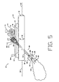
- aeration system 10 in accordance with the present invention is shown in operation.
- the aeration system 10 is located within a water basin for treatment of water 132 contained therein.
- Float support structure 16 floats on the surface of the water 132, supporting aerator 12 and compressed air source 14.
- the aerator 12 propeller system 66 is disposed within water 132 at a desired angle.
- aerator 12 When in an operational position, aerator 12 may be operated in selected modes of operation for performing a desired process, such as a mixer for a nitrification/denitrification process or an air assisted aerator.
- the aeration system 10 in accordance with the present invention is operated as an air-assisted propeller driven aspirated aerator.
- the aerator 12 operates with compressed air source 14 for maximum aeration and oxygenation efficiency.
- the aerator 12 is adjusted to the desired angle of operation relative to float support structure 16.
- Motor 62 is energized to rotate primary propeller 108 (through drive shaft 84) at a relatively low velocity. Rotating primary propeller 108 at a relatively low velocity operates the propeller 108 as a mixer of water 132, indicated by flow arrows 136.
- Compressed air source 14 provides air through drive shaft 84 to the aeration process.
- the amount of air received from compressed air source 14 is fully adjustable.
- compressed air source 14 provides compressed air to aerator 12 through flexible air hose 70. Air passes through housing 86 at opening 88. As drive shaft 84 rotates, air enters the hollow drive shaft 84 through air intake hole 94, and exits the propeller system 66 at air outlet 134.
- the secondary propeller 110 is used to diffuse the main flow of water 132 to a gently directed flow towards the atomizer 112, indicated by flow arrows 138.
- the atomizer 112 mixes the directed flow with the compressed air exiting the air outlet 134.
- the atomizer 112 shapes the air exiting air outlet 134 into fine atomized bubbles for efficiently increasing the dissolved oxygen content in the water 132.
- the fine atomized bubbles, indicated by atomization cloud 140 prolong the bubble hang time within water 132 allowing less air to escape to the surface of the water 132 and correspondingly a greater oxygen transfer rate to the water 132.
- the compressed air source 14 air pressure and/or volume, the propeller system 66 velocity, and the mounting angle of aerator 12 are fully adjustable to achieve maximum efficiency and oxygenation performance of aeration system 10. Further, the location of the atomizer 112, secondary propeller 110 and primary propeller 108 may be adjusted to be located at a predetermined distance along the line of flow for maximum performance of the propeller system 66 and corresponding oxygen transfer rate.
- the unique design of the aeration system in accordance with the present invention provides for efficient mixing and/or transfer of oxygen, improving the dissolved oxygen content of water receiving treatment.
- the aerator of the present invention requires less energy consumption corresponding to a desired oxygen transfer rate, since the propeller system no longer requires to be operated at a very high velocity rate required to create the vacuum to draw air through the aerator shaft as required in conventional type aeration systems.
- the aeration system 10 in accordance with the present invention may be operated in connection with a fluid treatment control system, making the performance characteristics fully automatically adjustable through automatic adjustment of the aerator 12 angled relative to the support structure 16, adjusting air supplied by compressed air source 14, and adjusting the operation velocity of propeller system 66.
- the velocity of propeller system 66 may be increased, creating a vacuum proximate atomizer 12, allowing aerator 12 to be used as conventional aspirator aerator as known in the art, without the assistance of compressed air. It is recognized that the pressure of the air located within drive shaft 84 may be approximately equal to the pressure present air outlet 134. Alternatively, the pressure of air located within drive shaft 84 may be greater or less than the pressure present at air outlet 134 as selectively desired for specific aerator performance.
- aerator 12 is used solely as a mixer in a nitrification/de-nitrification process without the introduction of outside air or compressed air.
- drive shaft 84 rotates primary propeller 108 at a desired speed and angle to provide the desired amount of mixing and movement of water 132 for the nitrification/de-nitrification process.
Applications Claiming Priority (3)
| Application Number | Priority Date | Filing Date | Title |
|---|---|---|---|
| US642445 | 1996-05-03 | ||
| US08/642,445 US5744072A (en) | 1996-05-03 | 1996-05-03 | Method of treating waste water |
| PCT/US1997/007469 WO1997041951A1 (en) | 1996-05-03 | 1997-05-02 | Air assist aerator/mixer |
Publications (3)
| Publication Number | Publication Date |
|---|---|
| EP0907404A1 EP0907404A1 (en) | 1999-04-14 |
| EP0907404A4 EP0907404A4 (en) | 2000-10-11 |
| EP0907404B1 true EP0907404B1 (en) | 2003-10-01 |
Family
ID=24576588
Family Applications (1)
| Application Number | Title | Priority Date | Filing Date |
|---|---|---|---|
| EP97921496A Expired - Lifetime EP0907404B1 (en) | 1996-05-03 | 1997-05-02 | Air assist aerator/mixer |
Country Status (10)
| Country | Link |
|---|---|
| US (1) | US5744072A (ja) |
| EP (1) | EP0907404B1 (ja) |
| JP (1) | JP3730665B2 (ja) |
| AU (1) | AU2752097A (ja) |
| BR (1) | BR9709049A (ja) |
| DE (1) | DE69725309T2 (ja) |
| DK (1) | DK0907404T3 (ja) |
| ES (1) | ES2208899T3 (ja) |
| PT (1) | PT907404E (ja) |
| WO (1) | WO1997041951A1 (ja) |
Families Citing this family (32)
| Publication number | Priority date | Publication date | Assignee | Title |
|---|---|---|---|---|
| DE20105706U1 (de) * | 2001-03-30 | 2001-06-28 | Kronawitter Andreas | Schwimmender Schaufelradbelüfter |
| US5821286A (en) * | 1996-05-24 | 1998-10-13 | The United States Of America As Represented By The Secretary Of The Agriculture | Biodegradable polyester and natural polymer compositions and films therefrom |
| US5868091A (en) * | 1997-02-14 | 1999-02-09 | Aeromix Systems, Inc. | Float mounted aerator having a work deck |
| WO1999065596A1 (en) * | 1998-06-19 | 1999-12-23 | Rodi Systems Corp. | Fluid treatment apparatus |
| US6609070B1 (en) | 1998-06-19 | 2003-08-19 | Rodi Systems Corp | Fluid treatment apparatus |
| US6325842B1 (en) * | 1999-04-06 | 2001-12-04 | Dean A. Caldwell | Method and apparatus for aerating |
| BE1013103A7 (nl) * | 1999-10-04 | 2001-09-04 | Aquasystems Internat N V | Menger-beluchter in gecombineerde vorm. |
| ATE297877T1 (de) * | 2000-11-08 | 2005-07-15 | Philadelphia Mixing Solutions | Verbesserter belüfter und mischer |
| US6656587B2 (en) * | 2001-05-02 | 2003-12-02 | Phillips Plastics Corporation | Composite particles |
| DE10154396A1 (de) * | 2001-07-28 | 2003-02-27 | Gerhard Moeller | Belüfter für Gewässer |
| JP2004290712A (ja) * | 2001-09-25 | 2004-10-21 | Moburon Sekkei Jimusho:Kk | 容積体の変動による水流発生機 |
| NZ528434A (en) * | 2003-09-24 | 2005-07-29 | Philadelphia Mixing Solutions | Improved aerator and mixer |
| US20050167858A1 (en) * | 2004-02-04 | 2005-08-04 | Jones Robert L. | Aerator apparatus and method of use |
| US7172177B2 (en) * | 2004-04-15 | 2007-02-06 | Aeration Industries International, Inc. | Aerator |
| US7306724B2 (en) * | 2004-04-23 | 2007-12-11 | Water Standard Co., Llc | Wastewater treatment |
| US7048260B2 (en) * | 2004-05-12 | 2006-05-23 | Aeromix Systems, Incorporated | Turbocharged aerator |
| US20060180949A1 (en) * | 2005-02-16 | 2006-08-17 | Gerrit Beusekom | Impeller draft tube, shroud, impeller and aerator |
| US7465394B2 (en) | 2006-09-05 | 2008-12-16 | Aeration Industries International, Inc. | Wastewater treatment system |
| CN101555067B (zh) * | 2008-04-09 | 2010-12-29 | 孙树林 | 回转潜浮式曝气机 |
| CN100582026C (zh) * | 2006-12-15 | 2010-01-20 | 孙建 | 潜浮式曝气机 |
| US7934705B2 (en) * | 2006-12-15 | 2011-05-03 | Sun Shulin | Multi-directional submersible floating aerator |
| US10421677B2 (en) * | 2008-01-17 | 2019-09-24 | Dale C. Barr | Systems and methods for watercraft having invasive species mitigation capability |
| US9180939B2 (en) * | 2008-01-17 | 2015-11-10 | Dale C. Barr | Systems and methods for watercraft having marine environment enhancement capability |
| DE102009055773B4 (de) * | 2009-11-25 | 2015-05-28 | Uwe von Briel | Vorrichtung zum Homogenisieren von in einer Güllegrube befindlicher Gülle |
| CN101913689A (zh) * | 2010-07-23 | 2010-12-15 | 合肥强力动物药品有限责任公司 | 多功能高效污水处理反应器 |
| CN101913688B (zh) * | 2010-07-23 | 2012-02-29 | 安徽省瑞森生物科技有限责任公司 | 多功能高效污水处理零排放系统 |
| JP5579562B2 (ja) * | 2010-09-29 | 2014-08-27 | 株式会社日立製作所 | 曝気撹拌機 |
| US9675942B1 (en) | 2013-10-15 | 2017-06-13 | Aeration Industries International, LLC. | Universal bridge and wall mounted aeration apparatus |
| CA2871812A1 (en) * | 2013-11-20 | 2015-05-20 | Hydro Engineering | Manure agitation boat |
| US10444254B2 (en) | 2014-12-18 | 2019-10-15 | Sikorsky Aircraft Corporation | Virtual tachometers based on time series filtering |
| US11596907B1 (en) | 2019-06-14 | 2023-03-07 | Aeration Industries International, Llc | Apparatus for treating fluids having improved aeration efficiency and operational durability |
| US11406943B1 (en) | 2019-06-14 | 2022-08-09 | Aeration Industries International, Llc | Apparatus for treating fluids having improved aeration efficiency and dual function operation |
Family Cites Families (32)
| Publication number | Priority date | Publication date | Assignee | Title |
|---|---|---|---|---|
| US2314624A (en) * | 1940-05-06 | 1943-03-23 | Yuba Mfg Company | Dredge hull |
| US2453155A (en) * | 1945-06-30 | 1948-11-09 | Homer B Nelson | Floating dock and wharf |
| US2876726A (en) * | 1956-06-29 | 1959-03-10 | Alces P Robishaw | Barge |
| US2928661A (en) * | 1958-06-09 | 1960-03-15 | Albert S Maclaren | Gas and liquid mixing apparatus |
| GB955879A (en) * | 1961-09-01 | 1964-04-22 | Proprietors Of Hay S Wharf Ltd | Improvements in apparatus for clearing silt and mud |
| US3349415A (en) * | 1966-01-03 | 1967-10-31 | Roger A Scholle | Sectional boat construction and hinged seat connecting means therefor |
| US3400918A (en) * | 1967-03-08 | 1968-09-10 | David S. Maclaren | Sewage aerator |
| US3465706A (en) * | 1968-02-05 | 1969-09-09 | Steve J Gwidt | Apparatus for injecting fresh air into outboard motor underwater exhaust |
| US3524629A (en) | 1968-07-29 | 1970-08-18 | Don A Culwell | Apparatus for and method of aerating liquids |
| US3478710A (en) * | 1968-07-31 | 1969-11-18 | Jack W Bethurem | Floating dock structure |
| US3650513A (en) * | 1969-04-04 | 1972-03-21 | Frank D Werner | Aeration device |
| US3755142A (en) * | 1971-05-21 | 1973-08-28 | W Whipple | Process and apparatus for the purification of a natural body of water |
| US3836130A (en) | 1972-06-23 | 1974-09-17 | Solem Machine Co | Liquid aerating apparatus |
| US4280911A (en) * | 1978-08-17 | 1981-07-28 | Aeration Industries | Method for treating water |
| US4240990A (en) * | 1979-04-10 | 1980-12-23 | Aeration Industries, Inc. | Aeration propeller and apparatus |
| US4540528A (en) | 1980-07-08 | 1985-09-10 | Haegeman Johny H | Apparatus for mixing gas and liquid |
| JPS60501590A (ja) * | 1983-10-24 | 1985-09-26 | エアレイシヨン インダストリ−ズ,インコ−ポレ−テツド | 通気装置 |
| DE3340420A1 (de) * | 1983-11-09 | 1985-05-23 | Albert Blum | Belueftungsvorrichtung fuer groessere gewaesser |
| DE3538715A1 (de) * | 1985-10-31 | 1987-05-07 | Fuchs Leonhard | Schraubenbeluefter fuer die abwasserbegasung |
| US4741825A (en) * | 1985-12-18 | 1988-05-03 | Aeration Industries, Inc. | Mobile vortex shield |
| US4806251A (en) * | 1986-09-16 | 1989-02-21 | Aeration Industries, Inc. | Oscillating propeller type aerator apparatus and method |
| US4741870A (en) * | 1987-06-26 | 1988-05-03 | Aeromix Systems, Incorporated | Apparatus for treatment of liquids |
| US4844843A (en) * | 1987-11-02 | 1989-07-04 | Rajendren Richard B | Waste water aerator having rotating compression blades |
| US4954295A (en) * | 1989-01-12 | 1990-09-04 | Aeration Industries, Inc. | Propeller aerator with peripheral injection of fluid and method of using the aerator |
| US5116501A (en) * | 1991-01-25 | 1992-05-26 | House Manufacturing, Inc. | Paddlewheel aerator drive mechanism |
| HU207669B (en) * | 1991-02-01 | 1993-05-28 | Richter Gedeon Vegyeszet | Complex mixing apparatus for dispersing gases in fluid |
| US5110510A (en) * | 1991-02-21 | 1992-05-05 | Jmo Holding, Inc. | Aeration and mixing apparatus |
| US5160667A (en) * | 1991-08-26 | 1992-11-03 | Aeromix Systems, Incorporated | Bearing protection device for liquid aerators |
| JPH062889A (ja) * | 1992-06-16 | 1994-01-11 | Matsushita Seiko Co Ltd | 空気調和機の室外ユニット |
| US5300261A (en) * | 1992-11-12 | 1994-04-05 | Richard Von Berg | Liquid aerating apparatus |
| BE1006790A3 (nl) | 1993-02-24 | 1994-12-06 | Haegeman J H | Werkwijze en inrichting voor het behandelen van water in afvalbekkens. |
| AU7648794A (en) | 1994-09-28 | 1996-04-19 | Johny Hector Haegeman | Aerator with improved efficiency |
-
1996
- 1996-05-03 US US08/642,445 patent/US5744072A/en not_active Expired - Lifetime
-
1997
- 1997-05-02 DK DK97921496T patent/DK0907404T3/da active
- 1997-05-02 PT PT97921496T patent/PT907404E/pt unknown
- 1997-05-02 DE DE69725309T patent/DE69725309T2/de not_active Expired - Fee Related
- 1997-05-02 BR BRPI9709049-2A patent/BR9709049A/pt not_active IP Right Cessation
- 1997-05-02 WO PCT/US1997/007469 patent/WO1997041951A1/en active IP Right Grant
- 1997-05-02 ES ES97921496T patent/ES2208899T3/es not_active Expired - Lifetime
- 1997-05-02 EP EP97921496A patent/EP0907404B1/en not_active Expired - Lifetime
- 1997-05-02 JP JP54006597A patent/JP3730665B2/ja not_active Expired - Lifetime
- 1997-05-05 AU AU27520/97A patent/AU2752097A/en not_active Abandoned
Also Published As
| Publication number | Publication date |
|---|---|
| US5744072A (en) | 1998-04-28 |
| DE69725309T2 (de) | 2004-07-29 |
| EP0907404A1 (en) | 1999-04-14 |
| DK0907404T3 (da) | 2004-02-09 |
| JP3730665B2 (ja) | 2006-01-05 |
| AU2752097A (en) | 1997-11-26 |
| ES2208899T3 (es) | 2004-06-16 |
| DE69725309D1 (de) | 2003-11-06 |
| PT907404E (pt) | 2003-12-31 |
| WO1997041951A1 (en) | 1997-11-13 |
| EP0907404A4 (en) | 2000-10-11 |
| BR9709049A (pt) | 2000-01-04 |
Similar Documents
| Publication | Publication Date | Title |
|---|---|---|
| EP0907404B1 (en) | Air assist aerator/mixer | |
| JPH11514578A (ja) | 空気補助式曝気装置/攪拌装置 | |
| CA1328028C (en) | Aeration method and apparatus | |
| US4817561A (en) | Aquatic aeration and filtering system | |
| US4844843A (en) | Waste water aerator having rotating compression blades | |
| EP0904148B1 (en) | Turbo aerator | |
| US4954295A (en) | Propeller aerator with peripheral injection of fluid and method of using the aerator | |
| US7172177B2 (en) | Aerator | |
| WO1997041952A9 (en) | Turbo aerator | |
| US7661660B2 (en) | Method and apparatus for aeration of a fluid | |
| US4710325A (en) | Aspirating aeration and liquid mixing apparatus | |
| JPS60501590A (ja) | 通気装置 | |
| US5676889A (en) | Apparatus for aerating and mixing liquids and/or gases | |
| JP3160057B2 (ja) | 攪拌曝気装置 | |
| JP2000107792A (ja) | 散気・攪拌装置 | |
| US20050167858A1 (en) | Aerator apparatus and method of use | |
| HU188312B (en) | Mixing aerating device | |
| US20060087047A1 (en) | Fluid mixing apparatus | |
| US7048260B2 (en) | Turbocharged aerator | |
| US20040145068A1 (en) | Method of transferring gas to a liquid by cavitation | |
| JPH07155785A (ja) | 水質浄化用高速回転空気自給曝気装置 | |
| EP0885057B1 (en) | Device for mixing gas in a liquid | |
| SU1035004A1 (ru) | Аэратор | |
| JPH09308894A (ja) | 曝気装置 | |
| JPS6330555Y2 (ja) |
Legal Events
| Date | Code | Title | Description |
|---|---|---|---|
| PUAI | Public reference made under article 153(3) epc to a published international application that has entered the european phase |
Free format text: ORIGINAL CODE: 0009012 |
|
| 17P | Request for examination filed |
Effective date: 19981112 |
|
| AK | Designated contracting states |
Kind code of ref document: A1 Designated state(s): BE DE DK ES FI FR GB GR IT NL PT SE |
|
| A4 | Supplementary search report drawn up and despatched |
Effective date: 20000825 |
|
| AK | Designated contracting states |
Kind code of ref document: A4 Designated state(s): BE DE DK ES FI FR GB GR IT NL PT SE |
|
| 17Q | First examination report despatched |
Effective date: 20020124 |
|
| GRAH | Despatch of communication of intention to grant a patent |
Free format text: ORIGINAL CODE: EPIDOS IGRA |
|
| GRAS | Grant fee paid |
Free format text: ORIGINAL CODE: EPIDOSNIGR3 |
|
| GRAA | (expected) grant |
Free format text: ORIGINAL CODE: 0009210 |
|
| AK | Designated contracting states |
Kind code of ref document: B1 Designated state(s): BE DE DK ES FI FR GB GR IT NL PT SE |
|
| REG | Reference to a national code |
Ref country code: GB Ref legal event code: FG4D |
|
| REF | Corresponds to: |
Ref document number: 69725309 Country of ref document: DE Date of ref document: 20031106 Kind code of ref document: P |
|
| REG | Reference to a national code |
Ref country code: SE Ref legal event code: TRGR |
|
| REG | Reference to a national code |
Ref country code: GR Ref legal event code: EP Ref document number: 20030405212 Country of ref document: GR |
|
| REG | Reference to a national code |
Ref country code: DK Ref legal event code: T3 |
|
| PGFP | Annual fee paid to national office [announced via postgrant information from national office to epo] |
Ref country code: PT Payment date: 20040312 Year of fee payment: 8 |
|
| PGFP | Annual fee paid to national office [announced via postgrant information from national office to epo] |
Ref country code: NL Payment date: 20040518 Year of fee payment: 8 |
|
| PGFP | Annual fee paid to national office [announced via postgrant information from national office to epo] |
Ref country code: FI Payment date: 20040521 Year of fee payment: 8 |
|
| PGFP | Annual fee paid to national office [announced via postgrant information from national office to epo] |
Ref country code: SE Payment date: 20040524 Year of fee payment: 8 |
|
| PGFP | Annual fee paid to national office [announced via postgrant information from national office to epo] |
Ref country code: DK Payment date: 20040525 Year of fee payment: 8 Ref country code: BE Payment date: 20040525 Year of fee payment: 8 |
|
| REG | Reference to a national code |
Ref country code: ES Ref legal event code: FG2A Ref document number: 2208899 Country of ref document: ES Kind code of ref document: T3 |
|
| ET | Fr: translation filed | ||
| PLBE | No opposition filed within time limit |
Free format text: ORIGINAL CODE: 0009261 |
|
| STAA | Information on the status of an ep patent application or granted ep patent |
Free format text: STATUS: NO OPPOSITION FILED WITHIN TIME LIMIT |
|
| 26N | No opposition filed |
Effective date: 20040702 |
|
| PG25 | Lapsed in a contracting state [announced via postgrant information from national office to epo] |
Ref country code: GR Free format text: LAPSE BECAUSE OF NON-PAYMENT OF DUE FEES Effective date: 20041203 |
|
| PG25 | Lapsed in a contracting state [announced via postgrant information from national office to epo] |
Ref country code: IT Free format text: LAPSE BECAUSE OF NON-PAYMENT OF DUE FEES;WARNING: LAPSES OF ITALIAN PATENTS WITH EFFECTIVE DATE BEFORE 2007 MAY HAVE OCCURRED AT ANY TIME BEFORE 2007. THE CORRECT EFFECTIVE DATE MAY BE DIFFERENT FROM THE ONE RECORDED. Effective date: 20050502 |
|
| PG25 | Lapsed in a contracting state [announced via postgrant information from national office to epo] |
Ref country code: SE Free format text: LAPSE BECAUSE OF NON-PAYMENT OF DUE FEES Effective date: 20050503 |
|
| PG25 | Lapsed in a contracting state [announced via postgrant information from national office to epo] |
Ref country code: FI Free format text: LAPSE BECAUSE OF NON-PAYMENT OF DUE FEES Effective date: 20050506 |
|
| PG25 | Lapsed in a contracting state [announced via postgrant information from national office to epo] |
Ref country code: DK Free format text: LAPSE BECAUSE OF NON-PAYMENT OF DUE FEES Effective date: 20050531 Ref country code: BE Free format text: LAPSE BECAUSE OF NON-PAYMENT OF DUE FEES Effective date: 20050531 |
|
| PGFP | Annual fee paid to national office [announced via postgrant information from national office to epo] |
Ref country code: DE Payment date: 20050729 Year of fee payment: 9 |
|
| PG25 | Lapsed in a contracting state [announced via postgrant information from national office to epo] |
Ref country code: PT Free format text: LAPSE BECAUSE OF NON-PAYMENT OF DUE FEES Effective date: 20051102 |
|
| BERE | Be: lapsed |
Owner name: *AERATION INDUSTRIES INTERNATIONAL INC. Effective date: 20050531 |
|
| PG25 | Lapsed in a contracting state [announced via postgrant information from national office to epo] |
Ref country code: NL Free format text: LAPSE BECAUSE OF NON-PAYMENT OF DUE FEES Effective date: 20051201 |
|
| EUG | Se: european patent has lapsed | ||
| NLV4 | Nl: lapsed or anulled due to non-payment of the annual fee |
Effective date: 20051201 |
|
| REG | Reference to a national code |
Ref country code: DK Ref legal event code: EBP |
|
| PG25 | Lapsed in a contracting state [announced via postgrant information from national office to epo] |
Ref country code: DE Free format text: LAPSE BECAUSE OF NON-PAYMENT OF DUE FEES Effective date: 20061201 |
|
| BERE | Be: lapsed |
Owner name: *AERATION INDUSTRIES INTERNATIONAL INC. Effective date: 20050531 |
|
| REG | Reference to a national code |
Ref country code: FR Ref legal event code: CD Owner name: AERATION INDUSTRIES INTERNATIONAL LLC. Effective date: 20120417 |
|
| REG | Reference to a national code |
Ref country code: ES Ref legal event code: PC2A Owner name: AERATION INDUSTRIES INTERNATIONAL, LLC. Effective date: 20120702 |
|
| REG | Reference to a national code |
Ref country code: FR Ref legal event code: PLFP Year of fee payment: 20 |
|
| PGFP | Annual fee paid to national office [announced via postgrant information from national office to epo] |
Ref country code: ES Payment date: 20160523 Year of fee payment: 20 Ref country code: GB Payment date: 20160523 Year of fee payment: 20 |
|
| PGFP | Annual fee paid to national office [announced via postgrant information from national office to epo] |
Ref country code: FR Payment date: 20160523 Year of fee payment: 20 |
|
| REG | Reference to a national code |
Ref country code: GB Ref legal event code: PE20 Expiry date: 20170501 |
|
| PG25 | Lapsed in a contracting state [announced via postgrant information from national office to epo] |
Ref country code: GB Free format text: LAPSE BECAUSE OF EXPIRATION OF PROTECTION Effective date: 20170501 |
|
| REG | Reference to a national code |
Ref country code: ES Ref legal event code: FD2A Effective date: 20180508 |
|
| PG25 | Lapsed in a contracting state [announced via postgrant information from national office to epo] |
Ref country code: ES Free format text: LAPSE BECAUSE OF EXPIRATION OF PROTECTION Effective date: 20170503 |