EP0907069A2 - System zum Messen der Geschwindigkeit eines Fluids - Google Patents
System zum Messen der Geschwindigkeit eines Fluids Download PDFInfo
- Publication number
- EP0907069A2 EP0907069A2 EP98118465A EP98118465A EP0907069A2 EP 0907069 A2 EP0907069 A2 EP 0907069A2 EP 98118465 A EP98118465 A EP 98118465A EP 98118465 A EP98118465 A EP 98118465A EP 0907069 A2 EP0907069 A2 EP 0907069A2
- Authority
- EP
- European Patent Office
- Prior art keywords
- measuring tube
- fluid
- chamber
- tube
- transducer
- Prior art date
- Legal status (The legal status is an assumption and is not a legal conclusion. Google has not performed a legal analysis and makes no representation as to the accuracy of the status listed.)
- Withdrawn
Links
Images


Classifications
-
- G—PHYSICS
- G01—MEASURING; TESTING
- G01P—MEASURING LINEAR OR ANGULAR SPEED, ACCELERATION, DECELERATION, OR SHOCK; INDICATING PRESENCE, ABSENCE, OR DIRECTION, OF MOVEMENT
- G01P5/00—Measuring speed of fluids, e.g. of air stream; Measuring speed of bodies relative to fluids, e.g. of ship, of aircraft
-
- G—PHYSICS
- G01—MEASURING; TESTING
- G01F—MEASURING VOLUME, VOLUME FLOW, MASS FLOW OR LIQUID LEVEL; METERING BY VOLUME
- G01F1/00—Measuring the volume flow or mass flow of fluid or fluent solid material wherein the fluid passes through a meter in a continuous flow
- G01F1/66—Measuring the volume flow or mass flow of fluid or fluent solid material wherein the fluid passes through a meter in a continuous flow by measuring frequency, phase shift or propagation time of electromagnetic or other waves, e.g. using ultrasonic flowmeters
- G01F1/662—Constructional details
-
- G—PHYSICS
- G01—MEASURING; TESTING
- G01F—MEASURING VOLUME, VOLUME FLOW, MASS FLOW OR LIQUID LEVEL; METERING BY VOLUME
- G01F1/00—Measuring the volume flow or mass flow of fluid or fluent solid material wherein the fluid passes through a meter in a continuous flow
- G01F1/66—Measuring the volume flow or mass flow of fluid or fluent solid material wherein the fluid passes through a meter in a continuous flow by measuring frequency, phase shift or propagation time of electromagnetic or other waves, e.g. using ultrasonic flowmeters
- G01F1/667—Arrangements of transducers for ultrasonic flowmeters; Circuits for operating ultrasonic flowmeters
-
- G—PHYSICS
- G01—MEASURING; TESTING
- G01F—MEASURING VOLUME, VOLUME FLOW, MASS FLOW OR LIQUID LEVEL; METERING BY VOLUME
- G01F15/00—Details of, or accessories for, apparatus of groups G01F1/00 - G01F13/00 insofar as such details or appliances are not adapted to particular types of such apparatus
-
- G—PHYSICS
- G01—MEASURING; TESTING
- G01P—MEASURING LINEAR OR ANGULAR SPEED, ACCELERATION, DECELERATION, OR SHOCK; INDICATING PRESENCE, ABSENCE, OR DIRECTION, OF MOVEMENT
- G01P5/00—Measuring speed of fluids, e.g. of air stream; Measuring speed of bodies relative to fluids, e.g. of ship, of aircraft
- G01P5/24—Measuring speed of fluids, e.g. of air stream; Measuring speed of bodies relative to fluids, e.g. of ship, of aircraft by measuring the direct influence of the streaming fluid on the properties of a detecting acoustical wave
- G01P5/245—Measuring speed of fluids, e.g. of air stream; Measuring speed of bodies relative to fluids, e.g. of ship, of aircraft by measuring the direct influence of the streaming fluid on the properties of a detecting acoustical wave by measuring transit time of acoustical waves
Definitions
- the invention relates to a measurement system and more particularly to a system for measuring the speed of fluid to allow flow rate to be determined using two transducers.
- One such system is disclosed in our patent application GB-A-2 222 254 relating to an arrangement for measuring, inter alia, gas flow in a gas meter.
- the arrangement determines the speed or volume of gas by detecting the time of flight of an ultrasonic signal in both directions between first and second transducers disposed opposite each other in a measuring duct and uses this result to compute the gas speed and from this the volume of gas consumed.
- the system includes two transducers in a duct and spaced to provide an acoustic path through a measuring tube.
- the present arrangement is concerned with improvements to such measurement configurations to enable accurate and repeatable results to be achieved.
- apparatus for measuring the flow of a fluid comprising: first and second transducer means disposed in a duct and spaced one from another to define an acoustic path, a measuring tube within the duct and located between the transducer means for increasing the speed of the fluid along at least part of the acoustic path, characterised by means for providing a substantially parallel beam of acoustic signals through the path in the measuring tube from the transducer means, the means for providing the parallel beam including partitioning means having an aperture therein, the partitioning means being configured to prevent non-parallel transmissions from the transducer means passing along the measuring tube.
- apparatus for measuring the flow of a fluid comprising: first and second transducer means spaced one from another to define an acoustic path, a measuring tube for increasing the speed of the fluid along at least part of the fluid path and inlet means for receiving the fluid; characterised by the first and second transducer means and the measuring tube being disposed in a duct, the measuring tube including extension means located adjacent each end thereof to modify the fluid flow so as to reduce the generation of turbulence and labyrinth means between the inlet means and the measuring tube to provide a fluid path of reduced turbulence, and means for providing a substantially parallel beam of acoustic signals through the path in the measuring tube from the transducer means, the means for providing the parallel beam includes partitioning means having an aperture therein, the partitioning means being configured to prevent non-parallel transmissions from the transducer means passing along the measuring tube.
- FIG. 1 The arrangement of Figure 1 comprises a housing 10 (eg of plastics material) incorporating a duct 11 with fluid flow inlet 13 and outlet 14. Above the duct 11 is a second part 12 of the housing 10 which incorporates a battery compartment accessible by means of a screw plate 15 and includes a circuit board 16 carrying the electronic components for operating the system.
- a display 17 eg a LCD
- the switches 18,19 provide display selection.
- transducers 36, 37 are used to measure the rate of flow within the duct in a manner described in more detail below, to act as a metering device, for example.
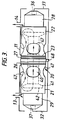
- transducers which operate at ultrasonic frequencies, are incorporated within a flow chamber assembly 20 within the duct (see also Figures 3 and 4).
- This assembly includes two cylindrical chambers 21, 22 which are affixed to a central circular support 23.
- the support also carries an inner, generally tubular member 40 coaxial with the chambers 21,22.
- O-rings 26, 27 eg of rubber which effect a seal when mounted within housing 11. This results in the chambers 21 and 22 being isolated from each other and the only passage therebetween being provided via the tube 40.
- the tube 40 includes disc-like extensions 41 at each end and the diameter of the bore of the tube increases adjacent each end in the region 42 to provide modifications to the fluid flow path as described in more detail below.
- the chambers 21,22 each include a number of circular apertures 47 around their periphery to form passageways for the fluid entry or exit.
- the fluid passes into the measuring system at inlet 13 and moves within the housing duct 11 so as to pass around the outside of chamber 21 and thence through the apertures 47 into the chamber 21.
- the fluid then continues through the chamber 21 passing over the disc-like extensions 41 and through the shaped region 42 of tube 40. After travelling down the tube 40, the fluid emerges and passes over the extension 41 and passes out through the apertures 47 in chamber 22. External of this chamber, the fluid passes through the housing and through the exit 14.
- the various passages form a labyrinth for the fluid to reduce turbulent flow in the vicinity of the tube 40.
- the shape of the tube end regions 42 and extensions 41 assist in this.
- a gas such as methane for domestic use
- the bore size of the tube 40 is chosen to be narrow is to ensure that there is sufficient speed increase to remove any stray dust particles which manage to elude the labyrinth.
- the tube bore size relative to the diameters of chamber 21 and 22 is selected to cause a speed increase which is fourfold. Too narrow a tube will cause unwanted pressure drops.
- the speed increase also helps in measuring the flow rate as described below. The exiting gas from the tube 40 will suffer a smooth transition from the fast to slow speed due to the curved tapering shape and disc extension incorporated in the tube 40.
- the gas In reverse manner at the input to the tube 40, the gas is subject to increase in flow in a controlled manner by radial contraction as it moves over disc extension 41 into the narrowing bore of the tube 40.
- transducer housing 29 Extending from the chamber 21 is a transducer housing 29 containing one of the ultrasonic transducers 37.
- the transducer as seen from Figure 2 is separated from chamber 21 by partition 45.
- transducer 37 is located at one end of a chamber 50 and the partition 45 is at the other end of the chamber 50.
- the chamber is lined with acoustic material 43 to avoid unwanted reflections at ultrasonic frequencies.
- the partition includes a circular aperture 46 in line with the transducer to allow ultrasonic signals to pass through to the tube 40.
- the aperture will be covered with gauze 51 or similar material (see Figure 4).
- the provision of chamber 50 with only a small aperture allows only generally parallel waves to pass therethrough so that some waves from the diverging beam are stopped by the partition 45.
- the location of the transducer 37 at the far end of the chamber 50 assists with this action and also reduces the risk of dust contamination of the transducer.
- the chamber partition also isolates the transducer chamber from the fluid path.
- Parallel waves are preferable, because diverging waves would tend to take a path which may be deflected by the inner wall of the tube and cause spurious speed measurements to be obtained. Hence the extremes of multimode propagation are avoided and better results are obtained.
- transducer 36 A similar arrangement is provided for transducer 36. This has a housing 28 and the transducer is located within chamber 53 at the end remote from the partition 45. This is required because the transducers are switched to alternate as transmitter and receiver, so that each transducer at certain periods will be required to provide a substantially parallel beam via the aperture 46. Acoustic lining 43 is again provided.
- the transducers are connected to the electronic circuit board via wires 32, 33 and an electrical connector 48.
- the power source for the circuits operating with the transducers is provided by battery 35.
- transducers 36,37 are spaced by a distance L.
- a transmitter/receiver block 60 employs transducer 36 to transmit a burst of signals and after these have passed through the tube 40 of Figure 3 they are received by the transducer 37 which passes the signal via the block 60 to the processor/control 61.
- the time taken for the ultrasonic signal will depend on the distance L and the speed of the gas.
- a phase reversal marker can be provided on the signal to more accurately detect the time of flight of the ultrasonic signal burst.
- the transducer operation is then reversed and the transducer 37 now becomes the transmitter and transducer 36 becomes the receiver.
- the time of travel of the burst is again computed. The difference in time measured is dependent on the gas flow rate.
- the restricted bore size of tube 40 increases relative flow rate so as to accentuate the travel time difference.
- results can be passed to display 62.
- this gas flow path will be shorter than the distance L between the transducers.
- the effective length of the moving gas column will be very close to the length of the measuring tube 40, due to the unique tube configuration with its associated entry and exit arrangements.
Landscapes
- Physics & Mathematics (AREA)
- General Physics & Mathematics (AREA)
- Fluid Mechanics (AREA)
- Engineering & Computer Science (AREA)
- Electromagnetism (AREA)
- Aviation & Aerospace Engineering (AREA)
- Multimedia (AREA)
- Acoustics & Sound (AREA)
- Measuring Volume Flow (AREA)
- Photometry And Measurement Of Optical Pulse Characteristics (AREA)
- Investigating Or Analysing Biological Materials (AREA)
- Transition And Organic Metals Composition Catalysts For Addition Polymerization (AREA)
- Acyclic And Carbocyclic Compounds In Medicinal Compositions (AREA)
- Indicating Or Recording The Presence, Absence, Or Direction Of Movement (AREA)
- Investigating Or Analyzing Materials By The Use Of Ultrasonic Waves (AREA)
Applications Claiming Priority (4)
| Application Number | Priority Date | Filing Date | Title |
|---|---|---|---|
| GB909021441A GB9021441D0 (en) | 1990-10-02 | 1990-10-02 | Measurement system |
| GB9021441 | 1990-10-02 | ||
| EP95120386A EP0708314B1 (de) | 1990-10-02 | 1991-09-09 | Messsystem |
| EP91308203A EP0479434A1 (de) | 1990-10-02 | 1991-09-09 | Ultraschalldurchflussmesser |
Related Parent Applications (1)
| Application Number | Title | Priority Date | Filing Date |
|---|---|---|---|
| EP95120386A Division EP0708314B1 (de) | 1990-10-02 | 1991-09-09 | Messsystem |
Publications (2)
| Publication Number | Publication Date |
|---|---|
| EP0907069A2 true EP0907069A2 (de) | 1999-04-07 |
| EP0907069A3 EP0907069A3 (de) | 2000-03-29 |
Family
ID=10683123
Family Applications (3)
| Application Number | Title | Priority Date | Filing Date |
|---|---|---|---|
| EP95120386A Expired - Lifetime EP0708314B1 (de) | 1990-10-02 | 1991-09-09 | Messsystem |
| EP98118465A Withdrawn EP0907069A3 (de) | 1990-10-02 | 1991-09-09 | System zum Messen der Geschwindigkeit eines Fluids |
| EP91308203A Withdrawn EP0479434A1 (de) | 1990-10-02 | 1991-09-09 | Ultraschalldurchflussmesser |
Family Applications Before (1)
| Application Number | Title | Priority Date | Filing Date |
|---|---|---|---|
| EP95120386A Expired - Lifetime EP0708314B1 (de) | 1990-10-02 | 1991-09-09 | Messsystem |
Family Applications After (1)
| Application Number | Title | Priority Date | Filing Date |
|---|---|---|---|
| EP91308203A Withdrawn EP0479434A1 (de) | 1990-10-02 | 1991-09-09 | Ultraschalldurchflussmesser |
Country Status (11)
| Country | Link |
|---|---|
| US (1) | US5243863A (de) |
| EP (3) | EP0708314B1 (de) |
| JP (1) | JPH0760160B2 (de) |
| KR (1) | KR950002058B1 (de) |
| AT (1) | ATE227420T1 (de) |
| AU (2) | AU639144B2 (de) |
| CA (1) | CA2052462C (de) |
| DE (1) | DE69133145T2 (de) |
| DK (1) | DK0708314T3 (de) |
| ES (1) | ES2186702T3 (de) |
| GB (1) | GB9021441D0 (de) |
Cited By (6)
| Publication number | Priority date | Publication date | Assignee | Title |
|---|---|---|---|---|
| WO2022032159A1 (en) * | 2020-08-07 | 2022-02-10 | Woodward, Inc. | Ultrasonic flow meter flow control |
| US11307069B2 (en) | 2020-03-06 | 2022-04-19 | Woodward, Inc. | Ultrasonic flow meter in a bypass channel coupled in parallel with a flow tube |
| US11668818B2 (en) | 2020-08-07 | 2023-06-06 | Woodward, Inc. | Ultrasonic position sensor |
| US11835374B2 (en) | 2021-03-17 | 2023-12-05 | Woodward, Inc. | Ultrasonic mass fuel flow meter |
| US12140669B2 (en) | 2020-08-07 | 2024-11-12 | Woodward, Inc. | Ratio metric position sensor and control system |
| US12399047B2 (en) | 2019-12-03 | 2025-08-26 | Woodward, Inc. | Ultrasonic mass fuel flow meter |
Families Citing this family (31)
| Publication number | Priority date | Publication date | Assignee | Title |
|---|---|---|---|---|
| US5540105A (en) * | 1992-02-13 | 1996-07-30 | Siemens Aktiengesellschaft | Funnel inlet and funnel outlet for ultrasonic gas meters |
| DE4224372C2 (de) * | 1992-07-23 | 1995-02-02 | Kromschroeder Ag G | Ultraschall-Gaszähler |
| US5247826B1 (en) * | 1992-11-12 | 1995-07-18 | Devilbiss Health Care Inc | Gas concentration and/or flow sensor |
| EP0690974A4 (de) * | 1993-03-09 | 1996-05-22 | Commw Scient Ind Res Org | Flüssigkeitsmesserkonstruktion |
| GB2276240B (en) * | 1993-03-16 | 1997-01-15 | British Gas Plc | Fluid flowmeter |
| IT1272370B (it) * | 1993-04-27 | 1997-06-23 | Nuovo Pignone Spa | Misuratore-regolatore perfezionato della portata di un fluido |
| US5458004A (en) * | 1993-09-01 | 1995-10-17 | Krohne Messtechnik Gmbh & Co. Kg. | Volume flow meter |
| US5463906A (en) * | 1994-01-24 | 1995-11-07 | Triton Technology, Inc. | Interchangeable disposable acoustic for use with an ultrasonic flowmeter, particularly during extracorporeal measurement of blood flow |
| FR2724016B1 (fr) * | 1994-08-23 | 1996-10-25 | Schlumberger Ind Sa | Dispositif de mesure ultrasonore d'une quantite volumique d'un fluide a proprietes acoustiques ameliorees |
| DE4441225C2 (de) * | 1994-11-19 | 1996-09-12 | Danfoss As | Massendurchfluß-Meßgerät |
| US5969263A (en) * | 1995-04-08 | 1999-10-19 | Schlumberger Industries, S.A. | Ultrasonic fluid counter for attenuating parasitic ultrasonic waves |
| JPH0926342A (ja) * | 1995-07-13 | 1997-01-28 | Matsushita Electric Ind Co Ltd | 超音波振動子及びこれを用いた超音波流量計 |
| US6189389B1 (en) | 1996-05-28 | 2001-02-20 | Krohne A.G. | Ultrasonic flowmeter |
| FR2776379B1 (fr) * | 1998-03-19 | 2000-04-28 | Schlumberger Ind Sa | Compteur de gaz a filtres anti-poussieres |
| JP4555669B2 (ja) * | 2004-03-02 | 2010-10-06 | 矢崎総業株式会社 | 流量計測装置 |
| GB2429061B (en) * | 2005-08-13 | 2009-04-22 | Flownetix Ltd | A method of construction for a low cost plastic ultrasonic water meter |
| DE102005046858B3 (de) * | 2005-09-29 | 2007-01-18 | Miele & Cie. Kg | Vorrichtung zum Messen der Dosiermenge von Spülzusätzen |
| JP5240763B2 (ja) * | 2008-05-23 | 2013-07-17 | 愛知時計電機株式会社 | 超音波流量計 |
| DE102010051594B4 (de) | 2010-11-16 | 2013-04-11 | Hydrometer Gmbh | Gaszähler |
| JP2012242090A (ja) * | 2011-05-16 | 2012-12-10 | Panasonic Corp | 超音波流量計 |
| JP2014157016A (ja) * | 2011-06-10 | 2014-08-28 | Panasonic Corp | ガスメータ |
| JP6060378B2 (ja) * | 2012-11-13 | 2017-01-18 | パナソニックIpマネジメント株式会社 | 流量計測装置 |
| US9996089B2 (en) | 2015-09-21 | 2018-06-12 | Blue-White Industries, Ltd. | Flow sensor devices and systems |
| JP6375519B2 (ja) * | 2016-01-12 | 2018-08-22 | パナソニックIpマネジメント株式会社 | ガスメータ |
| GB2555003B (en) * | 2016-09-23 | 2022-07-06 | Blue White Ind Ltd | Flow sensor devices and systems |
| CN109959429B (zh) * | 2017-12-26 | 2024-07-09 | 广东正扬传感科技股份有限公司 | 一种超声波探测器及探测设备 |
| GB2587844A (en) | 2019-06-07 | 2021-04-14 | Blue White Ind Ltd | Flow sensor devices and systems |
| EP3770561A1 (de) * | 2019-07-26 | 2021-01-27 | Levitronix GmbH | Ultraschall-messvorrichtung zur messung an einem strömenden fluid und ultraschall-messsystem |
| US11415442B2 (en) * | 2020-10-30 | 2022-08-16 | Honeywell International Inc. | Ultrasonic flow tube having a plurality of outer pipes surrounding a center pipe positioned between an inlet wall and an outlet wall having transducers therein |
| US12018975B2 (en) | 2021-03-11 | 2024-06-25 | Honeywell International Inc. | Ultrasound and thermal massflow in one flow channel |
| US12613119B2 (en) | 2021-08-27 | 2026-04-28 | Woodward, Inc. | Ultrasonic mass fuel flow meter |
Family Cites Families (11)
| Publication number | Priority date | Publication date | Assignee | Title |
|---|---|---|---|---|
| GB222254A (en) | 1923-07-26 | 1924-10-02 | Ernest Harold Leonard Woodward | A new or improved attachment for violins, violas, 'cellos, and other stringed instruments |
| IT1016750B (it) * | 1974-08-01 | 1977-06-20 | Fiat Spa | Dispositivo per effettuare median te ultrasuoni la misura della por tata d aria in massa nel condotto di aspirazione di motori a combu stione interna |
| DE2963483D1 (en) * | 1978-07-22 | 1982-09-30 | Robert James Redding | Fluid flow measuring apparatus |
| CH636701A5 (de) * | 1979-06-08 | 1983-06-15 | Landis & Gyr Ag | Messwertgeber zur bestimmung der durchflussmenge einer stroemenden fluessigkeit mit ultraschall. |
| US4365518A (en) * | 1981-02-23 | 1982-12-28 | Mapco, Inc. | Flow straighteners in axial flowmeters |
| US4425804A (en) * | 1981-10-29 | 1984-01-17 | The Perkin-Elmer Corp. | Ultrasonic air flow transducer for high humidity environments |
| CH655574B (de) * | 1982-03-01 | 1986-04-30 | ||
| US4506552A (en) * | 1984-01-12 | 1985-03-26 | Manning Technologies, Inc. | Coaxial flowpath apparatus |
| EP0152132A1 (de) * | 1984-01-27 | 1985-08-21 | N.V. Nederlandsche Apparatenfabriek NEDAP | Ultraschalldurchflussmengenmessgerät |
| CH670156A5 (de) * | 1986-06-17 | 1989-05-12 | Landis & Gyr Gmbh | |
| GB8813640D0 (en) * | 1988-06-09 | 1988-07-13 | Gill M J | Speed measurement device |
-
1990
- 1990-10-02 GB GB909021441A patent/GB9021441D0/en active Pending
-
1991
- 1991-09-09 DE DE69133145T patent/DE69133145T2/de not_active Expired - Fee Related
- 1991-09-09 DK DK95120386T patent/DK0708314T3/da active
- 1991-09-09 EP EP95120386A patent/EP0708314B1/de not_active Expired - Lifetime
- 1991-09-09 EP EP98118465A patent/EP0907069A3/de not_active Withdrawn
- 1991-09-09 AT AT95120386T patent/ATE227420T1/de not_active IP Right Cessation
- 1991-09-09 ES ES95120386T patent/ES2186702T3/es not_active Expired - Lifetime
- 1991-09-09 EP EP91308203A patent/EP0479434A1/de not_active Withdrawn
- 1991-09-16 US US07/760,385 patent/US5243863A/en not_active Expired - Lifetime
- 1991-09-30 CA CA002052462A patent/CA2052462C/en not_active Expired - Fee Related
- 1991-10-02 JP JP3255369A patent/JPH0760160B2/ja not_active Expired - Lifetime
- 1991-10-02 KR KR1019910017389A patent/KR950002058B1/ko not_active Expired - Fee Related
- 1991-10-02 AU AU85565/91A patent/AU639144B2/en not_active Ceased
-
1993
- 1993-05-07 AU AU38458/93A patent/AU3845893A/en not_active Abandoned
Cited By (12)
| Publication number | Priority date | Publication date | Assignee | Title |
|---|---|---|---|---|
| US12399047B2 (en) | 2019-12-03 | 2025-08-26 | Woodward, Inc. | Ultrasonic mass fuel flow meter |
| US11307069B2 (en) | 2020-03-06 | 2022-04-19 | Woodward, Inc. | Ultrasonic flow meter in a bypass channel coupled in parallel with a flow tube |
| WO2022032159A1 (en) * | 2020-08-07 | 2022-02-10 | Woodward, Inc. | Ultrasonic flow meter flow control |
| WO2022032157A1 (en) * | 2020-08-07 | 2022-02-10 | Woodward, Inc. | Ultrasonic flow meter flow control |
| US11668818B2 (en) | 2020-08-07 | 2023-06-06 | Woodward, Inc. | Ultrasonic position sensor |
| CN116368357A (zh) * | 2020-08-07 | 2023-06-30 | 伍德沃德有限公司 | 超声波流量计流控制 |
| US11885655B2 (en) | 2020-08-07 | 2024-01-30 | Woodward, Inc. | Ultrasonic flow meter having flow conditioning arrangements for flow controlling in a linear fluid conduit |
| US12140669B2 (en) | 2020-08-07 | 2024-11-12 | Woodward, Inc. | Ratio metric position sensor and control system |
| US12253396B2 (en) | 2020-08-07 | 2025-03-18 | Woodward, Inc. | Ultrasonic flow meter flow control |
| CN116368357B (zh) * | 2020-08-07 | 2026-03-13 | 伍德沃德有限公司 | 超声波流量计流控制 |
| US11835374B2 (en) | 2021-03-17 | 2023-12-05 | Woodward, Inc. | Ultrasonic mass fuel flow meter |
| US12578216B2 (en) | 2021-03-17 | 2026-03-17 | Woodward, Inc. | Ultrasonic mass fuel flow meter |
Also Published As
| Publication number | Publication date |
|---|---|
| JPH0760160B2 (ja) | 1995-06-28 |
| KR920008496A (ko) | 1992-05-28 |
| EP0708314B1 (de) | 2002-11-06 |
| DE69133145D1 (de) | 2002-12-12 |
| DK0708314T3 (da) | 2003-03-17 |
| HK1008089A1 (en) | 1999-04-30 |
| HK1015172A1 (en) | 1999-10-08 |
| DE69133145T2 (de) | 2003-07-24 |
| EP0479434A1 (de) | 1992-04-08 |
| CA2052462A1 (en) | 1992-04-03 |
| KR950002058B1 (ko) | 1995-03-10 |
| AU3845893A (en) | 1993-07-22 |
| US5243863A (en) | 1993-09-14 |
| ES2186702T3 (es) | 2003-05-16 |
| CA2052462C (en) | 1996-07-09 |
| GB9021441D0 (en) | 1990-11-14 |
| JPH04248466A (ja) | 1992-09-03 |
| EP0907069A3 (de) | 2000-03-29 |
| AU8556591A (en) | 1992-05-14 |
| ATE227420T1 (de) | 2002-11-15 |
| EP0708314A3 (de) | 1997-11-26 |
| AU639144B2 (en) | 1993-07-15 |
| EP0708314A2 (de) | 1996-04-24 |
Similar Documents
| Publication | Publication Date | Title |
|---|---|---|
| CA2052462C (en) | Measurement system | |
| AU659679B2 (en) | Measurement system | |
| US7469599B2 (en) | Flowmeter mounted on a containment | |
| KR0170815B1 (ko) | 초음파 다회선 유량계 | |
| US10809106B2 (en) | Ultrasonic flow meter configured to facilitate measurement electronics replacement | |
| US7614309B2 (en) | Cup-shaped ultrasonic transducer for a flowmeter | |
| US4397191A (en) | Liquid velocity measurement system | |
| US20100024570A1 (en) | Device for Determining or Monitoring a Medium Volume or Mass Flow Rate in a Conduit | |
| GB2248502A (en) | Acoustic fluid flowmeter | |
| SK44796A3 (en) | Ultrasonic flowmeter | |
| US3346065A (en) | Measurement apparatus for studying the physical properties of a medium | |
| HK1025380A (en) | System for measuring the speed of fluid | |
| HK1015172B (en) | Measurement system | |
| GB2155635A (en) | Monitoring fluid flow | |
| CN210166007U (zh) | 一种流量量程比较宽的气体超声波流量计 | |
| GB2209217A (en) | An ultrasonic fluid flow meter | |
| GB2209216A (en) | Ultrasonic flowmeter combined with a pressure sensor | |
| GB2209218A (en) | An ultrasonic fluid flow meter with anti-fraud means | |
| JP3500516B2 (ja) | 渦流量計 | |
| HK1012703A (en) | Measurement system | |
| JPH11351927A (ja) | 超音波装置 | |
| HK1007441B (en) | Measurement system | |
| SU371438A1 (ru) | Ультразвуковой расходомер | |
| HK1052549B (en) | Simultaneous determination of multiphase flowrates and concentrations |
Legal Events
| Date | Code | Title | Description |
|---|---|---|---|
| PUAI | Public reference made under article 153(3) epc to a published international application that has entered the european phase |
Free format text: ORIGINAL CODE: 0009012 |
|
| AC | Divisional application: reference to earlier application |
Ref document number: 708314 Country of ref document: EP |
|
| AK | Designated contracting states |
Kind code of ref document: A2 Designated state(s): AT BE DE DK ES FR GB IT NL SE |
|
| PUAL | Search report despatched |
Free format text: ORIGINAL CODE: 0009013 |
|
| AK | Designated contracting states |
Kind code of ref document: A3 Designated state(s): AT BE DE DK ES FR GB IT NL SE |
|
| 17P | Request for examination filed |
Effective date: 20000929 |
|
| RAP1 | Party data changed (applicant data changed or rights of an application transferred) |
Owner name: LATTICE INTELLECTUAL PROPERTY LIMITED |
|
| 17Q | First examination report despatched |
Effective date: 20030516 |
|
| STAA | Information on the status of an ep patent application or granted ep patent |
Free format text: STATUS: THE APPLICATION IS DEEMED TO BE WITHDRAWN |
|
| 18D | Application deemed to be withdrawn |
Effective date: 20060401 |
|
| REG | Reference to a national code |
Ref country code: HK Ref legal event code: WD Ref document number: 1025380 Country of ref document: HK |