EP0907049B1 - Schnittstellensystem zwischen einem Verbundrohr und Kupplungsstücken - Google Patents
Schnittstellensystem zwischen einem Verbundrohr und Kupplungsstücken Download PDFInfo
- Publication number
- EP0907049B1 EP0907049B1 EP98250348A EP98250348A EP0907049B1 EP 0907049 B1 EP0907049 B1 EP 0907049B1 EP 98250348 A EP98250348 A EP 98250348A EP 98250348 A EP98250348 A EP 98250348A EP 0907049 B1 EP0907049 B1 EP 0907049B1
- Authority
- EP
- European Patent Office
- Prior art keywords
- traplock
- fitting
- composite tube
- grooves
- filaments
- Prior art date
- Legal status (The legal status is an assumption and is not a legal conclusion. Google has not performed a legal analysis and makes no representation as to the accuracy of the status listed.)
- Expired - Lifetime
Links
- 239000002131 composite material Substances 0.000 title claims abstract description 73
- 230000002787 reinforcement Effects 0.000 description 28
- 239000000835 fiber Substances 0.000 description 24
- 239000000463 material Substances 0.000 description 12
- 238000013461 design Methods 0.000 description 8
- 238000000034 method Methods 0.000 description 5
- 229920005989 resin Polymers 0.000 description 5
- 239000011347 resin Substances 0.000 description 5
- 239000000853 adhesive Substances 0.000 description 4
- 230000001070 adhesive effect Effects 0.000 description 4
- 238000004519 manufacturing process Methods 0.000 description 4
- 239000011324 bead Substances 0.000 description 3
- 238000009954 braiding Methods 0.000 description 3
- 238000007906 compression Methods 0.000 description 3
- 230000006835 compression Effects 0.000 description 3
- 238000009730 filament winding Methods 0.000 description 3
- 239000002184 metal Substances 0.000 description 3
- 229910052751 metal Inorganic materials 0.000 description 3
- 238000004513 sizing Methods 0.000 description 3
- 229920001169 thermoplastic Polymers 0.000 description 3
- 229920001187 thermosetting polymer Polymers 0.000 description 3
- 239000004416 thermosoftening plastic Substances 0.000 description 3
- 238000013459 approach Methods 0.000 description 2
- 238000005336 cracking Methods 0.000 description 2
- 238000006073 displacement reaction Methods 0.000 description 2
- 238000009826 distribution Methods 0.000 description 2
- 229920001971 elastomer Polymers 0.000 description 2
- 239000012530 fluid Substances 0.000 description 2
- 239000007789 gas Substances 0.000 description 2
- 238000002347 injection Methods 0.000 description 2
- 239000007924 injection Substances 0.000 description 2
- 239000007788 liquid Substances 0.000 description 2
- 238000011068 loading method Methods 0.000 description 2
- 229920001778 nylon Polymers 0.000 description 2
- 230000003014 reinforcing effect Effects 0.000 description 2
- 238000007789 sealing Methods 0.000 description 2
- OKTJSMMVPCPJKN-UHFFFAOYSA-N Carbon Chemical compound [C] OKTJSMMVPCPJKN-UHFFFAOYSA-N 0.000 description 1
- 239000004593 Epoxy Substances 0.000 description 1
- 239000004677 Nylon Substances 0.000 description 1
- 239000004952 Polyamide Substances 0.000 description 1
- 229910000831 Steel Inorganic materials 0.000 description 1
- 239000004760 aramid Substances 0.000 description 1
- 229920003235 aromatic polyamide Polymers 0.000 description 1
- 230000004888 barrier function Effects 0.000 description 1
- 229910052799 carbon Inorganic materials 0.000 description 1
- 230000000295 complement effect Effects 0.000 description 1
- 239000012141 concentrate Substances 0.000 description 1
- 238000007596 consolidation process Methods 0.000 description 1
- 230000008878 coupling Effects 0.000 description 1
- 238000010168 coupling process Methods 0.000 description 1
- 238000005859 coupling reaction Methods 0.000 description 1
- 230000007423 decrease Effects 0.000 description 1
- 238000011161 development Methods 0.000 description 1
- 239000000806 elastomer Substances 0.000 description 1
- 230000007613 environmental effect Effects 0.000 description 1
- 125000003700 epoxy group Chemical group 0.000 description 1
- 230000001747 exhibiting effect Effects 0.000 description 1
- 239000002657 fibrous material Substances 0.000 description 1
- 238000009472 formulation Methods 0.000 description 1
- 230000004927 fusion Effects 0.000 description 1
- 210000004907 gland Anatomy 0.000 description 1
- 239000011521 glass Substances 0.000 description 1
- 229920001903 high density polyethylene Polymers 0.000 description 1
- 239000004700 high-density polyethylene Substances 0.000 description 1
- 238000009434 installation Methods 0.000 description 1
- 230000013011 mating Effects 0.000 description 1
- 239000007769 metal material Substances 0.000 description 1
- 150000002739 metals Chemical class 0.000 description 1
- 238000013508 migration Methods 0.000 description 1
- 230000005012 migration Effects 0.000 description 1
- 239000000203 mixture Substances 0.000 description 1
- 229920002647 polyamide Polymers 0.000 description 1
- 229920000647 polyepoxide Polymers 0.000 description 1
- 229920000728 polyester Polymers 0.000 description 1
- 229920000642 polymer Polymers 0.000 description 1
- 235000013824 polyphenols Nutrition 0.000 description 1
- 230000008569 process Effects 0.000 description 1
- 239000011253 protective coating Substances 0.000 description 1
- 230000001681 protective effect Effects 0.000 description 1
- 230000000717 retained effect Effects 0.000 description 1
- 238000000926 separation method Methods 0.000 description 1
- 238000010008 shearing Methods 0.000 description 1
- 239000000243 solution Substances 0.000 description 1
- 239000010959 steel Substances 0.000 description 1
- 239000012815 thermoplastic material Substances 0.000 description 1
- 229920005992 thermoplastic resin Polymers 0.000 description 1
- 229920001567 vinyl ester resin Polymers 0.000 description 1
- 125000000391 vinyl group Chemical group [H]C([*])=C([H])[H] 0.000 description 1
- 239000003039 volatile agent Substances 0.000 description 1
- 238000004804 winding Methods 0.000 description 1
Images

Classifications
-
- F—MECHANICAL ENGINEERING; LIGHTING; HEATING; WEAPONS; BLASTING
- F16—ENGINEERING ELEMENTS AND UNITS; GENERAL MEASURES FOR PRODUCING AND MAINTAINING EFFECTIVE FUNCTIONING OF MACHINES OR INSTALLATIONS; THERMAL INSULATION IN GENERAL
- F16L—PIPES; JOINTS OR FITTINGS FOR PIPES; SUPPORTS FOR PIPES, CABLES OR PROTECTIVE TUBING; MEANS FOR THERMAL INSULATION IN GENERAL
- F16L9/00—Rigid pipes
- F16L9/12—Rigid pipes of plastics with or without reinforcement
-
- F—MECHANICAL ENGINEERING; LIGHTING; HEATING; WEAPONS; BLASTING
- F16—ENGINEERING ELEMENTS AND UNITS; GENERAL MEASURES FOR PRODUCING AND MAINTAINING EFFECTIVE FUNCTIONING OF MACHINES OR INSTALLATIONS; THERMAL INSULATION IN GENERAL
- F16L—PIPES; JOINTS OR FITTINGS FOR PIPES; SUPPORTS FOR PIPES, CABLES OR PROTECTIVE TUBING; MEANS FOR THERMAL INSULATION IN GENERAL
- F16L47/00—Connecting arrangements or other fittings specially adapted to be made of plastics or to be used with pipes made of plastics
- F16L47/02—Welded joints; Adhesive joints
Definitions
- the present invention generally relates to the art of filament composite tubes and, particularly, to various features at the interface between a filament composite tube and a rigid end fitting.
- Filament composite tubes typically include aligned reinforcement fibers in combination with thermosetting or thermoplastic resin.
- Such tubes are manufactured by the application of resin-impregnated reinforcement fibers or rovings to an internal cylindrical mandrel.
- the rovings are applied under controlled tension in precise orientations and thicknesses to produce a tube wall with desired properties. This can be accomplished by filament winding, whereby the mandrel is rotated about its centerline and the roving is applied along the mandrel by a carriage assembly.
- Braiding can also be used, whereby the internal mandrel is passed through roving delivery heads which orbit around the mandrel. Numerous hybrid processes exist which combine features of filament winding and braiding.
- the reinforcement fibers may include axial reinforcements or circumferential (hoop) reinforcements.
- the axial reinforcements are sized to provide the tube with the axial strength and/or stiffness required for a particular application.
- the circumferential or hoop reinforcements are sized to provide the tube with the circumferential strength and/or stiffness required for a particular application.
- the resin stabilizes and transfers load between the reinforcements fibers and protects the fibers from environmental attack.
- Thermosetting resins such as epoxies, phenolics, vinyl esters and polyesters are most commonly used. Less commonly used are thermoplastics such as nylons.
- the thermosetting resins are used most commonly because they can be applied to the roving in liquid form, which aids in the removal of entrapped air or volatiles.
- the resin is solidified by the addition of heat energy, resulting in a rigid fiber-reinforced structure. The internal mandrel then is withdrawn, typically to be used again.
- an elastomeric or thermoplastic liner typically is used inside the tube to prevent migration of the contained fluids through the composite wall.
- Composite tubes as described above are used in a variety of product applications, including oil and gas production and development applications, including tubing, casing and risers. Such tubes are also representative of a pressure vessel with a large port opening relative to its cylinder diameter, a common configuration for rocket motor cases. They also are used as a structural composite strut or link applicable to lightweight truss or frame systems. In these applications, a joint is required to react primarily to axial loadings, resulting from applied axial tension and/or internal pressure. Joints are required between tube lengths in order to afford good service in these applications.
- the joints typically are provided by end fittings at wound-in interfaces between the tubes and the fittings.
- the end fittings are generally hollow, rigid structures typically fabricated of metallic or like material.
- the wound-in interface between a filament composite tube and a rigid interior end fitting often includes one or more "traplock" grooves in the exterior of the fitting and into which the filament or reinforcements of the composite tube are wound and/or compacted.
- the axial load is transferred between the composite tube and the end fitting through bearing on the inboard or load-carrying face of the traplock groove.
- the surface area of the load-carrying face is one of the parameters determining the strength of the joint or interface.
- the bearing area can be increased by increasing the height of the load-carrying face.
- the bearing stress which the composite material can support is relatively low (30 to 50 ksi).
- the diametral envelope required by a single traplock groove can become quite large as the height of the load-carrying face is increased.
- the diametral requirements of the joint can be reduced by the use of multiple traplock grooves, but there is no efficient method known for determining the precise number of grooves necessary and such determinations typically are arbitrary.
- traplock grooves do not necessarily result in improved joint performance. It is desirable that all traplock grooves be equally reiriforced and all traplock grooves carry an equal share of the load. If the interface is not designed properly, the load may not be distributed equally between the multiple traplock grooves. It is possible to load any one traplock groove to failure before other traplock grooves carry significant load.
- Still further problems are encountered in establishing and maintaining a pressure-tight seal between the composite tube and the end fitting. This is particularly true if the composite tube has an interior liner.
- a pressure-actuated (O-ring) seal for instance, is not feasible because the fitting is encapsulated in the end of the composite tube during its fabrication.
- the flow of the resin prior to its consolidation precludes the forming in place of sealing features such as grooves or glands.
- Reliance on an adhesive bond between the end fitting and the tube liner is not reliable due to the differential movement in the axial direction that is inherent in traplock system operation. As the fitting moves outboard under load, the liner material and adhesive typically cannot accommodate this differential movement without cracking, tearing or unbonding.
- the present invention is directed to solving the above myriad of problems by providing features at the interface between a filament composite tube and a rigid end fitting to enhance the properties and performance of the components at the interface.
- US-A-2,854,030 patent discloses a hose/fitting interface in which the fitting has two spaced-apart external beads.
- the external beads appear to be identical in shape, and therefore their bearing surfaces are identical.
- the '030 patent fails to disclose or suggest that the bearing faces of the external beads have different angles.
- US-A-3,799,587 discloses a coupling device for a flexible pipe to a rigid tubular element.
- Tubular element has a jagged outline, as shown in FIG. 2B, having a number of "jags" protruding from its surface. The jags all appear to have identical shapes.
- the '587 patent fails to disclose or suggest that the bearing faces of the jags 12 have different angles.
- GB-A-1 345 688 patent discloses a hose/fitting interface in which the fitting has a number of circumferential steel rings attached thereto. A hose lining and reinforcing layers are positioned over the rings, and wire windings are applied to the hose lining and reinforcing layers between the rings.
- the rings are all shown having identical rectangular cross-sections. As such, the '688 patent also fails to disclose or suggest that the bearing faces of the rings have different angles.
- An object, therefore, of the invention is to provide a new and improved interface system between a filament composite tube and an end fitting.
- Another object of the invention is to provide a new and improved traplock system between an end of a filament composite tube and a generally hollow, rigid interior end fitting.
- a further object of the invention is to provide a new and improved sealing system between a filament composite tube and an end fitting, including a composite tube with an elastomeric liner.
- the invention relates to traplock system as claimed in claim 1.
- the end fitting has an inboard end and an outboard end with a plurality of circumferential exterior grooves defining a plurality of traplocks spaced axially between the ends.
- the wall thicknesses between the bases of the traplock grooves and the inside of the generally hollow fitting are different for at least some of the traplock grooves.
- the composite tube has filaments disposed in the traplock grooves of the fitting to lock the tube to the fitting.
- the wall thicknesses at the bases of the traplock grooves increase from the traplock groove nearest the inboard end of the fitting to the traplock groove nearest the outboard end of the fitting. As disclosed herein, the wall thicknesses increase at a uniform rate.
- the traplock grooves have angled bearing faces which-face toward the outboard end of the fitting and against which the filaments of the composite tube bear.
- the invention contemplates that the angles of the bearing faces be different for at least some of the traplock grooves.
- the angles increase from the traplock groove nearest the inboard end of the fitting to the traplock groove nearest the outboard end of the fitting. As disclosed herein, the angles increase at a uniform rate.
- an elastomeric release layer is disposed between the innermost filaments of the composite tube and the outside of the end fitting.
- the release layer is unbonded to the fitting.
- the filaments of the composite tube are compacted into the traplock grooves over the release layer.
- the filaments include axially extending filaments compacted into the groove by circumferentially extending filaments.
- the seal is generally Y-shaped in cross-section to define a pair of diverging arms embracing the inside and the outside of the fitting at the inboard end thereof.
- the composite tube has an interior elastomeric liner, and the Y-shaped seal defines a leg extending from the diverging arms, with the leg being unitary with the liner.
- the diverging arms of the seal and the end fitting may be provided with complementary interengaging tongue and groove locking means.
- Figure 1 shows the general configuration of a composite tube/end fitting interface, generally designated 10, with which the features of the invention are applicable.
- the interface includes a filament composite tube, generally designated 12, and a generally hollow, rigid interior end fitting, generally designated 14.
- the end fitting has an inboard end 14a and an outboard end 14b.
- the end fitting is fabricated of such rigid materials as metal.
- the inset of Figure 1 shows that filament composite tube 12 includes a plurality of layers of axial reinforcement fibers 16 sandwiched between a plurality of layers of circumferential reinforcement fibers or hoops 18.
- An elastomeric liner 20 is disposed on the inside of the composite tube.
- the reinforcement fibers are compacted into a plurality of traplock grooves 22 near inboard end 14a of the fitting, with the circumferential reinforcement fibers 18 compacting the axial reinforcement fibers into the traplock grooves.
- a seal is disposed between composite tube 12 and end fitting 14 at inboard end 14a of the fitting.
- FIG. 2 illustrates the simplest and most common embodiment of a traplock joint or interface.
- Fitting 14 is provided with a single conical surface 26. The diameter of the conical surface decreases toward the outboard end 14b of the fitting.
- axial reinforcement fibers 16 are placed over conical surface 26.
- the outboard end of the layer is compacted and captured against the conical surface by over-wrapping circumferential reinforcement fiber layers 18, forming what is referred to as a trap 28.
- a final layer 18a of circumferential or hoop fibers are provided as a protective coating about the exterior of the composite tube.
- Inboard axial forces on composite tube 12 and, therefore, the traplock joint are represented by arrows "A”.
- Outboard axial forces on end fitting 14 and, therefore, the traplock joint are represented by arrows "B".
- the features of the present invention revolve around configuring multiple traplock geometries resulting in an equal sharing of load between the multiple traplocks.
- the invention compensates for significant differences in the sectional properties of the metallic fitting and the composite tube.
- the detailed fitting geometries are determined based on finite element analysis of the joint, resulting in an equal distribution of load between the multiple traplocks.
- the total wall thickness of the traplock joint configured with a single traplock face as shown in Figure 2 generally is the sum of the fitting wall thickness under the traplock, the depth of the traplock, and the thickness of axial and/or circumferentiai reinforcement fibers outside the traplock. If this total wall thickness is compatible with the diametral envelope restrictions for the particular application of the tube/fitting interface, then a single traplock configuration as shown in Figure 2 and described above is appropriate.
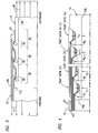
- FIG. 3 illustrates how an equivalent bearing area can be achieved within a smaller wall thickness, in this case by using three traplocks.
- the invention contemplates a particular sizing of the wall thickness of fitting 14 at the bottom of each traplock, based on the strength capabilities of the end fitting material.
- the wall thickness of the fitting at the bottom of each traplock should be the minimum required for strength requirements to minimize the stiffness mismatch between the fitting and the tube.
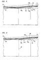
- Figure 4 shows a multiple traplock design with n traplocks. It can be seen that the end fitting wall under Traplock (n), thickness t n , must be sized to carry the total axial load. However, the thickness of the end fitting wall under Traplock (n-l), thickness t n-1 , may be sized to carry only that portion of the axial load transferred across traplock faces inboard of its location. The end fitting wall under Traplock (1), thickness t 1 may be sized to carrying only that portion of the axial load transferred across the inboard traplock face.
- the wall thickness must be sized taking all loads into account.
- the end fitting wall thickness under each traplock may be sized thicker than required from strength, again to minimize the stiffness mismatch between end fitting and composite.
- the invention contemplates a multi-traplock design in which the bearing faces of the traplocks have different angles to achieve a stress equivalence between the traplocks. More particularly, once the gross geometries of the multiple traplock interface or joint have been determined based on strength and geornetric requirements as described in detail above leading up to a decision whether or not a single traplock (Fig. 2) configuration is appropriate, an iterative approach is used to achieve a design with equal load sharing between traplocks according to the concepts of the invention.
- a unique feature of the invention is the use of different angles on the load-bearing faces of the individual traplocks to influence load sharing between traplocks.
- the angle of the load-bearing face of a traplock determines the relationship between load transferred across the face and the relative axial displacement of the end fitting and the filament composite at the traplock. Therefore, the use of different angles on the multiple traplocks influences the relative displacement between traplocks and, consequently, the load sharing between the traplocks.
- the following describes a method by which an optimized combination of angles for the load-bearing faces can be determined.
- Figure 4 illustrates the concept for a traplock joint with 'n' traplocks.
- the overall joint geometry including the amount of axial and circumferential material to be placed in each traplock, is determined based on strength and geometric constraints.
- the extreme inboard traplock is here referred to as Traplock (1), and ⁇ 1 is the angle on its load-bearing face.
- the extreme outboard traplock is here referred to as Traplock (n), and ⁇ n is the angle on its load-bearing face.
- a value for ⁇ n is chosen, typically between 30° and 60°.
- ⁇ 1 , ⁇ 2 , ..., ⁇ n-2 , ⁇ n-1 are given a value of 0°.
- the behavior of the structure under load is analyzed using the finite element method (or any other method which takes into account the relative stiffness of the fitting and composite in the axial and circumferential directions).
- the load share between Traplock (n) and Traplock (n-1) is evaluated by comparing peak bearing stresses in the composite material in the traps.
- Another embodiment of the present invention generally, comprises a seal configuration capable of compensating for a differential movement between end fitting 14 and composite tube 12 without losing its integrity.
- the seal is in the form of a Y-shaped member, generally designated 24 in Figure 5.
- the Y-shaped seal is a thermoplastic member and the material must be capable of large deformations without cracking or tearing. The use of materials exhibiting elongation at failure in excess of 200% is essential to successful seal operation.
- the Y-shaped configuration of the seal defines a pair of diverging arms 24a and 24b, along with a leg 24c. This geometry is configured for elastomeric materials where a high quality adhesive bond can be produced between the seal material and the end fitting.
- the inboard end 14a of the fitting is machined with tapered lands 30 and 32 respectively on the inside diameter and the outside diameter of the fitting. These lands are prepared for bonding so that when the elastomeric seal is compression molded or injection molded onto the fitting, an adhesive bond is created which prevents separation of the seal from the fitting.
- the fitting, with the seal installed is mounted on the mandrel that forms the inside surface of composite tube 12.
- the uncured elastomeric liner 20 is applied to the entire surface of the mandrel and extends some distance outboard on the exterior surface of the seal.
- the composite tube then is created over the mandrel/liner by filament winding and/or braiding.
- the liner is bonded to the seal and a pressure-tight barrier is created to prevent the permeation of contained fluids through the composite wall.
- Figure 6 shows a Y-shaped seal 24A that allows the use of seal materials which cannot be reliably bonded to fitting 14, such as high density polyethylene and polyamide (nylon).
- fitting 14 such as high density polyethylene and polyamide (nylon).
- the inboard end 14A of fitting 14 is machined with locking grooves 34 and 36 respectively on the inside diameter and outside diameter of the fitting.
- the locking grooves are wider than the mouths of the grooves, or the grooves may be dovetailed in cross-section, to provide secure locking of mating ribs extending into the grooves from diverging arms 24a and 24b of the seal.
- the seal is injection molded onto the fitting, the thermoplastic material flows into the locking grooves and is mechanically retained in place.
- the seal/fitting assembly Prior to installation onto a mandrel, the seal/fitting assembly is fusion welded, as at 38, to an extruded liner 20, creating a pressure tight welded liner assembly. The welded liner assembly then is slid over the mandrel and the composite tube is fabricated over the assembly.
- a further embodiment of the invention comprises the provision of an elastomeric release layer 40 between the innermost filaments of composite tube 12 and the outside of end fitting 14.
- the release layer is unbonded to the fitting.
- This release layer further compensates for differential movement between the fitting and the composite tube inherent to traplock operation.
- the release layer may be fabricated of such materials as rubber or the like. The release layer ensures that load is concentrated on the compression side or load-bearing surfaces 26 of the traplocks.
Landscapes
- Engineering & Computer Science (AREA)
- General Engineering & Computer Science (AREA)
- Mechanical Engineering (AREA)
- Rigid Pipes And Flexible Pipes (AREA)
- Lining Or Joining Of Plastics Or The Like (AREA)
- Earth Drilling (AREA)
- Joints Allowing Movement (AREA)
- Supports For Pipes And Cables (AREA)
- Separation Using Semi-Permeable Membranes (AREA)
- Electric Cable Installation (AREA)
- Paper (AREA)
- Quick-Acting Or Multi-Walled Pipe Joints (AREA)
Claims (12)
- Verriegelungssystem zwischen einem Ende eines Faserverbundrohres (12) und einem im allgemeinen hohlen, starren Innenendfitting (14), wobei:dadurch gekennzeichnet, daß die Winkel der Halteflächen (26) für zumindest einige der Verriegelungsnuten (22) unterschiedlich sind.der Fitting (14) ein innenliegendes Ende (14a) und ein außenliegendes Ende (14b) mit einer Anzahl von äußeren Umfangsnuten (22) hat, die eine Anzahl von Verriegelungen (28) bilden, die zwischen den Enden axial beabstandet sind, wobei die Verriegelungsnuten (22) abgewinkelte Halteflächen (26) haben, die in Richtung auf das außenliegende Ende (14b) des Fittings (14) geneigt sind und gegen die die Fasern (16) des Verbundrohrs (12) drücken;wobei das Faserverbundrohr (12) Fasern (18) aufweist, die in den Verriegelungsnuten (22) des Fittings liegen, um das Faserverbundrohr (12) mit dem Fitting (14) zu verriegeln; und
- Verriegelungssystem nach Anspruch 1, wobei die Winkel der Halteflächen (26) von der Verriegelungsnut (22), die am nächsten zu dem innenliegenden Ende (14a) des Fittings (14) liegt, zu der Verriegelungsnut (22), die am nächsten zum außenliegenden Ende (14b) des Fittings (14) liegt, zunehmen.
- Verriegelungssystem nach Anspruch 2, wobei die Winkel der Halteflächen (26) der Verriegelungsnuten (22) gleichmäßig zunehmen.
- Verriegelungssystem nach Anspruch 1, mit einer elastomeren Freigabeschicht (40) zwischen den am weitesten innen liegenden Fasern des Verbundrohrs (12) und der Außenseite des Endfittings (14), wobei die Freigabeschicht (40) nicht mit dem Fitting (14) verbunden ist.
- Verriegelungssystem nach Anspruch 1, wobei die Fasern des Verbundrohrs (12) in die Verriegelungsnuten (22) verdichtet eingebracht sind.
- Verriegelungssystem nach Anspruch 5, wobei die Fasern (16) axial verlaufende Fasern umfassen, die in die Verriegelungsnuten (22) durch sich in Umfangsrichtung erstreckende Fasern (18) eingedrückt sind.
- Verriegelungssystem nach Anspruch 1, mit einer flexiblen Dichtung (24) zwischen dem innenliegenden Ende (14a) des Fittings (14) und der Innenseite des Faserverbundrohrs (12).
- Verriegelungssystem nach Anspruch 7, wobei die Dichtung (24) im Querschnitt im allgemeinen Y-förmig ist, um ein Paar divergierender Arme (24a) und (25b) zu bilden, die die Innenseite und die Außenseite des Fittings (14) an dessen innenliegendem Ende (14a) umfassen.
- Verriegelungssystem nach Anspruch 8, wobei das Verbundrohr (12) eine innere elastomere Auskleidung (20) hat, und wobei die Y-förmige Dichtung (24) einen Schenkel (24c) bildet, der sich von den divergierenden Armen (24a) und (24b) erstreckt, wobei der Schenkel (24c) Teil der Auskleidung (20) ist.
- Verriegelungssystem nach Anspruch 7, wobei das Verbundrohr (12) eine innere elastomere Auskleidung (20) hat, die Teil der flexiblen Dichtung (24) ist.
- Verriegelungssystem nach Anspruch 1, wobei die Wandstärke zwischen der Basis der Verriegelungsnuten (22) und der Innenseite des im allgemein hohlen Fittings (14) von der Verriegelungsnut (22), die am nächsten zum Innenende (14a) des Fittings (14) liegt, zu der Verriegelungsnut (22) hin, die am nächsten zum Außenende (14b) des Fittings (14) liegt, zunimmt.
- Verriegelungssystem nach Anspruch 11, wobei die Wandstärke gleichmäßig zunimmt.
Applications Claiming Priority (2)
| Application Number | Priority Date | Filing Date | Title |
|---|---|---|---|
| US942414 | 1997-10-01 | ||
| US08/942,414 US6042152A (en) | 1997-10-01 | 1997-10-01 | Interface system between composite tubing and end fittings |
Publications (3)
| Publication Number | Publication Date |
|---|---|
| EP0907049A2 EP0907049A2 (de) | 1999-04-07 |
| EP0907049A3 EP0907049A3 (de) | 2001-05-16 |
| EP0907049B1 true EP0907049B1 (de) | 2005-11-16 |
Family
ID=25478034
Family Applications (1)
| Application Number | Title | Priority Date | Filing Date |
|---|---|---|---|
| EP98250348A Expired - Lifetime EP0907049B1 (de) | 1997-10-01 | 1998-09-30 | Schnittstellensystem zwischen einem Verbundrohr und Kupplungsstücken |
Country Status (10)
| Country | Link |
|---|---|
| US (1) | US6042152A (de) |
| EP (1) | EP0907049B1 (de) |
| AT (1) | ATE310199T1 (de) |
| AU (1) | AU753881B2 (de) |
| BR (1) | BR9803952A (de) |
| CA (1) | CA2249045C (de) |
| DE (1) | DE69832350T2 (de) |
| ID (1) | ID21092A (de) |
| NO (1) | NO329230B1 (de) |
| SG (1) | SG72869A1 (de) |
Cited By (1)
| Publication number | Priority date | Publication date | Assignee | Title |
|---|---|---|---|---|
| US9068476B2 (en) | 2011-12-22 | 2015-06-30 | Pratt & Whitney Canada Corp. | Hybrid metal/composite link rod for turbofan gas turbine engine |
Families Citing this family (25)
| Publication number | Priority date | Publication date | Assignee | Title |
|---|---|---|---|---|
| US6676169B1 (en) | 1999-09-22 | 2004-01-13 | Hydril Company L.P. | Connection for composite tubing |
| US6863279B2 (en) | 2001-12-05 | 2005-03-08 | Conoco Investments Norge Ad | Redundant seal design for composite risers with metal liners |
| US6719058B2 (en) * | 2001-12-05 | 2004-04-13 | Deepwater Composites As | Multiple seal design for composite risers and tubing for offshore applications |
| US7090006B2 (en) | 2002-11-05 | 2006-08-15 | Conocophillips Company | Replaceable liner for metal lined composite risers in offshore applications |
| US20040086341A1 (en) * | 2002-11-05 | 2004-05-06 | Conoco Inc. | Metal lined composite risers in offshore applications |
| US20040145180A1 (en) * | 2003-01-15 | 2004-07-29 | Mayer Martin G. | Reinforced composite boom pipe with bonded sleeves |
| ES2277272T3 (es) * | 2003-05-12 | 2007-07-01 | Putzmeister Inc. | Tuberia de material compuesto con filamentos enrollados montada en grua. |
| FR2857690B1 (fr) * | 2003-07-15 | 2005-08-26 | Inst Francais Du Petrole | Systeme de forage en mer comprenant une colonne montante haute pression |
| US20050100414A1 (en) * | 2003-11-07 | 2005-05-12 | Conocophillips Company | Composite riser with integrity monitoring apparatus and method |
| NO322237B1 (no) * | 2004-09-27 | 2006-09-04 | Aker Subsea As | Komposittrør og fremgangsmåte for fremstilling av et komposittrør |
| US8414724B2 (en) * | 2006-12-02 | 2013-04-09 | The Boeing Company | Composite tube having cobonded end fittings and method of making same |
| AT505512B1 (de) * | 2007-07-03 | 2009-09-15 | Teufelberger Gmbh | Anordnung zum verbinden eines länglichen elements mit einer weiteren komponente |
| NZ561410A (en) * | 2007-09-11 | 2010-04-30 | Parker Hannifin Gmbh | End-fittings for composite tubes, method for joining fittings to the ends of composite tubes and composite tubes incorporating end-fittings |
| GB2473007B (en) | 2009-08-26 | 2012-11-21 | Messier Dowty Ltd | Apparatus comprising an end fitting connected to a body |
| FR2961427B1 (fr) | 2010-06-22 | 2012-06-15 | Inst Francais Du Petrole | Procede de frettage pour renforcer un tube a la tenue axiale et a la tenue a la pression interne |
| FR2984449B1 (fr) * | 2011-12-20 | 2014-10-10 | IFP Energies Nouvelles | Element de conduite en tube frette avec des elements de transition |
| US10167075B2 (en) * | 2013-06-25 | 2019-01-01 | The Boeing Company | Joint assembly and method of forming thereof |
| US9470350B2 (en) | 2013-07-23 | 2016-10-18 | Spencer Composites Corporation | Metal-to-composite interfaces |
| US9441374B2 (en) * | 2014-04-08 | 2016-09-13 | Goodrich Corporation | Struts and methods utilizing a compression collar |
| CN104832487A (zh) * | 2014-09-18 | 2015-08-12 | 北汽福田汽车股份有限公司 | 驱动缸的缸筒过渡连接头及具有其的驱动缸 |
| US11041585B2 (en) * | 2016-06-08 | 2021-06-22 | Avtechtyee Inc. | Fitting collar and tube-fitting assemblies incorporating fitting collars |
| US10532518B2 (en) | 2016-10-05 | 2020-01-14 | Goodrich Corporation | Hybrid metallic/composite joint with enhanced performance |
| US11333105B1 (en) * | 2018-04-27 | 2022-05-17 | United States Of America As Represented By The Administrator Of Nasa | Thrust chamber liner and fabrication method therefor |
| CN112628479B (zh) * | 2020-12-21 | 2023-06-13 | 赵培翔 | 一种宽幅纤维网增强塑料复合管材 |
| NL2027502B1 (en) * | 2021-02-05 | 2022-09-06 | Stichting Administratiekantoor Cra | Tubing connector for composite tubing, composite tubing, and methods of using the same |
Family Cites Families (25)
| Publication number | Priority date | Publication date | Assignee | Title |
|---|---|---|---|---|
| US590258A (en) * | 1897-09-21 | Connecting hose to nipples | ||
| US237324A (en) * | 1881-02-01 | reynolds | ||
| US768188A (en) * | 1903-12-18 | 1904-08-23 | John J Mcintyre | Hose-binder. |
| US1980466A (en) * | 1932-02-23 | 1934-11-13 | Jose M Angeja | Hose connection |
| US2661225A (en) * | 1950-01-14 | 1953-12-01 | Gilbert T Lyon | Hose clamp fitting connection |
| US2750210A (en) * | 1952-12-17 | 1956-06-12 | Trogdon Olin | Hose coupling with braided gripping sleeve |
| US2854030A (en) * | 1956-09-13 | 1958-09-30 | Schulthess Ernest | Oil hose |
| US2973975A (en) * | 1957-10-31 | 1961-03-07 | Titeflex Inc | Reusable fitting for braid-covered hose |
| US3165338A (en) * | 1961-08-03 | 1965-01-12 | Moore & Co Samuel | Hose coupling |
| US3119415A (en) * | 1962-03-09 | 1964-01-28 | Porter Co Inc H K | Buoyant hose |
| US3381715A (en) * | 1964-02-25 | 1968-05-07 | Rock Island Oil & Refining Co | Glass-reinforced threads with silica powder disposed therein |
| US3347571A (en) * | 1965-08-30 | 1967-10-17 | Stratoflex Inc | Hose fitting |
| US3423109A (en) * | 1966-03-30 | 1969-01-21 | Stratoflex Inc | Hose fitting |
| US3495627A (en) * | 1968-09-30 | 1970-02-17 | Koch Ind Inc | Method of forming fiber glass pipe with integral joint thread |
| US3799587A (en) * | 1969-04-03 | 1974-03-26 | Inst Francais Du Petrole | Couplings of reduced size and capable of transmitting high mechanical stresses between an armoured flexible member and a rigid element |
| GB1354688A (en) * | 1970-05-21 | 1974-06-05 | Dunlop Holdings Ltd | Flexible hose with tapered bore |
| GB1444257A (en) * | 1973-07-06 | 1976-07-28 | Dunlop Ltd | Fastening assemblies |
| DE2951629C2 (de) * | 1979-12-21 | 1985-03-14 | Felten & Guilleaume Energietechnik GmbH, 5000 Köln | Antriebswelle aus faserverstärktem Kunststoff, mit verlorenem Dorn und festgewickelten Endstücken |
| US4385644A (en) * | 1982-01-11 | 1983-05-31 | Plastonics International Inc. | Composite laminate joint structure and method and apparatus for making same |
| US4569541A (en) * | 1983-09-08 | 1986-02-11 | The Goodyear Tire & Rubber Company | Heavy duty hose coupling and method for manufacture of hose-coupling combination |
| SU1528995A1 (ru) * | 1987-07-20 | 1989-12-15 | Ю. И. Гуркин | Разъемное соединение трубопроводов |
| US5061826A (en) * | 1990-07-17 | 1991-10-29 | G & H Technology, Inc. | High strength flexible housing |
| FR2675563B1 (fr) * | 1991-04-22 | 1993-08-27 | Aerospatiale | Procede d'assemblage mecanique d'un tube en materiau composite et d'une piece metallique et assemblage ainsi realise. |
| FR2683260B1 (fr) * | 1991-11-05 | 1995-10-20 | Aerospatiale | Tube en materiau composite pour forage et/ou transport de produits liquides ou gazeux, en particulier pour l'exploitation petroliere en mer et procede de fabrication d'un tel tube. |
| US5332049A (en) * | 1992-09-29 | 1994-07-26 | Brunswick Corporation | Composite drill pipe |
-
1997
- 1997-10-01 US US08/942,414 patent/US6042152A/en not_active Expired - Lifetime
-
1998
- 1998-09-25 NO NO19984461A patent/NO329230B1/no not_active IP Right Cessation
- 1998-09-29 CA CA002249045A patent/CA2249045C/en not_active Expired - Lifetime
- 1998-09-30 AT AT98250348T patent/ATE310199T1/de not_active IP Right Cessation
- 1998-09-30 SG SG1998003947A patent/SG72869A1/en unknown
- 1998-09-30 DE DE69832350T patent/DE69832350T2/de not_active Expired - Lifetime
- 1998-09-30 EP EP98250348A patent/EP0907049B1/de not_active Expired - Lifetime
- 1998-10-01 BR BR9803952-0A patent/BR9803952A/pt active IP Right Grant
- 1998-10-01 ID IDP981314A patent/ID21092A/id unknown
- 1998-10-01 AU AU87873/98A patent/AU753881B2/en not_active Expired
Cited By (1)
| Publication number | Priority date | Publication date | Assignee | Title |
|---|---|---|---|---|
| US9068476B2 (en) | 2011-12-22 | 2015-06-30 | Pratt & Whitney Canada Corp. | Hybrid metal/composite link rod for turbofan gas turbine engine |
Also Published As
| Publication number | Publication date |
|---|---|
| NO329230B1 (no) | 2010-09-20 |
| EP0907049A3 (de) | 2001-05-16 |
| AU753881B2 (en) | 2002-10-31 |
| BR9803952A (pt) | 1999-12-14 |
| CA2249045A1 (en) | 1999-04-01 |
| NO984461D0 (no) | 1998-09-25 |
| ATE310199T1 (de) | 2005-12-15 |
| SG72869A1 (en) | 2000-05-23 |
| ID21092A (id) | 1999-04-15 |
| NO984461L (no) | 1999-04-06 |
| AU8787398A (en) | 1999-04-29 |
| US6042152A (en) | 2000-03-28 |
| DE69832350D1 (de) | 2005-12-22 |
| CA2249045C (en) | 2008-11-25 |
| EP0907049A2 (de) | 1999-04-07 |
| DE69832350T2 (de) | 2006-07-27 |
Similar Documents
| Publication | Publication Date | Title |
|---|---|---|
| EP0907049B1 (de) | Schnittstellensystem zwischen einem Verbundrohr und Kupplungsstücken | |
| CA2080856C (en) | Boss for a filament wound pressure vessel | |
| US5429845A (en) | Boss for a filament wound pressure vessel | |
| US7100262B2 (en) | Method of forming filament-reinforced composite thermoplastic pressure vessel fitting assembly | |
| US4259382A (en) | Fiber reinforced composite shaft with metal connector sleeves secured by adhesive | |
| US4664644A (en) | Fiber reinforced plastic drive shaft and method of manufacturing thereof | |
| US4530379A (en) | Filament wound interlaminate tubular attachment | |
| US4236386A (en) | Fiber reinforced composite shaft with metallic connector sleeves mounted by a polygonal surface interlock | |
| US5518141A (en) | Pressure vessel with system to prevent liner separation | |
| US20230160505A1 (en) | Composite connectors and methods of manufacturing the same | |
| GB2051303A (en) | Fibre-reinforced composite shaft with metallic connector sleeves | |
| US4649960A (en) | Filament wound interlaminate tubular attachment | |
| US10543651B2 (en) | Polymer pressure vessel end-cap and liner-less pressure vessel design | |
| US11703078B2 (en) | Fiber composite strut | |
| US7140800B2 (en) | Joint structure for power transmitting member and method for producing the same | |
| US4562934A (en) | Glass fiber reinforced resin tank with particular joint structure | |
| AU2002301129B2 (en) | Interface System Between Composite Tubing And End Fittings | |
| EP0093012B1 (de) | Fasergewickelte, zwischengeschichtete, rohrförmige Befestigung und Verfahren zur Herstellung | |
| US20250074008A1 (en) | Linerless filament wound composite tanks and modular manufacturing methods | |
| CN115605343B (zh) | 用于将管形的纤维复合材料结构与连接装置连接的纤维复合材料连接区段的应用 | |
| JPH06281064A (ja) | フランジ付管状体 | |
| CN115750563A (zh) | 一种复合材料预埋连接件及其加工方法 |
Legal Events
| Date | Code | Title | Description |
|---|---|---|---|
| PUAI | Public reference made under article 153(3) epc to a published international application that has entered the european phase |
Free format text: ORIGINAL CODE: 0009012 |
|
| AK | Designated contracting states |
Kind code of ref document: A2 Designated state(s): AT BE CH DE DK ES FI FR GB GR IE IT LI LU MC NL PT SE |
|
| AX | Request for extension of the european patent |
Free format text: AL;LT;LV;MK;RO;SI |
|
| RAP1 | Party data changed (applicant data changed or rights of an application transferred) |
Owner name: TECHNICAL PRODUCTS GROUP, INC. |
|
| PUAL | Search report despatched |
Free format text: ORIGINAL CODE: 0009013 |
|
| AK | Designated contracting states |
Kind code of ref document: A3 Designated state(s): AT BE CH CY DE DK ES FI FR GB GR IE IT LI LU MC NL PT SE |
|
| AX | Request for extension of the european patent |
Free format text: AL;LT;LV;MK;RO;SI |
|
| RIC1 | Information provided on ipc code assigned before grant |
Free format text: 7F 16L 33/00 A, 7F 16L 33/01 B |
|
| 17P | Request for examination filed |
Effective date: 20011116 |
|
| AKX | Designation fees paid |
Free format text: AT BE CH DE DK ES FI FR GB GR IE IT LI LU MC NL PT SE |
|
| 17Q | First examination report despatched |
Effective date: 20030630 |
|
| GRAP | Despatch of communication of intention to grant a patent |
Free format text: ORIGINAL CODE: EPIDOSNIGR1 |
|
| GRAS | Grant fee paid |
Free format text: ORIGINAL CODE: EPIDOSNIGR3 |
|
| GRAA | (expected) grant |
Free format text: ORIGINAL CODE: 0009210 |
|
| RAP1 | Party data changed (applicant data changed or rights of an application transferred) |
Owner name: HEXAGON TECHNOLOGY AS |
|
| AK | Designated contracting states |
Kind code of ref document: B1 Designated state(s): AT BE CH DE DK ES FI FR GB GR IE IT LI LU MC NL PT SE |
|
| PG25 | Lapsed in a contracting state [announced via postgrant information from national office to epo] |
Ref country code: LI Free format text: LAPSE BECAUSE OF FAILURE TO SUBMIT A TRANSLATION OF THE DESCRIPTION OR TO PAY THE FEE WITHIN THE PRESCRIBED TIME-LIMIT Effective date: 20051116 Ref country code: IT Free format text: LAPSE BECAUSE OF FAILURE TO SUBMIT A TRANSLATION OF THE DESCRIPTION OR TO PAY THE FEE WITHIN THE PRE;WARNING: LAPSES OF ITALIAN PATENTS WITH EFFECTIVE DATE BEFORE 2007 MAY HAVE OCCURRED AT ANY TIME BEFORE 2007. THE CORRECT EFFECTIVE DATE MAY BE DIFFERENT FROM THE ONE RECORDED.SCRIBED TIME-LIMIT Effective date: 20051116 Ref country code: FI Free format text: LAPSE BECAUSE OF FAILURE TO SUBMIT A TRANSLATION OF THE DESCRIPTION OR TO PAY THE FEE WITHIN THE PRESCRIBED TIME-LIMIT Effective date: 20051116 Ref country code: CH Free format text: LAPSE BECAUSE OF FAILURE TO SUBMIT A TRANSLATION OF THE DESCRIPTION OR TO PAY THE FEE WITHIN THE PRESCRIBED TIME-LIMIT Effective date: 20051116 Ref country code: BE Free format text: LAPSE BECAUSE OF FAILURE TO SUBMIT A TRANSLATION OF THE DESCRIPTION OR TO PAY THE FEE WITHIN THE PRESCRIBED TIME-LIMIT Effective date: 20051116 Ref country code: AT Free format text: LAPSE BECAUSE OF FAILURE TO SUBMIT A TRANSLATION OF THE DESCRIPTION OR TO PAY THE FEE WITHIN THE PRESCRIBED TIME-LIMIT Effective date: 20051116 |
|
| REG | Reference to a national code |
Ref country code: GB Ref legal event code: FG4D |
|
| REG | Reference to a national code |
Ref country code: CH Ref legal event code: EP |
|
| REG | Reference to a national code |
Ref country code: IE Ref legal event code: FG4D |
|
| REF | Corresponds to: |
Ref document number: 69832350 Country of ref document: DE Date of ref document: 20051222 Kind code of ref document: P |
|
| PG25 | Lapsed in a contracting state [announced via postgrant information from national office to epo] |
Ref country code: SE Free format text: LAPSE BECAUSE OF FAILURE TO SUBMIT A TRANSLATION OF THE DESCRIPTION OR TO PAY THE FEE WITHIN THE PRESCRIBED TIME-LIMIT Effective date: 20060216 Ref country code: GR Free format text: LAPSE BECAUSE OF FAILURE TO SUBMIT A TRANSLATION OF THE DESCRIPTION OR TO PAY THE FEE WITHIN THE PRESCRIBED TIME-LIMIT Effective date: 20060216 Ref country code: DK Free format text: LAPSE BECAUSE OF FAILURE TO SUBMIT A TRANSLATION OF THE DESCRIPTION OR TO PAY THE FEE WITHIN THE PRESCRIBED TIME-LIMIT Effective date: 20060216 |
|
| PG25 | Lapsed in a contracting state [announced via postgrant information from national office to epo] |
Ref country code: ES Free format text: LAPSE BECAUSE OF FAILURE TO SUBMIT A TRANSLATION OF THE DESCRIPTION OR TO PAY THE FEE WITHIN THE PRESCRIBED TIME-LIMIT Effective date: 20060227 |
|
| PG25 | Lapsed in a contracting state [announced via postgrant information from national office to epo] |
Ref country code: PT Free format text: LAPSE BECAUSE OF FAILURE TO SUBMIT A TRANSLATION OF THE DESCRIPTION OR TO PAY THE FEE WITHIN THE PRESCRIBED TIME-LIMIT Effective date: 20060417 |
|
| REG | Reference to a national code |
Ref country code: CH Ref legal event code: PL |
|
| ET | Fr: translation filed | ||
| PLBE | No opposition filed within time limit |
Free format text: ORIGINAL CODE: 0009261 |
|
| STAA | Information on the status of an ep patent application or granted ep patent |
Free format text: STATUS: NO OPPOSITION FILED WITHIN TIME LIMIT |
|
| PG25 | Lapsed in a contracting state [announced via postgrant information from national office to epo] |
Ref country code: MC Free format text: LAPSE BECAUSE OF NON-PAYMENT OF DUE FEES Effective date: 20060930 |
|
| 26N | No opposition filed |
Effective date: 20060817 |
|
| PG25 | Lapsed in a contracting state [announced via postgrant information from national office to epo] |
Ref country code: LU Free format text: LAPSE BECAUSE OF NON-PAYMENT OF DUE FEES Effective date: 20060930 |
|
| REG | Reference to a national code |
Ref country code: FR Ref legal event code: PLFP Year of fee payment: 19 |
|
| REG | Reference to a national code |
Ref country code: FR Ref legal event code: PLFP Year of fee payment: 20 |
|
| PGFP | Annual fee paid to national office [announced via postgrant information from national office to epo] |
Ref country code: GB Payment date: 20170927 Year of fee payment: 20 Ref country code: FR Payment date: 20170925 Year of fee payment: 20 |
|
| PGFP | Annual fee paid to national office [announced via postgrant information from national office to epo] |
Ref country code: IE Payment date: 20170928 Year of fee payment: 20 Ref country code: NL Payment date: 20170926 Year of fee payment: 20 |
|
| PGFP | Annual fee paid to national office [announced via postgrant information from national office to epo] |
Ref country code: DE Payment date: 20170927 Year of fee payment: 20 |
|
| REG | Reference to a national code |
Ref country code: DE Ref legal event code: R071 Ref document number: 69832350 Country of ref document: DE |
|
| REG | Reference to a national code |
Ref country code: NL Ref legal event code: MK Effective date: 20180929 |
|
| REG | Reference to a national code |
Ref country code: GB Ref legal event code: PE20 Expiry date: 20180929 |
|
| REG | Reference to a national code |
Ref country code: IE Ref legal event code: MK9A |
|
| PG25 | Lapsed in a contracting state [announced via postgrant information from national office to epo] |
Ref country code: GB Free format text: LAPSE BECAUSE OF EXPIRATION OF PROTECTION Effective date: 20180929 |
|
| PG25 | Lapsed in a contracting state [announced via postgrant information from national office to epo] |
Ref country code: IE Free format text: LAPSE BECAUSE OF EXPIRATION OF PROTECTION Effective date: 20180930 |