EP0907003A1 - Flow divider box for conducting drilling mud to selected drilling mud separation units - Google Patents
Flow divider box for conducting drilling mud to selected drilling mud separation units Download PDFInfo
- Publication number
- EP0907003A1 EP0907003A1 EP98307717A EP98307717A EP0907003A1 EP 0907003 A1 EP0907003 A1 EP 0907003A1 EP 98307717 A EP98307717 A EP 98307717A EP 98307717 A EP98307717 A EP 98307717A EP 0907003 A1 EP0907003 A1 EP 0907003A1
- Authority
- EP
- European Patent Office
- Prior art keywords
- flow divider
- divider box
- drilling
- mud
- flow
- Prior art date
- Legal status (The legal status is an assumption and is not a legal conclusion. Google has not performed a legal analysis and makes no representation as to the accuracy of the status listed.)
- Granted
Links
Images


Classifications
-
- E—FIXED CONSTRUCTIONS
- E21—EARTH DRILLING; MINING
- E21B—EARTH DRILLING, e.g. DEEP DRILLING; OBTAINING OIL, GAS, WATER, SOLUBLE OR MELTABLE MATERIALS OR A SLURRY OF MINERALS FROM WELLS
- E21B21/00—Methods or apparatus for flushing boreholes, e.g. by use of exhaust air from motor
- E21B21/06—Arrangements for treating drilling fluids outside the borehole
- E21B21/063—Arrangements for treating drilling fluids outside the borehole by separating components
- E21B21/065—Separating solids from drilling fluids
-
- B—PERFORMING OPERATIONS; TRANSPORTING
- B01—PHYSICAL OR CHEMICAL PROCESSES OR APPARATUS IN GENERAL
- B01D—SEPARATION
- B01D33/00—Filters with filtering elements which move during the filtering operation
- B01D33/04—Filters with filtering elements which move during the filtering operation with filtering bands or the like supported on cylinders which are impervious for filtering
-
- B—PERFORMING OPERATIONS; TRANSPORTING
- B01—PHYSICAL OR CHEMICAL PROCESSES OR APPARATUS IN GENERAL
- B01D—SEPARATION
- B01D33/00—Filters with filtering elements which move during the filtering operation
- B01D33/44—Regenerating the filter material in the filter
- B01D33/46—Regenerating the filter material in the filter by scrapers, brushes nozzles or the like acting on the cake-side of the filtering element
- B01D33/465—Regenerating the filter material in the filter by scrapers, brushes nozzles or the like acting on the cake-side of the filtering element take-off rollers
Definitions
- the invention relates to a flow divider box embodying a separation unit driving a scalper screen for the removal and separation of sticky shales, heavy clays, or large amounts of drill solids from the drilling mud or drilling fluid in the mud returns circulating out of an oil and gas well bore.
- a flow divider box typically includes or communicates with an array of collector boxes containing baffle plates and adjustable gates regulating the fluid flow redistribution of the drilling fluid or drilling mud to independent shakers.
- the mud system is an integral part of an oil and gas drilling rig, land or marine. Drilling mud or drilling fluid is continually recycled because of the huge cost factor and for environmental reasons.
- the drilling mud or drilling fluid is used to hold formation pressures in balance, to create and maintain well bore filter cake, create hydraulic horsepower at the bit, hydrostatic testing, shifting of spherical valve elements downhole, and removal of formation solids, cuttings, sand, etc., through the mud return annulus.
- the conventional mechanical solids control equipment used for removing solids from drilling mud or drilling fluid involves shale shakers and vibratory screens, desilters, desanders, mud cleaners, and centrifuge. This equipment operates at different levels of particle size rejecting solids and retaining desirable solids which can be part of the drilling mud or drilling fluid additives or chemicals.
- the mechanical shale shaker screens are limited to short life, and the screens become coated with sticky clays closing the pores or mesh openings resulting in fluid or mud loss. This adds to the problem as additional water must be added to the drilling mud system. This involves the addition of chemical and mud additives to restore the correct and desired mud properties and mud weight, hence the cost of drilling is increased.
- the present invention overcomes one or more drawbacks and disadvantages of the prior art and provides additional advantages as well.
- the present invention is installed in the flow path of the drilling mud or drilling fluid in the mud system of a drilling rig, upstream of the conventional solids control equipment, and while drilling virgin or young shales it separates and discharges large amounts of drill solids, gumbo, and heavy clays, from the drilling mud or drilling fluid prior to drilling mud or drilling fluid flowing to the aforementioned conventional solids control equipment.
- the sediments are managed through an array of individual collector boxes containing baffle plates and gates that regulate the fluid flow redistribution of the sediments in suspension in the drilling mud or drilling fluid before being individually channeled through cylindrical discharge lines.
- the present invention is equipped with manual or hydraulic gates adjustable to compliment the drilling program as to gallons per minute pumped, and the drilling fluids program itself.
- the flow divider box having an array of collector boxes supplies drilling mud or drilling fluid to individual shale shakers, and embodies a removal cartridge type separation unit geometrically installed in the flow divider box, that removes large amounts of drill solids, gumbo, and heavy clays from the drilling mud or drilling fluid upstream of the conventional shale shakers.
- a flow divider box disposed beneath a continuous-loop scalper screen mud separation unit that conveys and discharges large amounts of drill solids at the end of the separation unit serves as first line separation equipment in the flow path of drilling fluid or drilling mud to separate drilled solids and redistribute sediments and drilling fluid and drilling mud to selected shale shakers and other conventional solids control equipment.
- the flow divider box and mud separation unit is positioned in the fluid flow path of the drilling fluid or drilling mud, upstream of the conventional solids control equipment.
- the mud separation unit is removably installed in the flow divider box and is equipped with a wide tensioned mud scalper screen driven in a continuous loop around a toothed drive roller and a rear roller propelled by a motor through a gear reduction box.
- the separation unit is geometrically positioned on rails a predetermined distance apart on the sides of the flow divider box at an angle less than vertical.
- the flow divider box has an attached discharge chute to direct drill solids or gumbo overboard or into a reserve pit, a large cleanout flange parallel with the bottom of the flow divider box for the removal of sediments, and cylindrical discharge flow lines.
- the flow divider box contains individual independent collector boxes employing a sliding gate that are adjustably positioned to regulate the fluid flow redistribution of the drilling fluid or drilling mud.
- the gates allow the drilling fluid or drilling mud to rise to baffle or gauge level, creating a hydrostatic head column at the cylindrical discharge flow lines.
- the cylindrical discharge flow lines are of sized diameters and are offset from the bottom centerline of the flow divider box. Full advantage of the volume and hydrostatic head is taken of the drilling fluid or drilling mud to move silt and sediments away from the concave openings of the cylindrical discharge flow lines and the box bottom to optimize the self-cleaning feature.
- the flow divider box compliments the drilling program as to the number of shale shakers, etc., in operation, gallons per minute pumped, hole size, annular velocity, and the drilling fluids program, as the continuous loop scalper screen moves along the longitudinal axis of the flow divider box redistributing sediments, drilling fluid and drilling mud through an array of autonomous collector boxes, into cylindrical discharge flow lines conveying the sediments, drilling fluid and drilling mud to the downstream solids control equipment, shale shakers, desilters, desanders, etc.
- mixing tanks As is conventional in the prior art, mixing tanks, holding tanks, flow lines, mud mixers, shale shakers, desilters, desanders, centrifuge are part of an integrated mud system, typical of the downstream solids control equipment on a drilling rig.
- a sticky substance known as gumbo When drilling in young or virgin shales, a sticky substance known as gumbo is often encountered.
- the gumbo shale can be of large volume and, because it comprises positive ions, when wet becomes very stick, impervious and plastic. Thus, it is desirable to separate and discharge the gumbo quickly and efficiently.
- the present flow divider box is installed in the flow path of drilling fluid or drilling mud upstream from the conventional solids control equipment and used in connection with a mud separation unit moving a scalper screen installed in the flow path of the drilling mud or drilling fluid to convey, separate, and discharge sticky shales overboard or into a reserve pit prior to it reaching the conventional solids control equipment.
- the apparatus distributes fluid flow through a sundry of baffled collector boxes and autonomously supplies a plurality of shale shakers, etc., through an array of cylindrical discharge flow lines, simultaneously or selectively as designated by a drilling fluids program.
- a flow divider box 10 which is installed in the drilling fluids flow path or mud system of an oil and gas drilling rig, lane or marine, upstream from the conventional solids control equipment, such as shale shakers, desilters, desanders, etc.
- the flow divider box 10 regulates drilling fluid or drilling mud to one or more downstream shale shakers, desilters, desanders, etc., simultaneously increasing or decreasing the fluid flow, independently and selectively through the manipulation of gates 17 disposed within the flow divider box 10.
- the mud separation unit having a scalper screen 22 is removably mounted at the top of the flow divider box 10 in the flow path of the drilling mud or drilling fluid and serves to remove drilling solids, gumbo, and heavy clays.
- the mud separation unit 15 and screen 22 are shown schematically in Figures 1 and 2, but are described in detail hereinafter with reference to Figures 9 and 10.
- the drilling fluid or drilling mud enters the flow divider box 10 through the flow line flange 21 and is laminated by the circular parallel shafts 51.
- the drilling fluid, drilling mud, and sediments filter through the scalper screen 22, to be conveyed, separated, and redistributed within the collector boxes 23, via the cylindrical discharge flow lines 19 to downstream shale shakers for the removal of ultra fine silt and sediments, within the drilling fluid and drilling mud circulating out of a well bore.
- the flow divider box 10 conveys, separates, or redistributes a continuous fluid flow stream of drilling fluid or drilling mud to autonomous collector boxes 23 arrayed by baffle plates 16 to form individual collector chambers, regulated by gates 17 varying in dimension and profile.
- the gates 17 are adjustable for predetermined fluid flow rates, changes in fluid flow rates, mud weights, mud properties, viscosity, lithology, and formation change.
- the cylindrical discharge flow lines 19 are perpendicular to the opposing gates 17. The diameter of the cylindrical discharge flow lines 19 are of predetermined size.
- the individual cylindric discharge flow lines 19 are offset at the bottom centerline of the flow divider box 10 in an arrayed collector system of cylindrical discharge flow lines 19 conveying formation cuttings sediments, drilling fluid and drilling mud to the shale shakers, etc., as required.
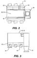
- Figure 2 shows schematically in top plan view, the mud separation unit 15 with scalper screen 22 in the flow divider box 10 and the arrangement of the discharge chute 25, collector boxes 23, baffle plates 16, and cylindrical discharge flow lines 19.
- the continuous loop scalper screen 22 of the mud separation unit 15 discharges large amounts of drill solids off of the discharge end of the flow divider box 10 and separates formation cuttings, sediments, silt, and sand through the openings of the scalper screen 22 while redistributing the aforementioned with drilling fluid or drilling mud to the collector boxes 23 via the cylindrical discharge flow lines 19 to shale shakers, desilters, desanders, mud cleaners, centrifuge or other downstream solids control equipment in the mud system of the drilling rig.
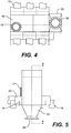
- Figure 4 shows the divider box 10 from the bottom and the arrangement of the opposing cylindrical discharge flow lines 19, the radial discharge flange 26, discharge chute 25, and radial clean-out flange 18.
- Figure 5 shows, in partial cross section, the discharge chute 25 and radial discharge flange 26 that direct the heavy clays, gumbo and other large drill solids overboard or into a reserve pit.
- the collector boxes 23 and baffle plates 16 provide hydrostatic head end even distribution, or selected distribution by deployment of the gates 17 channeling the drilling fluid or drilling mud via the offset cylindrical discharge flow lines 19, downstream to the shale shakers or other solids control equipment.
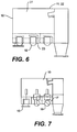
- Figure 6 is a cross section view taken along the line A-A of Figure 5, showing the wall 27 of the flow of solids off the separation units end as the continuous loop scalper screen 22 completes its cycle.
- the collector boxes 23 redistribute sediments, drilling fluid, and drilling mud, through cylindrical discharge flow lines 19 to the shale shakers or other equipment installed downstream as part of the conventional solids control equipment.
- Figure 7 illustrates the positions of the various gates 17.
- the sliding gates 17 are analogous to a variable choke, whereby the autonomous controlled gate can be open, closed, or be positioned at various increments therebetween.
- the drilling fluid or drilling mud is conveyed, by sundry ports or individual port via the cylindrical discharge flow lines 19 to the downstream shale shakers, desilter, desander, centrifuge, or other conventional downstream solid control equipment, which are part of the mud system of the oil and gas drilling rig.
- the raised face radial clean out flange 18 is an integral part of the flow divider box 10 and allows for high pressure jetting and easy removal of the silt and sediments.
- the flow divider box 10 has a box cover 53 and an electric motor-gear reduction box 37 mounted parallel to the rectangular flow divider box which is connected to the belt 49 driven, drive sheave 38, and retaining hub 50 coupled to the front axle 39 of the mud separation unit by means of key 40 and keyway 41.
- the key 40 serves as the mechanical link between the drive sheave 38, retaining hub 50, and the axle 39.
- the mud separation unit 15 includes: an outer frame 27, front tension frame 28, rear tension frame 29, placement bars 30, chain cover bracket 31, chain wiper 32, tensioning system 33, drive roller 34, rear roller 35, hydraulic reservoir 36, motor-gear reduction box 37, drive sheave 38, axle 39, key 40, keyway 41, and bearing housing 42, and drives a wide endless-belt scalper screen 22, mesh screen scalper 43, or combination thereof 44 in a continuous loop.
- the separation unit 15 has an outer frame 27, front tension frame, rear tension frame 29, tensioning system 33, rear roller 35, and a drive roller 34 having an axle connected with the motor-gear reduction box 37 of the flow divider box to rotate the continuous-loop scalper screen 22 along the longitudinal axis of the outer frame 27.
- the scalper screen 22 is removably installed by a circular parallel shaft 45, secured by nut 46.
- the mud separation unit 15 is geometrically supported on inclined rails 24 in the side walls of the flow divider box 10 and disposed in the flow path of the return flow line of the oil and gas drilling rig.
- Elements 22, 27, 28, 29, 34, 35, 36, 39, 42, 45, 46, 47, and 48 are components of the tensioning system 33 of the mud separation unit 15.
- the mud separation unit 15 serves to convey and discharge gumbo, large drill solids, or heavy clays from the drilling fluid or drilling mud circulating out of the well bore.
- the front tension frame 28 supporting the drive roller 34 on axle 39 through bearing housing 42, plate 56, and plate 57 are affixed to the outer frame 27 by bolts 52.
- the rear roller 35, axle 55, and bearing housing 42 are affixed to the rear tension frame 29 by bolts 55.
- the flow divider box 10 embodying the separation unit 15 moves the scalper screen 22 along the longitudinal axis of the flow divider box.
- the drill solids conveyed on the continuous loop scalper screen 22 are discharged off the end of the separation unit as the moving scalper screen repeats its cycle.
- the flow divider box 10 separates and redistributes drilling fluid and drilling mud, sustains silt and sediments, and reclaims weight materials and chemicals, and thus minimizes fluid loss and optimizes the mud reclaiming program and operation of the convention upstream solids control equipment.
Abstract
Description
- The invention relates to a flow divider box embodying a separation unit driving a scalper screen for the removal and separation of sticky shales, heavy clays, or large amounts of drill solids from the drilling mud or drilling fluid in the mud returns circulating out of an oil and gas well bore. A flow divider box typically includes or communicates with an array of collector boxes containing baffle plates and adjustable gates regulating the fluid flow redistribution of the drilling fluid or drilling mud to independent shakers.
- The mud system is an integral part of an oil and gas drilling rig, land or marine. Drilling mud or drilling fluid is continually recycled because of the huge cost factor and for environmental reasons. The drilling mud or drilling fluid is used to hold formation pressures in balance, to create and maintain well bore filter cake, create hydraulic horsepower at the bit, hydrostatic testing, shifting of spherical valve elements downhole, and removal of formation solids, cuttings, sand, etc., through the mud return annulus. As the drilling mud or drilling fluid flows from the bell nipple flow line its solids content is refined and removed, through a series of solids control equipment, each removing or separating the plate-like mica structure to a smaller physical size.
- It is of the utmost advantage to remove as much solids as practical to reduce down time resulting from plugged flow lines, fluid end repair, drill string erosion, redrilling of the solids or sediments as the drilling mud or drilling fluid recycles itself through the mud system loop.
- The conventional mechanical solids control equipment used for removing solids from drilling mud or drilling fluid involves shale shakers and vibratory screens, desilters, desanders, mud cleaners, and centrifuge. This equipment operates at different levels of particle size rejecting solids and retaining desirable solids which can be part of the drilling mud or drilling fluid additives or chemicals.
- The mechanical shale shaker screens are limited to short life, and the screens become coated with sticky clays closing the pores or mesh openings resulting in fluid or mud loss. This adds to the problem as additional water must be added to the drilling mud system. This involves the addition of chemical and mud additives to restore the correct and desired mud properties and mud weight, hence the cost of drilling is increased.
- The invention is broadly defined in
independent claims 1 and 13. Further, optional features of the invention are defined in the dependent claims. - The present invention overcomes one or more drawbacks and disadvantages of the prior art and provides additional advantages as well.
- The present invention is installed in the flow path of the drilling mud or drilling fluid in the mud system of a drilling rig, upstream of the conventional solids control equipment, and while drilling virgin or young shales it separates and discharges large amounts of drill solids, gumbo, and heavy clays, from the drilling mud or drilling fluid prior to drilling mud or drilling fluid flowing to the aforementioned conventional solids control equipment.
- Now by employing a flow divider box in the drilling mud or drilling fluid flow path line, the sediments are managed through an array of individual collector boxes containing baffle plates and gates that regulate the fluid flow redistribution of the sediments in suspension in the drilling mud or drilling fluid before being individually channeled through cylindrical discharge lines.
- The present invention is equipped with manual or hydraulic gates adjustable to compliment the drilling program as to gallons per minute pumped, and the drilling fluids program itself. The flow divider box having an array of collector boxes supplies drilling mud or drilling fluid to individual shale shakers, and embodies a removal cartridge type separation unit geometrically installed in the flow divider box, that removes large amounts of drill solids, gumbo, and heavy clays from the drilling mud or drilling fluid upstream of the conventional shale shakers.
- The following description concerns preferred embodiments of the invention.
- A flow divider box disposed beneath a continuous-loop scalper screen mud separation unit that conveys and discharges large amounts of drill solids at the end of the separation unit serves as first line separation equipment in the flow path of drilling fluid or drilling mud to separate drilled solids and redistribute sediments and drilling fluid and drilling mud to selected shale shakers and other conventional solids control equipment. The flow divider box and mud separation unit is positioned in the fluid flow path of the drilling fluid or drilling mud, upstream of the conventional solids control equipment.
- The mud separation unit is removably installed in the flow divider box and is equipped with a wide tensioned mud scalper screen driven in a continuous loop around a toothed drive roller and a rear roller propelled by a motor through a gear reduction box. The separation unit is geometrically positioned on rails a predetermined distance apart on the sides of the flow divider box at an angle less than vertical.
- The flow divider box has an attached discharge chute to direct drill solids or gumbo overboard or into a reserve pit, a large cleanout flange parallel with the bottom of the flow divider box for the removal of sediments, and cylindrical discharge flow lines.
- The flow divider box contains individual independent collector boxes employing a sliding gate that are adjustably positioned to regulate the fluid flow redistribution of the drilling fluid or drilling mud. The gates allow the drilling fluid or drilling mud to rise to baffle or gauge level, creating a hydrostatic head column at the cylindrical discharge flow lines.
- The cylindrical discharge flow lines are of sized diameters and are offset from the bottom centerline of the flow divider box. Full advantage of the volume and hydrostatic head is taken of the drilling fluid or drilling mud to move silt and sediments away from the concave openings of the cylindrical discharge flow lines and the box bottom to optimize the self-cleaning feature.
- The flow divider box compliments the drilling program as to the number of shale shakers, etc., in operation, gallons per minute pumped, hole size, annular velocity, and the drilling fluids program, as the continuous loop scalper screen moves along the longitudinal axis of the flow divider box redistributing sediments, drilling fluid and drilling mud through an array of autonomous collector boxes, into cylindrical discharge flow lines conveying the sediments, drilling fluid and drilling mud to the downstream solids control equipment, shale shakers, desilters, desanders, etc.
- There now follows a description of preferred embodiments of the invention, by way of non-limiting example, with reference being made to the accompanying drawings in which:
- Figure 1 is an isometric drawing of the flow divider box in accordance with the present invention;
- Figure 2 is a top plan view of the flow divider box;
- Figure 3 is a side elevation view of the flow divider box;
- Figure 4 is a bottom plan view of the flow divider box;
- Figure 5 is an end view of the flow divider box shown partially in cross section;
- Figure 6 is a cross section view taken along the line A-A of Figure 5;
- Figure 7 is a side view of flow divider box showing the gates extended;
- Figure 8 is an isometric view showing the power source of the flow divider box;
- Figure 9 is an isometric view of the continuous-loop mud separation unit; and
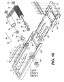
- Figure 10 is an exploded isometric view of the mud separation unit.
-
-
- 10. Flow divider box
- 15. Separation unit
- 16. Baffle plates
- 17. Gate
- 18. Clean-out Flange
- 19. Cylindrical discharge flow line
- 21. Flow line flange
- 22. Scalper Screen
- 23. Collector boxes
- 24. Rails
- 25. Discharge chute
- 26. Discharge flange
- 27. Outer frame
- 28. Front tension frame
- 29. Rear tension frame
- 30. Placement bars
- 31. Chain cover bracket
- 32. Chain wiper
- 33. Tension system
- 34. Drive roller
- 35. Rear roller
- 36. Hydraulic reservoir
- 37. Motor-gear reduction box
- 38. Drive sheave
- 39. Axle, drive
- 40. Key
- 41. Keyway
- 42. Bearing housing
- 43. Mesh screen scalper
- 44. Combination thereof
- 45. Circular parallel shaft
- 46. Nut
- 47. Hydraulic cylinders
- 48. Air-line
- 49. Belt
- 50. Retaining hub
- 51. Circular parallel shafts
- 52. Bolts
- 53. Box cover
- 54. Axle, rear roller
- 55. Bolts
- 56. Plate
- 57. Plate
- 58. Motor housing
- 59. Collar
-
- As is conventional in the prior art, mixing tanks, holding tanks, flow lines, mud mixers, shale shakers, desilters, desanders, centrifuge are part of an integrated mud system, typical of the downstream solids control equipment on a drilling rig. When drilling in young or virgin shales, a sticky substance known as gumbo is often encountered. The gumbo shale can be of large volume and, because it comprises positive ions, when wet becomes very stick, impervious and plastic. Thus, it is desirable to separate and discharge the gumbo quickly and efficiently.
- The present flow divider box is installed in the flow path of drilling fluid or drilling mud upstream from the conventional solids control equipment and used in connection with a mud separation unit moving a scalper screen installed in the flow path of the drilling mud or drilling fluid to convey, separate, and discharge sticky shales overboard or into a reserve pit prior to it reaching the conventional solids control equipment. The apparatus distributes fluid flow through a sundry of baffled collector boxes and autonomously supplies a plurality of shale shakers, etc., through an array of cylindrical discharge flow lines, simultaneously or selectively as designated by a drilling fluids program.
- Referring now to the drawings by numerals of reference, there is shown in Figure 1, a
flow divider box 10 which is installed in the drilling fluids flow path or mud system of an oil and gas drilling rig, lane or marine, upstream from the conventional solids control equipment, such as shale shakers, desilters, desanders, etc. Theflow divider box 10 regulates drilling fluid or drilling mud to one or more downstream shale shakers, desilters, desanders, etc., simultaneously increasing or decreasing the fluid flow, independently and selectively through the manipulation ofgates 17 disposed within theflow divider box 10. The mud separation unit having a scalper screen 22 is removably mounted at the top of theflow divider box 10 in the flow path of the drilling mud or drilling fluid and serves to remove drilling solids, gumbo, and heavy clays. Themud separation unit 15 and screen 22 are shown schematically in Figures 1 and 2, but are described in detail hereinafter with reference to Figures 9 and 10. The drilling fluid or drilling mud enters theflow divider box 10 through theflow line flange 21 and is laminated by the circular parallel shafts 51. The drilling fluid, drilling mud, and sediments filter through the scalper screen 22, to be conveyed, separated, and redistributed within thecollector boxes 23, via the cylindricaldischarge flow lines 19 to downstream shale shakers for the removal of ultra fine silt and sediments, within the drilling fluid and drilling mud circulating out of a well bore. - The
flow divider box 10 conveys, separates, or redistributes a continuous fluid flow stream of drilling fluid or drilling mud toautonomous collector boxes 23 arrayed bybaffle plates 16 to form individual collector chambers, regulated bygates 17 varying in dimension and profile. Thegates 17 are adjustable for predetermined fluid flow rates, changes in fluid flow rates, mud weights, mud properties, viscosity, lithology, and formation change. The cylindricaldischarge flow lines 19 are perpendicular to the opposinggates 17. The diameter of the cylindricaldischarge flow lines 19 are of predetermined size. The individual cylindricdischarge flow lines 19 are offset at the bottom centerline of theflow divider box 10 in an arrayed collector system of cylindricaldischarge flow lines 19 conveying formation cuttings sediments, drilling fluid and drilling mud to the shale shakers, etc., as required. - Figure 2 shows schematically in top plan view, the
mud separation unit 15 with scalper screen 22 in theflow divider box 10 and the arrangement of thedischarge chute 25,collector boxes 23,baffle plates 16, and cylindricaldischarge flow lines 19. - As seen in Figures 3-8, the continuous loop scalper screen 22 of the
mud separation unit 15 discharges large amounts of drill solids off of the discharge end of theflow divider box 10 and separates formation cuttings, sediments, silt, and sand through the openings of the scalper screen 22 while redistributing the aforementioned with drilling fluid or drilling mud to thecollector boxes 23 via the cylindricaldischarge flow lines 19 to shale shakers, desilters, desanders, mud cleaners, centrifuge or other downstream solids control equipment in the mud system of the drilling rig. - Figure 4 shows the
divider box 10 from the bottom and the arrangement of the opposing cylindricaldischarge flow lines 19, theradial discharge flange 26,discharge chute 25, and radial clean-outflange 18. - Figure 5 shows, in partial cross section, the
discharge chute 25 andradial discharge flange 26 that direct the heavy clays, gumbo and other large drill solids overboard or into a reserve pit. Thecollector boxes 23 andbaffle plates 16 provide hydrostatic head end even distribution, or selected distribution by deployment of thegates 17 channeling the drilling fluid or drilling mud via the offset cylindricaldischarge flow lines 19, downstream to the shale shakers or other solids control equipment. - Figure 6 is a cross section view taken along the line A-A of Figure 5, showing the
wall 27 of the flow of solids off the separation units end as the continuous loop scalper screen 22 completes its cycle. Thecollector boxes 23 redistribute sediments, drilling fluid, and drilling mud, through cylindricaldischarge flow lines 19 to the shale shakers or other equipment installed downstream as part of the conventional solids control equipment. - Figure 7 illustrates the positions of the
various gates 17. The slidinggates 17 are analogous to a variable choke, whereby the autonomous controlled gate can be open, closed, or be positioned at various increments therebetween. The drilling fluid or drilling mud is conveyed, by sundry ports or individual port via the cylindricaldischarge flow lines 19 to the downstream shale shakers, desilter, desander, centrifuge, or other conventional downstream solid control equipment, which are part of the mud system of the oil and gas drilling rig. - During the continuous operational phase of drilling an oil and gas well there can be a build-up of the sediments in solids control equipment. The raised face radial clean out
flange 18 is an integral part of theflow divider box 10 and allows for high pressure jetting and easy removal of the silt and sediments. - As seen in Figure 8, the
flow divider box 10 has a box cover 53 and an electric motor-gear reduction box 37 mounted parallel to the rectangular flow divider box which is connected to the belt 49 driven,drive sheave 38, and retaininghub 50 coupled to the front axle 39 of the mud separation unit by means of key 40 andkeyway 41. The key 40 serves as the mechanical link between thedrive sheave 38, retaininghub 50, and the axle 39. - Referring now to Figures 9 and 10, the
mud separation unit 15 includes: anouter frame 27,front tension frame 28,rear tension frame 29, placement bars 30,chain cover bracket 31,chain wiper 32, tensioning system 33,drive roller 34,rear roller 35,hydraulic reservoir 36, motor-gear reduction box 37,drive sheave 38, axle 39, key 40,keyway 41, and bearinghousing 42, and drives a wide endless-belt scalper screen 22, mesh screen scalper 43, or combination thereof 44 in a continuous loop. Theseparation unit 15 has anouter frame 27, front tension frame,rear tension frame 29, tensioning system 33,rear roller 35, and adrive roller 34 having an axle connected with the motor-gear reduction box 37 of the flow divider box to rotate the continuous-loop scalper screen 22 along the longitudinal axis of theouter frame 27. The scalper screen 22 is removably installed by a circularparallel shaft 45, secured bynut 46. Themud separation unit 15 is geometrically supported on inclined rails 24 in the side walls of theflow divider box 10 and disposed in the flow path of the return flow line of the oil and gas drilling rig. -
Elements mud separation unit 15. - The
mud separation unit 15 serves to convey and discharge gumbo, large drill solids, or heavy clays from the drilling fluid or drilling mud circulating out of the well bore. The scalper screen 22 of themud separation unit 15, while conveying and discharging solids, reclaims the drilling mud or drilling fluid along with the weight material and chemicals therewithin, by allowing the drilling mud or drilling fluids to pass through the array of openings of the scalper screen thereby reducing mud and chemical cost and reducing logistical problems through reduced mud and chemical usage. - As best seen in Figure 10, parallel air/oil
hydraulic cylinders 47,air line 48, andcollar 59 with cylinder rods extended apply and maintain tension to the slidingrear tension frame 29 supporting therear roller 35. Thefront tension frame 28 supporting thedrive roller 34 on axle 39 extending throughjournalled bearing housings 42 is affixed to theouter frame 27 bybolts 52. Therear tensioning frame 29 moves independently within theouter frame 27, varying in location to the fixedfront tension frame 28,hydraulic reservoir 36, and drivesprocket 34 by extending or retracting the cylinder rods. With the cylinder rods extended, therear tensioning frame 29 andrear roller 35 traverse to apply and maintain tension on the rotating continuous loop scalper screen 22, mesh screen scalper 43, orcombination thereof 44. - The
front tension frame 28 supporting thedrive roller 34 on axle 39 through bearinghousing 42,plate 56, andplate 57 are affixed to theouter frame 27 bybolts 52. Therear roller 35, axle 55, and bearinghousing 42 are affixed to therear tension frame 29 by bolts 55. - The
flow divider box 10 embodying theseparation unit 15 moves the scalper screen 22 along the longitudinal axis of the flow divider box. The drill solids conveyed on the continuous loop scalper screen 22 are discharged off the end of the separation unit as the moving scalper screen repeats its cycle. Theflow divider box 10 separates and redistributes drilling fluid and drilling mud, sustains silt and sediments, and reclaims weight materials and chemicals, and thus minimizes fluid loss and optimizes the mud reclaiming program and operation of the convention upstream solids control equipment. - Other embodiments of the present invention will be apparent to those skilled in the art from consideration of the specification and practice of the invention disclosed herein. It is intended that the specification and examples be considered as exemplary only.
Claims (16)
- A flow divider box for separating and distributing drilling fluid, drilling mud, and the like, to selected solids control equipment, comprising:means for receiving solids-containing drilling fluid and drilling means;means for separating drilling solids therefrom;a plurality of independent, separate means for regulating and distributing said drilling fluid and drilling mud from said separating means to said selected solids control equipment; andmeans for separately discharging from said flow divider box said drilling solids separated from said drilling fluid and said drilling mud.
- The flow divider box of claim 1, wherein said regulating and distributing means comprises a plurality of independent, separate collector chambers for receiving separated drilling fluid and drilling mud from said separating means and each said separate collector chamber having a separate flow line with each thereof adapted for connection to selected solids control equipment.
- The flow divider box of claim 2, wherein each said separate collector chamber has separate and independent means for regulating flow of said separated drilling fluid and drilling mud from said separating means through each separate flow line.
- The flow divider box of claim 3, wherein said flow regulating means comprises an adjustable sliding gate.
- The flow divider box of claim 4, wherein said separate collector chamberrs are separated by a plurality of baffles along a bottom portion of said flow divider box.
- The flow divider box of any preceding claim, wherein said discharging means comprises a chute attached to said flow divider box and adapted to direct said separated drilling solids out of said flow divider box.
- The flow divider box of any preceding claim, wherein said means for separating drilling solids comprises a mud separation apparatus removably installed in said flow divider box.
- The flow divider box of claim 7, wherein said mud separation apparatus comprises a continuous loop mud scalper screen, a drive roller in driving engagement with said screen and means for driving said drive roller.
- The flow divider box of claim 8, wherein said drive roller has teeth extending into openings in said screen.
- The flow divider box of claim 9, wherein said driving means comprises a motor and associated gear reduction box.
- The flow divider box of claim 7 or any claim dependent therefrom, wherein said mud separation apparatus is removably installed in said flow divider box at an angle less than vertical.
- The flow divider box of any preceding claim, wherein means integral with said flow divider box is provided for connection to a means for producing a high pressure jet for cleaning said flow divider box.
- A flow divider box for separating and distributing drilling fluid, drilling mud, and the like to selected solids control equipment, comprising:an opening in said flow divider box for receiving solids-containing drilling fluid and drilling mud;a mud separating apparatus removably installed in said flow divider box and positioned to receive said solids-containing drilling fluid and drilling mud from said opening for separating drilling solids therefrom;a plurality of independent, separate collector chambers for receiving separated drilling fluid and drilling mud from said mud separating apparatus, with each of said collector chambers having separate and independent means for regulating flow of said separated drilling fluid and drilling mud through separate flow lines of each of said collector chambers connected to selected solids control equipment; anda chute attached to said flow divider box for directing separated drilling solids out of said flow divider box.
- The flow divider box of claim 13, wherein said flow regulating means comprises an adjustable sliding gate.
- The flow divider box of claim 14, wherein said mud separating apparatus comprises a continuous loop scalper screen, a drive roller in driving engagement with said screen, and means for driving said drive roller.
- The flow divider of claim 15, wherein said drive roller has teeth extending into openings in said screen.
Priority Applications (1)
| Application Number | Priority Date | Filing Date | Title |
|---|---|---|---|
| DK98307717T DK0907003T3 (en) | 1997-10-03 | 1998-09-23 | Power divider box to guide drill mud to specific drill mud separators |
Applications Claiming Priority (2)
| Application Number | Priority Date | Filing Date | Title |
|---|---|---|---|
| US6094097P | 1997-10-03 | 1997-10-03 | |
| US60940P | 1997-10-03 |
Publications (2)
| Publication Number | Publication Date |
|---|---|
| EP0907003A1 true EP0907003A1 (en) | 1999-04-07 |
| EP0907003B1 EP0907003B1 (en) | 2004-08-25 |
Family
ID=22032682
Family Applications (1)
| Application Number | Title | Priority Date | Filing Date |
|---|---|---|---|
| EP98307717A Expired - Lifetime EP0907003B1 (en) | 1997-10-03 | 1998-09-23 | Flow divider box for conducting drilling mud to selected drilling mud separation units |
Country Status (8)
| Country | Link |
|---|---|
| US (1) | US6223906B1 (en) |
| EP (1) | EP0907003B1 (en) |
| BR (1) | BR9803956A (en) |
| CA (1) | CA2248749C (en) |
| DE (1) | DE69825832T2 (en) |
| DK (1) | DK0907003T3 (en) |
| NO (1) | NO315718B1 (en) |
| SG (1) | SG74661A1 (en) |
Cited By (3)
| Publication number | Priority date | Publication date | Assignee | Title |
|---|---|---|---|---|
| EP0908599A2 (en) * | 1997-10-09 | 1999-04-14 | J. Terrell Williams | Bypass diverter box for drilling mud separation unit |
| WO2013116716A1 (en) * | 2012-02-03 | 2013-08-08 | M-I L.L.C. | Multi-deck vibratory separator with series and parallel fluid processing capabilities |
| CN111395982A (en) * | 2020-04-29 | 2020-07-10 | 中建八局第二建设有限公司 | Anti-floating anchor rod drilling construction mud collection device |
Families Citing this family (34)
| Publication number | Priority date | Publication date | Assignee | Title |
|---|---|---|---|---|
| US6530482B1 (en) * | 2000-04-26 | 2003-03-11 | Michael D. Wiseman | Tandem shale shaker |
| US20050242003A1 (en) | 2004-04-29 | 2005-11-03 | Eric Scott | Automatic vibratory separator |
| US8312995B2 (en) | 2002-11-06 | 2012-11-20 | National Oilwell Varco, L.P. | Magnetic vibratory screen clamping |
| US8172740B2 (en) * | 2002-11-06 | 2012-05-08 | National Oilwell Varco L.P. | Controlled centrifuge systems |
| US8118172B2 (en) * | 2005-11-16 | 2012-02-21 | National Oilwell Varco L.P. | Shale shakers with cartridge screen assemblies |
| MX2008013608A (en) | 2006-05-26 | 2009-02-12 | Nat Oilwell Varco Lp | Apparatus and method for separtating solids from a solids laden liquid. |
| US20080083566A1 (en) | 2006-10-04 | 2008-04-10 | George Alexander Burnett | Reclamation of components of wellbore cuttings material |
| US8231010B2 (en) | 2006-12-12 | 2012-07-31 | Varco I/P, Inc. | Screen assemblies and vibratory separators |
| US8622220B2 (en) | 2007-08-31 | 2014-01-07 | Varco I/P | Vibratory separators and screens |
| US7980392B2 (en) | 2007-08-31 | 2011-07-19 | Varco I/P | Shale shaker screens with aligned wires |
| US8133164B2 (en) * | 2008-01-14 | 2012-03-13 | National Oilwell Varco L.P. | Transportable systems for treating drilling fluid |
| US9073104B2 (en) | 2008-08-14 | 2015-07-07 | National Oilwell Varco, L.P. | Drill cuttings treatment systems |
| US20100038143A1 (en) * | 2008-08-14 | 2010-02-18 | George Alexander Burnett | Drill cuttings treatment systems |
| US9079222B2 (en) | 2008-10-10 | 2015-07-14 | National Oilwell Varco, L.P. | Shale shaker |
| US8556083B2 (en) | 2008-10-10 | 2013-10-15 | National Oilwell Varco L.P. | Shale shakers with selective series/parallel flow path conversion |
| US8113356B2 (en) * | 2008-10-10 | 2012-02-14 | National Oilwell Varco L.P. | Systems and methods for the recovery of lost circulation and similar material |
| US7886850B2 (en) * | 2008-10-10 | 2011-02-15 | National Oilwell Varco, L.P. | Drilling fluid screening systems |
| BRPI0823251B1 (en) * | 2008-11-03 | 2018-08-14 | Exxonmobil Upstream Research Company | FLOW CONTROL SYSTEM AND APPARATUS, AND METHOD FOR CONTROLING PARTICULATE FLOW IN HYDROCARBON WELL EQUIPMENT |
| NO20100746A1 (en) * | 2010-05-20 | 2011-09-05 | Optipro As | An improved inlet channel for liquid and particle distribution for a well fluid screening machine |
| EP2616627A4 (en) | 2010-09-15 | 2014-12-03 | Mi Llc | Feeder with screen for shaker |
| WO2012037301A2 (en) * | 2010-09-15 | 2012-03-22 | M-I L.L.C. | Return fluid separator |
| US8622135B2 (en) * | 2010-10-05 | 2014-01-07 | Cooper Smartt | Apparatus and methods for separating sand from well fracturing return water |
| SG10201602806RA (en) | 2011-10-12 | 2016-05-30 | Exxonmobil Upstream Res Co | Fluid filtering device for a wellbore and method for completing a wellbore |
| US9643111B2 (en) | 2013-03-08 | 2017-05-09 | National Oilwell Varco, L.P. | Vector maximizing screen |
| US9725989B2 (en) | 2013-03-15 | 2017-08-08 | Exxonmobil Upstream Research Company | Sand control screen having improved reliability |
| WO2014149396A2 (en) | 2013-03-15 | 2014-09-25 | Exxonmobil Upstream Research Company | Apparatus and methods for well control |
| US10240412B2 (en) | 2014-12-23 | 2019-03-26 | Vermeer Manufacturing Company | Drilling fluid processing tank and system |
| WO2016168375A1 (en) * | 2015-04-15 | 2016-10-20 | Schlumberger Norge As | Method and system for fluid level measurement |
| CN106955840B (en) * | 2017-05-08 | 2023-02-03 | 长江大学 | Vibrating screen for drilling fluid mud |
| CN107555752B (en) * | 2017-09-08 | 2023-09-19 | 三川德青工程机械有限公司 | Underflow hopper, mud treatment system and method |
| CN111991914B (en) * | 2020-07-28 | 2022-09-13 | 四川中创石油设备有限公司 | Full-automatic flow distribution box and flow distribution method |
| CN112619256B (en) * | 2021-01-07 | 2022-06-21 | 湖南国辰环保科技有限公司 | Environment-friendly energy-saving urban domestic sewage treatment device |
| CN114477711B (en) * | 2022-03-03 | 2023-06-30 | 中铁五局集团第一工程有限责任公司 | Sludge treatment system |
| US11959343B2 (en) * | 2022-09-12 | 2024-04-16 | Workover Solutions, Inc. | Drilling system with annular flush separation device and method |
Citations (4)
| Publication number | Priority date | Publication date | Assignee | Title |
|---|---|---|---|---|
| US3777405A (en) * | 1972-04-17 | 1973-12-11 | T Crawford | Drilling mud reclaiming apparatus |
| US4493382A (en) * | 1983-08-25 | 1985-01-15 | Gus Pech Manufacturing Co. | Vehicle-mounted earth drilling apparatus |
| US4639258A (en) * | 1983-10-14 | 1987-01-27 | Leon E. Roy | Single pass mud rejuvenation system and method |
| US4753633A (en) * | 1986-11-28 | 1988-06-28 | Stephen R. Callegari, Sr. | Slurry separator |
Family Cites Families (8)
| Publication number | Priority date | Publication date | Assignee | Title |
|---|---|---|---|---|
| US4378056A (en) * | 1981-09-23 | 1983-03-29 | Gay Jr Cleveland J | Method and apparatus for balancing discharge fluid flow in drilling mud treatment units |
| US4670139A (en) * | 1986-06-19 | 1987-06-02 | Spruiell Walter L | Drilling mud cleaning machine |
| NL8602703A (en) * | 1986-06-19 | 1988-01-18 | Mudcleaning Services | METHOD FOR WINNING A BASIC SUSPENSION SUITABLE FOR PREPARING A DRILL FLUSH SUSPENSION USED WHEN ROTATING DRILLING A HOLE IN THE EARTH GROUND, FROM FINISHED SUSPENSION ARISING FROM DRILLING. |
| US4911834A (en) * | 1988-10-27 | 1990-03-27 | Triton Engineering Services Company | Drilling mud separation system |
| US4940535A (en) * | 1988-11-28 | 1990-07-10 | Amoco Corporation | Solids flow distribution apparatus |
| US5919358A (en) * | 1996-05-06 | 1999-07-06 | Williams; J. Terrell | Continuous-belt drilling mud separation system |
| US5996387A (en) * | 1997-10-07 | 1999-12-07 | Williams; J. Terrell | Method and apparatus for pre-stretching continuous chain-link drilling mud separation belt |
| US6024228A (en) * | 1997-10-09 | 2000-02-15 | Tuboscope Nu-Tec/Gnt | Bypass diverter box for drilling mud separation unit |
-
1998
- 1998-09-03 US US09/146,670 patent/US6223906B1/en not_active Expired - Lifetime
- 1998-09-17 SG SG1998003707A patent/SG74661A1/en unknown
- 1998-09-23 EP EP98307717A patent/EP0907003B1/en not_active Expired - Lifetime
- 1998-09-23 DK DK98307717T patent/DK0907003T3/en active
- 1998-09-23 DE DE69825832T patent/DE69825832T2/en not_active Expired - Lifetime
- 1998-09-29 CA CA002248749A patent/CA2248749C/en not_active Expired - Lifetime
- 1998-09-30 NO NO19984571A patent/NO315718B1/en not_active IP Right Cessation
- 1998-10-01 BR BR9803956-3A patent/BR9803956A/en active IP Right Grant
Patent Citations (4)
| Publication number | Priority date | Publication date | Assignee | Title |
|---|---|---|---|---|
| US3777405A (en) * | 1972-04-17 | 1973-12-11 | T Crawford | Drilling mud reclaiming apparatus |
| US4493382A (en) * | 1983-08-25 | 1985-01-15 | Gus Pech Manufacturing Co. | Vehicle-mounted earth drilling apparatus |
| US4639258A (en) * | 1983-10-14 | 1987-01-27 | Leon E. Roy | Single pass mud rejuvenation system and method |
| US4753633A (en) * | 1986-11-28 | 1988-06-28 | Stephen R. Callegari, Sr. | Slurry separator |
Cited By (4)
| Publication number | Priority date | Publication date | Assignee | Title |
|---|---|---|---|---|
| EP0908599A2 (en) * | 1997-10-09 | 1999-04-14 | J. Terrell Williams | Bypass diverter box for drilling mud separation unit |
| EP0908599A3 (en) * | 1997-10-09 | 2000-08-30 | J. Terrell Williams | Bypass diverter box for drilling mud separation unit |
| WO2013116716A1 (en) * | 2012-02-03 | 2013-08-08 | M-I L.L.C. | Multi-deck vibratory separator with series and parallel fluid processing capabilities |
| CN111395982A (en) * | 2020-04-29 | 2020-07-10 | 中建八局第二建设有限公司 | Anti-floating anchor rod drilling construction mud collection device |
Also Published As
| Publication number | Publication date |
|---|---|
| US6223906B1 (en) | 2001-05-01 |
| NO984571L (en) | 1999-04-06 |
| DE69825832D1 (en) | 2004-09-30 |
| NO315718B1 (en) | 2003-10-13 |
| NO984571D0 (en) | 1998-09-30 |
| CA2248749C (en) | 2005-11-22 |
| DK0907003T3 (en) | 2004-12-06 |
| EP0907003B1 (en) | 2004-08-25 |
| DE69825832T2 (en) | 2005-08-18 |
| CA2248749A1 (en) | 1999-04-03 |
| BR9803956A (en) | 1999-12-28 |
| SG74661A1 (en) | 2000-08-22 |
Similar Documents
| Publication | Publication Date | Title |
|---|---|---|
| CA2248749C (en) | Flow divider box for conducting drilling mud to selected drilling mud separation units | |
| EP0908599B1 (en) | Bypass diverter box for drilling mud separation unit | |
| US9079222B2 (en) | Shale shaker | |
| CA2445067C (en) | Method and apparatus for removing fluids from drill cuttings | |
| CA2253350C (en) | Continuous belt drilling mud separation system | |
| US6530482B1 (en) | Tandem shale shaker | |
| US6244362B1 (en) | Weir box for drilling mud separation unit | |
| US8695809B2 (en) | Return drilling fluid processing | |
| US7857077B2 (en) | Method and apparatus for processing and injecting drill cuttings | |
| BRPI0621570A2 (en) | method for separating solids from a solids-loaded drilling mud and mechanism for separating solids from a solids-loaded drilling mud | |
| US6162284A (en) | Separator for gases, liquids and solids from a well | |
| WO2009074818A1 (en) | A method and apparatus for processing solids laden drilling mud having lost circulation material therein | |
| EP2310619B1 (en) | Cuttings transfer system | |
| US5788621A (en) | Method and apparatus for centrifugal separation of solids from mud and compaction | |
| CA2737406A1 (en) | Method and apparatus for separating solids from solids laden drilling fluid | |
| US20170130541A1 (en) | Series and parallel separation device | |
| MX2013002966A (en) | Return fluid separator. | |
| US2348664A (en) | Conveyer | |
| WO1997048494A1 (en) | Method and apparatus for separating solids from drilling mud |
Legal Events
| Date | Code | Title | Description |
|---|---|---|---|
| PUAI | Public reference made under article 153(3) epc to a published international application that has entered the european phase |
Free format text: ORIGINAL CODE: 0009012 |
|
| AK | Designated contracting states |
Kind code of ref document: A1 Designated state(s): DE DK FR GB NL |
|
| AX | Request for extension of the european patent |
Free format text: AL;LT;LV;MK;RO;SI |
|
| 17P | Request for examination filed |
Effective date: 19990918 |
|
| AKX | Designation fees paid |
Free format text: DE DK FR GB NL |
|
| 17Q | First examination report despatched |
Effective date: 20021028 |
|
| GRAP | Despatch of communication of intention to grant a patent |
Free format text: ORIGINAL CODE: EPIDOSNIGR1 |
|
| GRAS | Grant fee paid |
Free format text: ORIGINAL CODE: EPIDOSNIGR3 |
|
| GRAA | (expected) grant |
Free format text: ORIGINAL CODE: 0009210 |
|
| AK | Designated contracting states |
Kind code of ref document: B1 Designated state(s): DE DK FR GB NL |
|
| REG | Reference to a national code |
Ref country code: GB Ref legal event code: FG4D |
|
| REF | Corresponds to: |
Ref document number: 69825832 Country of ref document: DE Date of ref document: 20040930 Kind code of ref document: P |
|
| REG | Reference to a national code |
Ref country code: DK Ref legal event code: T3 |
|
| ET | Fr: translation filed | ||
| PLBE | No opposition filed within time limit |
Free format text: ORIGINAL CODE: 0009261 |
|
| STAA | Information on the status of an ep patent application or granted ep patent |
Free format text: STATUS: NO OPPOSITION FILED WITHIN TIME LIMIT |
|
| 26N | No opposition filed |
Effective date: 20050526 |
|
| REG | Reference to a national code |
Ref country code: FR Ref legal event code: PLFP Year of fee payment: 19 |
|
| REG | Reference to a national code |
Ref country code: FR Ref legal event code: PLFP Year of fee payment: 20 |
|
| PGFP | Annual fee paid to national office [announced via postgrant information from national office to epo] |
Ref country code: DE Payment date: 20170920 Year of fee payment: 20 Ref country code: FR Payment date: 20170810 Year of fee payment: 20 Ref country code: GB Payment date: 20170920 Year of fee payment: 20 |
|
| PGFP | Annual fee paid to national office [announced via postgrant information from national office to epo] |
Ref country code: DK Payment date: 20170912 Year of fee payment: 20 Ref country code: NL Payment date: 20170919 Year of fee payment: 20 |
|
| REG | Reference to a national code |
Ref country code: DE Ref legal event code: R071 Ref document number: 69825832 Country of ref document: DE |
|
| REG | Reference to a national code |
Ref country code: DK Ref legal event code: EUP Effective date: 20180923 |
|
| REG | Reference to a national code |
Ref country code: NL Ref legal event code: MK Effective date: 20180922 |
|
| REG | Reference to a national code |
Ref country code: GB Ref legal event code: PE20 Expiry date: 20180922 |
|
| PG25 | Lapsed in a contracting state [announced via postgrant information from national office to epo] |
Ref country code: GB Free format text: LAPSE BECAUSE OF EXPIRATION OF PROTECTION Effective date: 20180922 |