EP0906818A2 - Flexible sealing device - Google Patents
Flexible sealing device Download PDFInfo
- Publication number
- EP0906818A2 EP0906818A2 EP98116520A EP98116520A EP0906818A2 EP 0906818 A2 EP0906818 A2 EP 0906818A2 EP 98116520 A EP98116520 A EP 98116520A EP 98116520 A EP98116520 A EP 98116520A EP 0906818 A2 EP0906818 A2 EP 0906818A2
- Authority
- EP
- European Patent Office
- Prior art keywords
- core
- opening
- sealing
- hollow
- outer cover
- Prior art date
- Legal status (The legal status is an assumption and is not a legal conclusion. Google has not performed a legal analysis and makes no representation as to the accuracy of the status listed.)
- Withdrawn
Links
- 238000007789 sealing Methods 0.000 title claims abstract description 39
- 239000002184 metal Substances 0.000 claims abstract 2
- 238000001816 cooling Methods 0.000 claims description 4
- 239000012530 fluid Substances 0.000 claims 2
- 230000000149 penetrating effect Effects 0.000 claims 2
- 230000000284 resting effect Effects 0.000 claims 1
- 239000000835 fiber Substances 0.000 description 7
- 239000004033 plastic Substances 0.000 description 6
- 229920003023 plastic Polymers 0.000 description 6
- 239000002131 composite material Substances 0.000 description 4
- 238000004519 manufacturing process Methods 0.000 description 4
- 229920001296 polysiloxane Polymers 0.000 description 4
- 229920001187 thermosetting polymer Polymers 0.000 description 4
- 238000000034 method Methods 0.000 description 3
- 238000003825 pressing Methods 0.000 description 3
- BASFCYQUMIYNBI-UHFFFAOYSA-N platinum Chemical compound [Pt] BASFCYQUMIYNBI-UHFFFAOYSA-N 0.000 description 2
- 239000003054 catalyst Substances 0.000 description 1
- 150000001875 compounds Chemical class 0.000 description 1
- 238000010276 construction Methods 0.000 description 1
- 230000005489 elastic deformation Effects 0.000 description 1
- 239000011152 fibreglass Substances 0.000 description 1
- 239000003365 glass fiber Substances 0.000 description 1
- 238000010438 heat treatment Methods 0.000 description 1
- 239000007788 liquid Substances 0.000 description 1
- 239000011159 matrix material Substances 0.000 description 1
- 229910052697 platinum Inorganic materials 0.000 description 1
- 239000004848 polyfunctional curative Substances 0.000 description 1
- 238000006116 polymerization reaction Methods 0.000 description 1
- 239000011347 resin Substances 0.000 description 1
- 229920005989 resin Polymers 0.000 description 1
- 239000003381 stabilizer Substances 0.000 description 1
- XLYOFNOQVPJJNP-UHFFFAOYSA-N water Substances O XLYOFNOQVPJJNP-UHFFFAOYSA-N 0.000 description 1
Images

Classifications
-
- B—PERFORMING OPERATIONS; TRANSPORTING
- B29—WORKING OF PLASTICS; WORKING OF SUBSTANCES IN A PLASTIC STATE IN GENERAL
- B29C—SHAPING OR JOINING OF PLASTICS; SHAPING OF MATERIAL IN A PLASTIC STATE, NOT OTHERWISE PROVIDED FOR; AFTER-TREATMENT OF THE SHAPED PRODUCTS, e.g. REPAIRING
- B29C53/00—Shaping by bending, folding, twisting, straightening or flattening; Apparatus therefor
- B29C53/80—Component parts, details or accessories; Auxiliary operations
- B29C53/82—Cores or mandrels
- B29C53/821—Mandrels especially adapted for winding and joining
- B29C53/824—Mandrels especially adapted for winding and joining collapsible, e.g. elastic or inflatable; with removable parts, e.g. for regular shaped, straight tubular articles
Definitions
- the present invention relates to a flexible sealing system for hollow bodies provided with a circular opening, in particular Hollow wax cores.
- Hollow cores and especially hollow wax cores are often used the production of hollow profile components, e.g. B. from fiber composite plastics used, in which a soaked with plastic Semi-finished fiber on a pressure expandable Wax hollow core with a corresponding to the hollow profile component Cross section by pressurizing the hollow core in one External shape pressed to the hollow profile component and the hollow core is removed from the hollow profile component.
- This is how the DE describes it 39 23 416 such a method, wherein a hollow core is used that is hermetically sealed and either one has a constant cross-section or tapers; to expand the hollow mold is heated to a high temperature, so that a plastic deformation occurs. After cooling the The hollow core and the hollow profile component are removed.
- thermosetting plastics In the manufacture of rear spoilers for motor vehicles often used wax cores, covered with fiberglass mats be soaked in thermosetting plastics in order to then to be pressed in a press.
- thermosetting plastics In the manufacture of rear spoilers for motor vehicles often used wax cores, covered with fiberglass mats be soaked in thermosetting plastics in order to then to be pressed in a press.
- thermosetting plastics In the manufacture of rear spoilers for motor vehicles often used wax cores, covered with fiberglass mats be soaked in thermosetting plastics in order to then to be pressed in a press.
- thermosetting plastics In the manufacture of rear spoilers for motor vehicles often used wax cores, covered with fiberglass mats be soaked in thermosetting plastics in order to then to be pressed in a press.
- fiber composite plastics preferably flat hollow profile components made of fiber composite plastics manufactured because only the direction of pressing vertical surface sections of the glass fiber mat pressed surface sections that run in the pressing direction, however practically not.
- hollow profile components can be made of fiber composite plastics for highly stressed structural components manufacture, especially for heavy-duty structural components with variable cross-section. That with the thermoset plastic soaked semi-finished fiber is placed on a hollow wax core arranged in a mold, which the outer shape forms. The wax hollow core is covered with a liquid or pressurized gaseous medium, causing it to expand and thus compresses the semi-finished fiber. Under the pressure of Wax hollow core and preferably with heating takes place afterwards hardening of the thermoset plastic, after which the hollow wax core Will get removed.
- the access opening to the hollow wax core which is usually circular is to be closed by a sealing system which on the one hand, a reliable sealing of the opening is guaranteed and on the other hand the supply of compressed air to the inside of the Wax hollow core enables.
- the object of the present invention is such Sealing system for one with a circular opening
- a wax hollow body which is optimal due to its flexible design adapts to the changing contour of the opening, the is simple in construction and with the sensitive wax core its expansion is not damaged.
- the flexible sealing system according to the invention offers the advantage a flexible seal for all internal pressures that occur in the hollow wax core, since it takes part in its expansion without additional forces on the inner wall of the opening of the hollow wax core be exercised, whereby there are higher pressures up to approx. 8 bar withstands and fluctuations in diameter of the hollow wax core in the Area whose opening compensates; not even turned out Hollow wax cores, d. H. those with a slightly rough surface structure on the inner wall of the opening, will be reliable sealed.
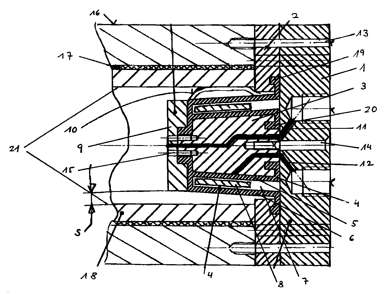
- 18 is a hollow wax core, whose circular opening 21 is to be sealed.
- the flexible sealing system has a metallic one Outer cover 1, the diameter of which is larger than that the opening 21 to be sealed is preferably circular is designed.
- the outer cover 1 closes a likewise metallic sealing ring 2, the outer edge of which aligned with the outer edge of the outer cover 1.
- the sealing ring 2 is, for example, with the outer cover 1 via a screw connection 13 connected.
- the core 3 is supported by an elastically deformable sealing body 4, preferably surrounded by a suitable silicone compound, the two spaced apart, one annular has enclosed space 7 forming outer walls 5, 6 and engages with play in the opening 21 to be sealed, that in the unloaded state of the sealing body 4 a gap s of about 1 mm between the front end of the sealing body 4 and the inner wall of the opening 21.
- a metallic deformable is now in the annular space 7
- a first compressed air duct is designated, which both The outer cover 1 and the core 3 and the inner cover 9 in such a way enforced that he was unsealed in the remaining Part of the opening 21 of the wax hollow body 18 opens, see above that this can be pressurized to so he soaked with the surrounding tubular resin Nestling braid 17 and this against a tool 16 press.
- a second compressed air channel is designated, the The outer cover 1 and the core 2 are penetrated and the one on the outside of the core 2 opens in such a way that the core 3 surrounding it Sealing body 4 is inflated.
- the two outer walls bulge 5, 6 of the sealing body 4 and simultaneously spread that metallic link band inserted into the annular space 7 8, so that a uniform contact surface of the outer wall 6 to the associated part of the inner wall of the opening 21 takes place as it is schematically designated 10.
- Seal body 4 denotes that between the sealing ring 2 and the Outer cover 1 are jammed.
- the sealing system shown has the advantage that the Hollow wax cores no longer turned out to size on the lathe have to be and that different inner diameters and thus sealing different wall thicknesses of the hollow wax core can be.
- the sealing system makes the elastic deformation of the wax hollow core and seals its opening reliably from.
- the setting values are reproducible at any time, the sealing system according to the invention being reusable, robust and reliable. is.
- a commercially available one is preferably used for the sealing body 4 Silicone used in the form of an uncrosslinked silicone matrix, with a hardener, for example a platinum catalyst, which initiates the polymerization, mixed becomes. If necessary, a stabilizer to increase mixed with the viscosity of the silicone.
Landscapes
- Engineering & Computer Science (AREA)
- Mechanical Engineering (AREA)
- Lining Or Joining Of Plastics Or The Like (AREA)
- Seal Device For Vehicle (AREA)
- Gasket Seals (AREA)
- Moulds For Moulding Plastics Or The Like (AREA)
Abstract
Das flexible Dichtsystem, insbesondere für Wachshohlkerne,
besteht aus einem metallischem Aussendeckel, einem Dichtring,
einem in die abzudichtende Öffnung einsetzbaren, konisch
zulaufenden im wesentlichen kreisförmigen metallischen Kern,
der von einem elastisch verformbaren Dichtkörper umgeben
wird, welcher zwei im Abstand voneinander angeordnete
Außenwände aufweist, die einen ringförmigen geschlossenen
Raum bilden, in den ein metallisches verformbares Gliederband
eingelegt wird. Es sind getrennte Druckluftkanäle vorgesehen,
um sowohl den Wachshohlkern mit einem Innendruck zu
beaufschlagen als auch um den Dichtkörper aufzublasen.
Description
Die vorliegende Erfindung betrifft ein flexibles Dichtsystem für mit einer kreisförmigen Öffnung versehene Hohlkörper, insbesondere Wachshohlkerne.The present invention relates to a flexible sealing system for hollow bodies provided with a circular opening, in particular Hollow wax cores.
Hohlkerne und insbesondere Wachshohlkerne werden oftmals bei der Herstellung von Hohlprofil-Bauteilen, z. B. aus Faserverbundkunststoffen eingesetzt, bei dem ein mit Kunststoff getränktes Faserhalbzeug auf einem durch Druck expandierbaren Wachshohlkern mit einem dem Hohlprofil-Bauteil entsprechenden Querschnitt durch Druckbeaufschlagung des Hohlkerns in einer Aussenform zu dem Hohlprofil-Bauteil verpresst und der Hohlkern aus dem Hohlprofil-Bauteil entfernt wird. So beschreibt die DE 39 23 416 ein derartiges Verfahren, wobei ein Hohlkern verwendet wird, der hermetisch abgeschlossen ist und entweder einen konstanten Querschnitt aufweist oder sich verjüngt; zum Expandieren wird die Hohlform auf eine hohe Temperatur erwärmt, so dass eine plastische Verformung auftritt. Nach dem Abkühlen des Hohlkerns und des Hohlprofil-Bauteils wird der Hohlkern entfernt.Hollow cores and especially hollow wax cores are often used the production of hollow profile components, e.g. B. from fiber composite plastics used, in which a soaked with plastic Semi-finished fiber on a pressure expandable Wax hollow core with a corresponding to the hollow profile component Cross section by pressurizing the hollow core in one External shape pressed to the hollow profile component and the hollow core is removed from the hollow profile component. This is how the DE describes it 39 23 416 such a method, wherein a hollow core is used that is hermetically sealed and either one has a constant cross-section or tapers; to expand the hollow mold is heated to a high temperature, so that a plastic deformation occurs. After cooling the The hollow core and the hollow profile component are removed.
Bei der Herstellung von Heckspoilern für Kraftfahrzeuge werden oftmals Wachskerne verwendet, die mit Glasfasermatten belegt werden, welche mit duromeren Kunststoffen getränkt sind, um anschliessend in einer Presse verpresst zu werden. Hierbei werden vorzugsweise flächige Hohlprofil-Bauteile aus Faserverbundkunststoffen hergestellt, da nur die zur Pressrichtung senkrechten Flächenabschnitte der Glasfasermatte verpresst werden, Flächenabschnitte, die in Pressrichtung verlaufen, aber praktisch nicht.In the manufacture of rear spoilers for motor vehicles often used wax cores, covered with fiberglass mats be soaked in thermosetting plastics in order to then to be pressed in a press. Here are preferably flat hollow profile components made of fiber composite plastics manufactured because only the direction of pressing vertical surface sections of the glass fiber mat pressed surface sections that run in the pressing direction, however practically not.
In der deutschen Patentanmeldung P 197 09 104 (= em 11988) wurde bereits ein Verfahren zur Herstellung von Hohlprofil-Bauteilen aus Faserverbundkunststoffen vorgeschlagen, bei dem ein duromerer Kunststoff verwendet wird, der beim Verpressen aushärtet, unter Verwendung eines Wachshohlkerns, der zur Entfernung aus dem Hohlprofil-Bauteil herausgeschmolzen wird.In German patent application P 197 09 104 (= em 11988) has already been a process for the production of hollow profile components proposed from fiber composite plastics, in which a thermosetting plastic is used, which is used for pressing hardens using a hollow wax core that is used for removal is melted out of the hollow profile component.
Mit diesem bekannten Verfahren lassen sich Hohlprofil-Bauteile aus Faserverbundkunststoffen für hochbelastete Strukturbauteile herstellen, insbesondere für hochbelastbare Strukturbauteile mit veränderlichem Querschnitt. Das mit dem duromeren Kunststoff getränkte Faserhalbzeug wird dabei auf einem Wachshohlkern in einem Formwerkzeug angeordnet, welches die Aussenform bildet. Der Wachshohlkern wird innen mit einem flüssigem oder gasförmigen Medium unter Druck gesetzt, wodurch er expandiert und damit das Faserhalbzeug komprimiert. Unter dem Druck des Wachshohlkerns und vorzugsweise unter Erwärmung erfolgt danach die Aushärtung des duromeren Kunststoffes, wonach der Wachshohlkern entfernt wird.With this known method, hollow profile components can be made of fiber composite plastics for highly stressed structural components manufacture, especially for heavy-duty structural components with variable cross-section. That with the thermoset plastic soaked semi-finished fiber is placed on a hollow wax core arranged in a mold, which the outer shape forms. The wax hollow core is covered with a liquid or pressurized gaseous medium, causing it to expand and thus compresses the semi-finished fiber. Under the pressure of Wax hollow core and preferably with heating takes place afterwards hardening of the thermoset plastic, after which the hollow wax core Will get removed.
Um nun einen derartigen Wachshohlkern innen mit Druck und insbesondere mit Druckluft zu beaufschlagen, muss die Zugangsöffnung zum Wachshohlkern, die üblicherweise kreisförmig ausgestaltet ist, durch ein Dichtsystem geschlossen werden, welches zum einen eine zuverlässige Abdichtung der Öffnung gewährleistet und zum anderen die Zufuhr von Druckluft zum Inneren des Wachshohlkerns ermöglicht.Now around such a hollow hollow core with pressure and in particular To pressurize with compressed air, the access opening to the hollow wax core, which is usually circular is to be closed by a sealing system which on the one hand, a reliable sealing of the opening is guaranteed and on the other hand the supply of compressed air to the inside of the Wax hollow core enables.
Aufgabe der vorliegenden Erfindung ist es, ein derartiges Dichtsystem für einen mit einer kreisförmigen Öffnung versehenen Hohlkörper, insbesondere einen Wachshohlkörper, zu schaffen, welcher sich aufgrund seiner flexiblen Ausgestaltung optimal an die sich verändernde Kontur der Öffnung anpasst, das einfach im Aufbau ist und den empfindlichen Wachshohlkern bei dessen Expansion nicht beschädigt.The object of the present invention is such Sealing system for one with a circular opening To create hollow bodies, in particular a wax hollow body, which is optimal due to its flexible design adapts to the changing contour of the opening, the is simple in construction and with the sensitive wax core its expansion is not damaged.
Die Lösung dieser Aufgabe erfolgt mit dem im kennzeichnenden
Teil des Anspruchs 1 angegebenen Merkmalen; eine vorteilhafte
Weiterbildung ist im Unteranspruch beschrieben.This problem is solved with the characterizing
Features specified in
Das erfindungsgemässe flexible Dichtsystem bietet den Vorteil einer flexiblen Abdichtung bei allen auftretenden Innendrucken im Wachshohlkern, da es dessen Expansion mitmacht, ohne dass zusätzliche Kräfte auf die Innenwand der Öffnung des Wachshohlkerns ausgeübt werden, wobei es höheren Drucken bis ca. 8 bar standhält und Durchmesserschwankungen des Wachshohlkerns im Bereich dessen Öffnung ausgleicht; auch nicht ausgedrehte Wachshohlkerne, d. h. solche mit einer geringfügig rauhen Oberflächenstruktur an der Innenwand der Öffnung, werden zuverlässig abgedichtet.The flexible sealing system according to the invention offers the advantage a flexible seal for all internal pressures that occur in the hollow wax core, since it takes part in its expansion without additional forces on the inner wall of the opening of the hollow wax core be exercised, whereby there are higher pressures up to approx. 8 bar withstands and fluctuations in diameter of the hollow wax core in the Area whose opening compensates; not even turned out Hollow wax cores, d. H. those with a slightly rough surface structure on the inner wall of the opening, will be reliable sealed.
Im folgenden wird die Erfindung anhand der Zeichnung näher erläutert, in der ein vorteilhaftes Ausführungsbeispiel schematisch im Schnitt dargestellt ist.In the following the invention with reference to the drawing explained in which an advantageous embodiment schematically is shown in section.
In der einzigen Figur ist mit 18 ein Wachshohlkern bezeichnet,
dessen kreisförmige Öffnung 21 abgedichtet werden soll. In the single figure, 18 is a hollow wax core,
whose
Zu diesem Zweck besitzt das flexible Dichtsystem einen metallischen
Aussendeckel 1, dessen Durchmesser grösser als derjenige
der abzudichtenden Öffnung 21 ist und der vorzugsweise kreisförmig
ausgestaltet ist. An den Aussendeckel 1 schliesst sich
ein ebenfalls metallischer Dichtring 2 an, dessen Aussenrand
mit dem Aussenrand des Aussendeckels 1 fluchtet. Der Dichtring
2 ist beispielsweise mit dem Aussendeckel 1 über eine Verschraubung
13 verbunden.For this purpose, the flexible sealing system has a metallic one
Mit 3 ist ein in die abzudichtende Öffnung 21 einsetzbarer
leicht konisch zulaufender kreisförmiger metallischer Kern
bezeichnet, der mit dem Aussendeckel 1 vorzugsweise über eine
Verschraubung 14 fest verbunden ist.With 3 is in the
Der Kern 3 wird von einem elastisch verformbaren Dichtkörper 4,
vorzugsweise aus einer geeigneten Silikonmasse, umgeben, der
zwei im Abstand voneinander angeordnete, einen ringförmigen
geschlossenen Raum 7 bildende Aussenwände 5, 6 aufweist und der
mit Spiel derart in die abzudichtende Öffnung 21 eingreift, das
im nicht beaufschlagtem Zustand des Dichtkörpers 4 ein Spalt s
von ca. 1 mm zwischen dem vorderen Ende des Dichtkörpers 4 und
der Innenwand der Öffnung 21 besteht.The
In den ringförmigen Raum 7 ist nun ein metallisches verformbares
Gliederband 8 eingesetzt, z. B. in Form eines metallischen
Uhrarmbandes, wobei die Einzelteile durch eine elastische Verbindung
miteinander derart verbunden sind, dass der Durchmesser
des Gliederbandes 8 variabel ist.A metallic deformable is now in the
Stirnseitig an den Kern 3 liegt ein mit ihm z. B. über eine
Verschraubung 15 verbundener Innendeckel 9 an, der auch den
stirnseitigen Anteil des Dichtkörpers 4 zumindest teilweise
einklemmt.On the face of the
Mit 9 ist ein erster Druckluftkanal bezeichnet, der sowohl den
Aussendeckel 1 als auch den Kern 3 und den Innendeckel 9 dergestalt
durchsetzt, dass er in dem verbleibenden nicht abgedichteten
Teil der Öffnung 21 des Wachshohlkörpers 18 mündet, so
dass dieser mit einem Innendruck beaufschlagt werden kann, um
ihn so an das ihn umgebende schlauchförmige mit Harz getränkte
Geflecht 17 anzuschmiegen und dieses gegen ein Werkzeug 16 zu
pressen.With 9 a first compressed air duct is designated, which both
The
Mit 12 ist ein zweiter Druckluftkanal bezeichnet, der den
Aussendeckel 1 und den Kern 2 durchsetzt und der an der Aussenseite
des Kerns 2 derart mündet, dass der den Kern 3 umgebende
Dichtkörper 4 aufgeblasen wird. Wird nun Druckluft durch den
Druckluftkanal 12 eingeblasen, so wölben sich die beiden Aussenwände
5, 6 des Dichtkörpers 4 und spreizen gleichzeitig das
in den ringförmigen Raum 7 eingelegte metallische Gliederband
8, so dass eine gleichmässige Anlegefläche der äusseren Aussenwand
6 an den zugehörigen Teil der Innenwand der Öffnung 21
erfolgt, wie es schematisch mit 10 bezeichnet ist.With 12 a second compressed air channel is designated, the
The
Mit 19, 20 sind diejenigen Enden der Aussenwände 5, 6 des
Dichtkörpers 4 bezeichnet, die zwischen dem Dichtring 2 und dem
Aussendeckel 1 eingeklemmt sind.With 19, 20 those ends of the
Das dargestellte Dichtsystem weist den Vorteil auf, dass die Wachshohlkerne nicht mehr auf der Drehbank massgenau ausgedreht werden müssen und dass unterschiedliche Innendurchmesser und damit verschiedene Wandstärken des Wachshohlkerns abgedichtet werden können. Das Dichtsystem macht die elastische Verformung des Wachshohlkernes mit und dichtet dessen Öffnung zuverlässig ab. Die Einstellwerte sind jederzeit wieder reproduzierbar, wobei das erfindungsgemässe Dichtsystem wieder verwendbar, robust und zuverlässig. ist.The sealing system shown has the advantage that the Hollow wax cores no longer turned out to size on the lathe have to be and that different inner diameters and thus sealing different wall thicknesses of the hollow wax core can be. The sealing system makes the elastic deformation of the wax hollow core and seals its opening reliably from. The setting values are reproducible at any time, the sealing system according to the invention being reusable, robust and reliable. is.
Bei einer Konizität des Kerns und des Dichtkörpers von ca. 5°
treten keinerlei Abdichtprobleme auf; durch das Einlegen eines
metallischen verformbaren Gliederbandes in den durch die
beiden Aussenwände des Dichtkörpers gebildeten ringförmigen
Raum wird eine flächige Auflage der äusseren Aussenwand 6 des
Dichtkörpers 4 an die Innenwand der Öffnung 18 gewährleistet.
Wird zusätzlich eine Kühlmöglichkeit für das Dichtsystem verwendet,
beispielsweise in Form einer Kühlschlange, die das
Dichtsystem umgibt und z. B. durch eine Pumpe mit Wasser gekühlt
wird, so ist es möglich, eine höhere Wachsfestigkeit zu
erzielen, d. h. dass der Wachshohlkern höher erwärmt werden
kann und gleichzeitig Risse vermieden werden.With a taper of the core and the sealing body of approx. 5 °
there are no sealing problems; by inserting one
metallic deformable link belt in the through the
two outer walls of the sealing body formed annular
Space becomes a flat support of the
Damit ist es möglich, den Wachshohlkern mit höheren Innendrücken, z.B. bis über 5bar, zu beaufschlagen ohne ihn zu beschädigen bei einer gleichzeitigen Steigerung der Aushärtetemperatur bis in den besonders elastischen Bereich des Wachskerns.This enables the hollow wax core to be pressed with higher internal pressures, e.g. up to over 5bar, to be applied without damaging it with a simultaneous increase in the curing temperature down to the particularly elastic range of the Wax core.
Für den Dichtkörper 4 wird vorzugsweise ein handelsübliches
Silikon verwendet in Form einer unvernetzten Silikongrundmasse,
die mit einem Härter, beispielsweise einem Platin-Katalysator,
der die Polymerisation initiiert, vermischt
wird. Gegebenenfalls kann noch ein Stabilisator zur Erhöhung
der Viskosität des Silikons beigemischt werden.A commercially available one is preferably used for the sealing
Claims (3)
Applications Claiming Priority (2)
| Application Number | Priority Date | Filing Date | Title |
|---|---|---|---|
| DE1997141615 DE19741615C1 (en) | 1997-09-20 | 1997-09-20 | Flexible sealing system |
| DE19741615 | 1997-09-20 |
Publications (2)
| Publication Number | Publication Date |
|---|---|
| EP0906818A2 true EP0906818A2 (en) | 1999-04-07 |
| EP0906818A3 EP0906818A3 (en) | 2000-05-31 |
Family
ID=7843110
Family Applications (1)
| Application Number | Title | Priority Date | Filing Date |
|---|---|---|---|
| EP98116520A Withdrawn EP0906818A3 (en) | 1997-09-20 | 1998-09-01 | Flexible sealing device |
Country Status (2)
| Country | Link |
|---|---|
| EP (1) | EP0906818A3 (en) |
| DE (1) | DE19741615C1 (en) |
Family Cites Families (5)
| Publication number | Priority date | Publication date | Assignee | Title |
|---|---|---|---|---|
| US3337222A (en) * | 1964-09-25 | 1967-08-22 | Watt V Smith | Quick acting submarine shaft seal |
| FR2454029A1 (en) * | 1979-04-11 | 1980-11-07 | Petroles Cie Francaise | INFLATABLE JOINT WITH LARGE TRAVEL |
| DE3427735C1 (en) * | 1984-07-27 | 1985-10-17 | Deta-Akkumulatorenwerk Gmbh, 3422 Bad Lauterberg | Test nozzle which can be introduced into a filling opening of an accumulator housing |
| DE3923416A1 (en) * | 1989-07-12 | 1991-01-24 | Mecron Med Prod Gmbh | METHOD FOR PRODUCING A BODY HAVING A HOLLOW PROFILE |
| DE3931775A1 (en) * | 1989-09-23 | 1991-04-04 | Mueller Umwelttechnik | Coating machine for interior of sewers - consists of cylinder drawn along in sewer and has outer inflated rubber sleeves with annular space fed with sealing material |
-
1997
- 1997-09-20 DE DE1997141615 patent/DE19741615C1/en not_active Expired - Fee Related
-
1998
- 1998-09-01 EP EP98116520A patent/EP0906818A3/en not_active Withdrawn
Also Published As
| Publication number | Publication date |
|---|---|
| DE19741615C1 (en) | 1999-04-08 |
| EP0906818A3 (en) | 2000-05-31 |
Similar Documents
| Publication | Publication Date | Title |
|---|---|---|
| DE60226336T2 (en) | PROCESS FOR INNER OVERPRESSURE OF OBJECTS AND OBJECTS MADE THEREFOR | |
| DE2725280A1 (en) | Pipe connection system for thin metal pipes - uses compressible sleeve with conical section and ring collars | |
| DE2806004B2 (en) | Process for the production of an elastic containment for hydrocarbons | |
| DE3405456C2 (en) | Connection of two components, in particular two plastic half-shells for the intake system of an internal combustion engine | |
| DE2406131A1 (en) | HIGH EXTENSIBLE CAVITY ELASTOMER BUSHING AND METHOD AND MEANS OF ASSEMBLING THEREOF | |
| DE3243365C2 (en) | Pinch fitting for hoses for pressurized fluids | |
| EP1279449B1 (en) | Method for connecting two objects | |
| DE19511970A1 (en) | Forming double=walled tubing for air ducting or car industry | |
| DE19544161C2 (en) | Press fitting for the production of an inseparable tight connection of pipes | |
| DE19916789C1 (en) | Seal between the surfaces of two machine units is an inflatable hose within an open groove flush at one surface which can be filled with a pressure medium to bear in a sealed fit against the other surface | |
| EP1249286A1 (en) | Method and device for forming of undercuttings when joining superimposed workpieces, in particular coated and/or varnished metal sheets | |
| DE4425984C2 (en) | Method for producing a hollow metal component with different cross sections in the longitudinal direction | |
| DE2719882A1 (en) | Coupling for metal transmission pipe - uses metallic sleeve with sealing rings compressed into pipe wall | |
| DE10048005B4 (en) | Device for connecting at least two flat, superimposed components | |
| DE3215883C2 (en) | Adapter block for use in fluid technology | |
| DE19741615C1 (en) | Flexible sealing system | |
| EP3115171A1 (en) | Foaming mould with extendable sealing end piece | |
| DE19634219C2 (en) | Articulated vehicle with bellows, as well as procedures for assembling and disassembling the bellows | |
| DE19837131C2 (en) | Process for hydroforming two or more hollow bodies, each with at least one opening, in particular metal pipes or hollow metal profiles, and hydroforming machine for carrying out the process | |
| DE3840939A1 (en) | Method for the production of flat components | |
| DE102021102932B3 (en) | Hydraulic control unit having an intermediate plate with a partially solidified coating | |
| DE202006004457U1 (en) | Structure-O-Ring | |
| DE2819017A1 (en) | PROCESS FOR INJECTING A METALLIC BODY, IN PARTICULAR A HOLLOW BODY, INTO A PLASTIC BODY | |
| DE3314907C2 (en) | Method for producing a flexible rubber hose with connections | |
| DE102005006204B4 (en) | gasket |
Legal Events
| Date | Code | Title | Description |
|---|---|---|---|
| PUAI | Public reference made under article 153(3) epc to a published international application that has entered the european phase |
Free format text: ORIGINAL CODE: 0009012 |
|
| AK | Designated contracting states |
Kind code of ref document: A2 Designated state(s): DE ES FR GB IT |
|
| AX | Request for extension of the european patent |
Free format text: AL;LT;LV;MK;RO;SI |
|
| PUAL | Search report despatched |
Free format text: ORIGINAL CODE: 0009013 |
|
| RIC1 | Information provided on ipc code assigned before grant |
Free format text: 7B 29C 33/72 A, 7B 29C 53/82 B, 7F 16J 15/46 B |
|
| AK | Designated contracting states |
Kind code of ref document: A3 Designated state(s): AT BE CH CY DE DK ES FI FR GB GR IE IT LI LU MC NL PT SE |
|
| AX | Request for extension of the european patent |
Free format text: AL;LT;LV;MK;RO;SI |
|
| 17P | Request for examination filed |
Effective date: 20001123 |
|
| AKX | Designation fees paid |
Free format text: DE ES FR GB IT |
|
| GRAG | Despatch of communication of intention to grant |
Free format text: ORIGINAL CODE: EPIDOS AGRA |
|
| 17Q | First examination report despatched |
Effective date: 20011207 |
|
| STAA | Information on the status of an ep patent application or granted ep patent |
Free format text: STATUS: THE APPLICATION IS DEEMED TO BE WITHDRAWN |
|
| 18D | Application deemed to be withdrawn |
Effective date: 20020403 |