EP0906772A2 - Fire curtain - Google Patents
Fire curtain Download PDFInfo
- Publication number
- EP0906772A2 EP0906772A2 EP98203330A EP98203330A EP0906772A2 EP 0906772 A2 EP0906772 A2 EP 0906772A2 EP 98203330 A EP98203330 A EP 98203330A EP 98203330 A EP98203330 A EP 98203330A EP 0906772 A2 EP0906772 A2 EP 0906772A2
- Authority
- EP
- European Patent Office
- Prior art keywords
- curtain
- ceiling
- opening
- outer member
- emergency
- Prior art date
- Legal status (The legal status is an assumption and is not a legal conclusion. Google has not performed a legal analysis and makes no representation as to the accuracy of the status listed.)
- Granted
Links
Images

Classifications
-
- A—HUMAN NECESSITIES
- A62—LIFE-SAVING; FIRE-FIGHTING
- A62C—FIRE-FIGHTING
- A62C2/00—Fire prevention or containment
- A62C2/06—Physical fire-barriers
- A62C2/10—Fire-proof curtains
Definitions
- the present invention relates to an emergency curtain, in particularly a fire curtain.
- fire curtain is used to indicate any curtain intended to contain or at least retard not only fire as such but any effect or combustion product of fire, such as smoke.
- Fire curtains are installed in premises, such as shops, for dividing the interior of the premises in the event of a fire to slow the spread of smoke and the fire.
- they are installed in ceilings and are deployed by unrolling down from an opening in the ceiling.
- the opening is an elongate gap or slot in the ceiling.
- the latter may be a conventional ceiling attached to joists or a suspended ceiling lower than the joists or other structural members, the opening being between boards, panels or like member comprising the ceiling. Closing the opening in the ceiling can be aesthetically difficult.
- the object of the invention is to provide a curtain having an improved ceiling aperture closure of a ceiling opening.
- An emergency curtain of the invention for installation at a ceiling opening comprises:
- the outer member is conveniently of a section and material to be flexible for following ceiling undulations.
- the outer member should engage the ceiling internally of the opening, with the member fitting within the opening; preferably, the outer member is wider than the opening and engages the underside of the ceiling.
- the resilient means comprises a series of spring connections between the inner and outer members.
- the springs are arranged longitudinally of the outer member with flexible connections turning their line of action upwards the to inner member.
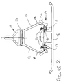
- the curtain 1 shown in the drawings comprises a conventional pair of curtain rolls 2,3 - for a double skin curtain - mounted in a housing 4 suspending from a ceiling structural member 5 above an opening 6 in the ceiling 7.
- a winding mechanism (not shown) is arranged at one end of the housing for driving and stopping the rolls to raise or lower the curtain fabric 8 rolled on the rolls as required.
- a bottom bar 9 is attached to the bottom edge of the curtain fabric.
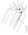
- the bottom bar has an inner member 11 formed of two identical members 12,13 fastened by screws 14 back-to-back with the fabric 8 clamped between.
- the inner member is of a width to drop through the opening 6. Beneath the inner member, a wider outer member 15 is arranged. It is wider than the opening, so that when drawn against the ceiling, it obscures the edges of the ceiling at the opening.
- the outer member is connected to the inner member by wires 16 and springs 17.
- the inner member has upwardly divergent lower sides 18.
- the outer member is essentially flat, with low flanges 19 extending up from its top surface.
- the flanges have upwardly divergent lips 20, which engage the lower sides 18 for centring of the inner and outer members when they are in contact as shown in Figure 2.
- the members are held slightly apart by plastics material eyelets 21 pressed into horizontal portions of the flanges 19.
- the wires 16 pass through apertures 22 in the inner member above the eyelets and terminate above them. Below the eyelets, or at least each pair of them, the wires turn in pairs towards each other and are fixed to opposite ends of the springs 17. Thus tension in the springs urges the outer member up towards the inner member.
- the wires and spring tension are sized to be able to lift the outer member. They are of stainless steel, the wires being nylon covered.
- the outer member has little vertical height, whereby even when extruded in aluminium it is flexible for vertical deflection.
- the outer member can flex to accommodate undulations in the ceiling level.
- the springs are strong enough in their extended, use state to flex the outer member. This is the normal use position.
- the inner member of the bottom bar drops through the opening in the ceiling and the springs draw the outer member up against the inner member.
Landscapes
- Health & Medical Sciences (AREA)
- Public Health (AREA)
- Business, Economics & Management (AREA)
- Emergency Management (AREA)
- Curtains And Furnishings For Windows Or Doors (AREA)
- Operating, Guiding And Securing Of Roll- Type Closing Members (AREA)
Abstract
Description
Claims (7)
- An emergency curtain (1) for installation at a ceiling opening (6), the curtain comprising a curtain winding mechanism, a curtain roll (2), (3) connected to the winding mechanism, curtain fabric (8) wound on the roll (2), (3) and a bottom bar (9) attached to the bottom edge of the curtain fabric; characterised in that the bottom bar (9) includes:an inner member (11) secured to the fabric (8) as such;an outer member (15) adapted to engage the ceiling (7) at the opening (6) and close it; andresilient means (16), (17) connecting the inner member (11) and the outer member (15) for drawing the outer member (15) to the ceiling opening (6), when the curtain is wound up.
- An emergency curtain as claimed in claim 1, characterised in that the outer member (15) is of a section and material such that the member is flexible for following ceiling undulations.
- An emergency curtain as claimed in claim 1 or claim 2, characterised in that the outer member (15) is adapted to engage the ceiling (7) internally of the opening (6), with the member (15) engaging within the opening (6).
- An emergency curtain as claimed in claim 1 or claim 2, characterised in that the outer member (15) is wider than the opening (6) for engaging the underside of the ceiling (7).
- An emergency curtain as claimed in any preceding claim, wherein the resilient means comprises a series of spring (17) connections between the inner (11) and outer (15) members.
- An emergency curtain as claimed in claim 5, characterised in that the springs (17) are arranged longitudinally of the outer member (15) with flexible connections (16) turning their line of action upwards to the inner member (11).
- An emergency curtain as claimed in any preceding claim, characterised in that the inner member (11) has upwardly divergent lower sides (18), and the outer member (15) has low flanges (19) extending up from its top surface, the flanges having upwardly divergent lips (20) for engagement with the lower sides (18) of the inner members (11) for centring of the inner (11) and outer (15) members when in contact.
Applications Claiming Priority (2)
| Application Number | Priority Date | Filing Date | Title |
|---|---|---|---|
| GB9721054A GB2329835B (en) | 1997-10-04 | 1997-10-04 | Curtain |
| GB9721054 | 1997-10-04 |
Publications (3)
| Publication Number | Publication Date |
|---|---|
| EP0906772A2 true EP0906772A2 (en) | 1999-04-07 |
| EP0906772A3 EP0906772A3 (en) | 2001-03-28 |
| EP0906772B1 EP0906772B1 (en) | 2005-08-03 |
Family
ID=10820038
Family Applications (1)
| Application Number | Title | Priority Date | Filing Date |
|---|---|---|---|
| EP19980203330 Expired - Lifetime EP0906772B1 (en) | 1997-10-04 | 1998-10-01 | Fire curtain |
Country Status (3)
| Country | Link |
|---|---|
| EP (1) | EP0906772B1 (en) |
| DE (1) | DE69831044T2 (en) |
| GB (1) | GB2329835B (en) |
Cited By (2)
| Publication number | Priority date | Publication date | Assignee | Title |
|---|---|---|---|---|
| DE102011012657B3 (en) * | 2011-02-28 | 2012-05-31 | Stöbich Brandschutz GmbH | Fire or smoke protection curtain for closing a building opening and associated method |
| RU189156U1 (en) * | 2017-10-19 | 2019-05-15 | Роман Олегович Русских | FIRE FIGHTING |
Families Citing this family (2)
| Publication number | Priority date | Publication date | Assignee | Title |
|---|---|---|---|---|
| SG109406A1 (en) * | 1999-06-03 | 2005-03-30 | Andrew Paul Cooper | Curtain |
| DE102015117548B4 (en) | 2015-10-15 | 2023-12-14 | Kgg Brandschutzsysteme Gmbh | Closure device and method for assembling a closure device for a building opening |
Family Cites Families (3)
| Publication number | Priority date | Publication date | Assignee | Title |
|---|---|---|---|---|
| GB2108839B (en) * | 1981-10-13 | 1985-09-04 | Andrew Paul Cooper | Fire screens or curtains |
| GB2299021B (en) * | 1995-03-22 | 1999-08-25 | Rasontec Nv | Curtain,end bar and guide bar |
| JP3574956B2 (en) * | 1996-05-30 | 2004-10-06 | 三和シヤッター工業株式会社 | Twin fire shutter |
-
1997
- 1997-10-04 GB GB9721054A patent/GB2329835B/en not_active Expired - Fee Related
-
1998
- 1998-10-01 EP EP19980203330 patent/EP0906772B1/en not_active Expired - Lifetime
- 1998-10-01 DE DE69831044T patent/DE69831044T2/en not_active Expired - Lifetime
Cited By (4)
| Publication number | Priority date | Publication date | Assignee | Title |
|---|---|---|---|---|
| DE102011012657B3 (en) * | 2011-02-28 | 2012-05-31 | Stöbich Brandschutz GmbH | Fire or smoke protection curtain for closing a building opening and associated method |
| EP2491982A2 (en) | 2011-02-28 | 2012-08-29 | Stöbich Brandschutz GmbH | Fire or smoke retardant curtain for closing a building opening and associated method |
| EP2491982A3 (en) * | 2011-02-28 | 2013-08-14 | Stöbich Brandschutz GmbH | Fire or smoke retardant curtain for closing a building opening and associated method |
| RU189156U1 (en) * | 2017-10-19 | 2019-05-15 | Роман Олегович Русских | FIRE FIGHTING |
Also Published As
| Publication number | Publication date |
|---|---|
| GB2329835B (en) | 2000-11-15 |
| DE69831044D1 (en) | 2005-09-08 |
| HK1018017A1 (en) | 1999-12-10 |
| GB2329835A (en) | 1999-04-07 |
| GB9721054D0 (en) | 1997-12-03 |
| DE69831044T2 (en) | 2006-04-06 |
| EP0906772A3 (en) | 2001-03-28 |
| EP0906772B1 (en) | 2005-08-03 |
Similar Documents
| Publication | Publication Date | Title |
|---|---|---|
| US3900063A (en) | Roller curtain | |
| US4884617A (en) | Roll-up shutter structure | |
| CN1115464C (en) | Roller shutter door with low friction edge | |
| US5445209A (en) | Guide system for vertically moveable flexible door | |
| EP3105401B1 (en) | Fast roll-up door comprising a curtain having resilient edges | |
| US7293393B2 (en) | Perimeter clip for seismic ceilings | |
| US5765622A (en) | Vertically moveable flexible door with releasable bottom bar | |
| CA2342564C (en) | Track concealing system for operable walls | |
| US4126174A (en) | Flexible sheet rollup window structure | |
| EP0906772B1 (en) | Fire curtain | |
| US20180298687A1 (en) | Track System for Retractable Wall | |
| US7165688B2 (en) | Retractable hanging apparatus | |
| NL1035926C2 (en) | Screen device. | |
| US4298048A (en) | Roll-up divider | |
| CA2104416C (en) | Flexible partition | |
| KR102145069B1 (en) | Guiding apparatus for making pleat of curtain | |
| JPS59213883A (en) | Wind resistant wind-up shutter | |
| CA3013605A1 (en) | Roller blind end bracket with retaining member | |
| EP0370550A1 (en) | Roll up door | |
| JP3295764B2 (en) | Winding structure of ceiling-mounted smoke-proof banner | |
| EP0550619A1 (en) | CURTAIN DEVICE. | |
| JPS6341008Y2 (en) | ||
| AU2015101228A4 (en) | Roller Door Track | |
| US5890528A (en) | Roll-up blind and cord guide unit | |
| JP2769362B2 (en) | Amai |
Legal Events
| Date | Code | Title | Description |
|---|---|---|---|
| PUAI | Public reference made under article 153(3) epc to a published international application that has entered the european phase |
Free format text: ORIGINAL CODE: 0009012 |
|
| AK | Designated contracting states |
Kind code of ref document: A2 Designated state(s): BE DE ES FR GB IE NL |
|
| AX | Request for extension of the european patent |
Free format text: AL;LT;LV;MK;RO;SI |
|
| PUAL | Search report despatched |
Free format text: ORIGINAL CODE: 0009013 |
|
| AK | Designated contracting states |
Kind code of ref document: A3 Designated state(s): AT BE CH CY DE DK ES FI FR GB GR IE IT LI LU MC NL PT SE |
|
| AX | Request for extension of the european patent |
Free format text: AL;LT;LV;MK;RO;SI |
|
| 17P | Request for examination filed |
Effective date: 20010629 |
|
| AKX | Designation fees paid |
Free format text: BE DE ES FR GB IE NL |
|
| GRAP | Despatch of communication of intention to grant a patent |
Free format text: ORIGINAL CODE: EPIDOSNIGR1 |
|
| GRAS | Grant fee paid |
Free format text: ORIGINAL CODE: EPIDOSNIGR3 |
|
| GRAA | (expected) grant |
Free format text: ORIGINAL CODE: 0009210 |
|
| AK | Designated contracting states |
Kind code of ref document: B1 Designated state(s): BE DE ES FR GB IE NL |
|
| PG25 | Lapsed in a contracting state [announced via postgrant information from national office to epo] |
Ref country code: NL Free format text: LAPSE BECAUSE OF FAILURE TO SUBMIT A TRANSLATION OF THE DESCRIPTION OR TO PAY THE FEE WITHIN THE PRESCRIBED TIME-LIMIT Effective date: 20050803 Ref country code: BE Free format text: LAPSE BECAUSE OF FAILURE TO SUBMIT A TRANSLATION OF THE DESCRIPTION OR TO PAY THE FEE WITHIN THE PRESCRIBED TIME-LIMIT Effective date: 20050803 |
|
| REG | Reference to a national code |
Ref country code: GB Ref legal event code: FG4D |
|
| REG | Reference to a national code |
Ref country code: IE Ref legal event code: FG4D |
|
| REF | Corresponds to: |
Ref document number: 69831044 Country of ref document: DE Date of ref document: 20050908 Kind code of ref document: P |
|
| PG25 | Lapsed in a contracting state [announced via postgrant information from national office to epo] |
Ref country code: IE Free format text: LAPSE BECAUSE OF NON-PAYMENT OF DUE FEES Effective date: 20051003 |
|
| PG25 | Lapsed in a contracting state [announced via postgrant information from national office to epo] |
Ref country code: GB Free format text: LAPSE BECAUSE OF NON-PAYMENT OF DUE FEES Effective date: 20051103 |
|
| PG25 | Lapsed in a contracting state [announced via postgrant information from national office to epo] |
Ref country code: ES Free format text: LAPSE BECAUSE OF FAILURE TO SUBMIT A TRANSLATION OF THE DESCRIPTION OR TO PAY THE FEE WITHIN THE PRESCRIBED TIME-LIMIT Effective date: 20051114 |
|
| NLV1 | Nl: lapsed or annulled due to failure to fulfill the requirements of art. 29p and 29m of the patents act | ||
| ET | Fr: translation filed | ||
| PLBE | No opposition filed within time limit |
Free format text: ORIGINAL CODE: 0009261 |
|
| STAA | Information on the status of an ep patent application or granted ep patent |
Free format text: STATUS: NO OPPOSITION FILED WITHIN TIME LIMIT |
|
| 26N | No opposition filed |
Effective date: 20060504 |
|
| GBPC | Gb: european patent ceased through non-payment of renewal fee |
Effective date: 20051103 |
|
| REG | Reference to a national code |
Ref country code: IE Ref legal event code: MM4A |
|
| REG | Reference to a national code |
Ref country code: FR Ref legal event code: ST Effective date: 20150630 |
|
| PG25 | Lapsed in a contracting state [announced via postgrant information from national office to epo] |
Ref country code: FR Free format text: LAPSE BECAUSE OF NON-PAYMENT OF DUE FEES Effective date: 20141031 |
|
| REG | Reference to a national code |
Ref country code: FR Ref legal event code: RN Effective date: 20150910 |
|
| REG | Reference to a national code |
Ref country code: FR Ref legal event code: FC Effective date: 20150930 |
|
| REG | Reference to a national code |
Ref country code: FR Ref legal event code: PLFP Year of fee payment: 18 |
|
| PGFP | Annual fee paid to national office [announced via postgrant information from national office to epo] |
Ref country code: DE Payment date: 20151016 Year of fee payment: 18 |
|
| PGFP | Annual fee paid to national office [announced via postgrant information from national office to epo] |
Ref country code: FR Payment date: 20151103 Year of fee payment: 18 |
|
| PGRI | Patent reinstated in contracting state [announced from national office to epo] |
Ref country code: FR Effective date: 20150930 |
|
| REG | Reference to a national code |
Ref country code: DE Ref legal event code: R119 Ref document number: 69831044 Country of ref document: DE |
|
| REG | Reference to a national code |
Ref country code: FR Ref legal event code: ST Effective date: 20170630 |
|
| PG25 | Lapsed in a contracting state [announced via postgrant information from national office to epo] |
Ref country code: FR Free format text: LAPSE BECAUSE OF NON-PAYMENT OF DUE FEES Effective date: 20161102 Ref country code: DE Free format text: LAPSE BECAUSE OF NON-PAYMENT OF DUE FEES Effective date: 20170503 |