EP0906579B1 - Sensor device for the 3-dimensional measurement of an attitude or acceleration - Google Patents
Sensor device for the 3-dimensional measurement of an attitude or acceleration Download PDFInfo
- Publication number
- EP0906579B1 EP0906579B1 EP97927215A EP97927215A EP0906579B1 EP 0906579 B1 EP0906579 B1 EP 0906579B1 EP 97927215 A EP97927215 A EP 97927215A EP 97927215 A EP97927215 A EP 97927215A EP 0906579 B1 EP0906579 B1 EP 0906579B1
- Authority
- EP
- European Patent Office
- Prior art keywords
- sensor
- cavity
- measuring
- acceleration
- sensors
- Prior art date
- Legal status (The legal status is an assumption and is not a legal conclusion. Google has not performed a legal analysis and makes no representation as to the accuracy of the status listed.)
- Expired - Lifetime
Links
- 230000001133 acceleration Effects 0.000 title claims abstract description 20
- 238000005259 measurement Methods 0.000 title 1
- 239000012530 fluid Substances 0.000 claims abstract description 18
- 239000000126 substance Substances 0.000 claims abstract description 14
- 239000000463 material Substances 0.000 claims abstract description 6
- 238000010276 construction Methods 0.000 description 2
- 230000003287 optical effect Effects 0.000 description 2
- 239000000084 colloidal system Substances 0.000 description 1
- 238000010586 diagram Methods 0.000 description 1
- 230000005684 electric field Effects 0.000 description 1
- 239000007789 gas Substances 0.000 description 1
- 239000000499 gel Substances 0.000 description 1
- 230000010354 integration Effects 0.000 description 1
- 239000007788 liquid Substances 0.000 description 1
- 238000004519 manufacturing process Methods 0.000 description 1
- 239000012528 membrane Substances 0.000 description 1
- 230000007935 neutral effect Effects 0.000 description 1
- 230000035515 penetration Effects 0.000 description 1
- 229920003023 plastic Polymers 0.000 description 1
- 239000004033 plastic Substances 0.000 description 1
- 230000010287 polarization Effects 0.000 description 1
Images
Classifications
-
- G—PHYSICS
- G01—MEASURING; TESTING
- G01C—MEASURING DISTANCES, LEVELS OR BEARINGS; SURVEYING; NAVIGATION; GYROSCOPIC INSTRUMENTS; PHOTOGRAMMETRY OR VIDEOGRAMMETRY
- G01C9/00—Measuring inclination, e.g. by clinometers, by levels
- G01C9/18—Measuring inclination, e.g. by clinometers, by levels by using liquids
-
- G—PHYSICS
- G01—MEASURING; TESTING
- G01P—MEASURING LINEAR OR ANGULAR SPEED, ACCELERATION, DECELERATION, OR SHOCK; INDICATING PRESENCE, ABSENCE, OR DIRECTION, OF MOVEMENT
- G01P15/00—Measuring acceleration; Measuring deceleration; Measuring shock, i.e. sudden change of acceleration
- G01P15/006—Measuring acceleration; Measuring deceleration; Measuring shock, i.e. sudden change of acceleration by making use of fluid seismic masses
-
- G—PHYSICS
- G01—MEASURING; TESTING
- G01P—MEASURING LINEAR OR ANGULAR SPEED, ACCELERATION, DECELERATION, OR SHOCK; INDICATING PRESENCE, ABSENCE, OR DIRECTION, OF MOVEMENT
- G01P15/00—Measuring acceleration; Measuring deceleration; Measuring shock, i.e. sudden change of acceleration
- G01P15/18—Measuring acceleration; Measuring deceleration; Measuring shock, i.e. sudden change of acceleration in two or more dimensions
Definitions
- the present invention relates to a sensor device for measuring an attitude, acceleration or gravitational field and its gradient components, said device including a spherical cavity which contains a sensor substance in the form of a fluid or some other inertial material having fluidic properties.
- An accelerometer provided with a spherical cavity is prior known e.g. from Patent publication US 3461730.
- This prior known device produces an absolute acceleration value regardless of direction.
- a device of the invention can be used for sensoring an acceleration as a vector quantity.
- the prior known device include any indications for identifying the attitude of the device, while one of the fundamental features of the present invention is the identification of an attitude of the device.
- a sensor device for measuring a vertical component of the acceleration using a fluid filling a cavity is known from EP 0 460 789 A1.
- the sensors may comprise piezoelectric transducers, capacitive membrane sensors and elongation strip sensors. Other types of sensors or transducers can also be used, as described in more detail hereinafter.
- An object of the invention is to provide a sensor device, capable of determining the attitude of the device or the rate and direction of its acceleration 3-dimensionally.
- the sensor device must have an equal directionality in all directions to make it capable of sensoring an acceleration vector, in addition to which the device also serves as an attitude identifier.
- Some of the application areas for a sensor device of the invention are e.g. as follows:
- a spherical container 3 contains a fluid at a pressure Po.
- the container 3 is provided with imaginary rectangular coordinates x, y, z, whose positive axial directions intersect the spherical surface at points P 1 , P 3 and P 5 and negative axial directions at points P 2 , P 4 and P 6 , respectively.
- At least the points P are provided with sensors (measuring sensors or electrodes), which sample some material property of the sensor fluid as a function of the fluid pressure.
- This pressure is 0 at the point where the direction of an acceleration vector extending through the centre of the spherical surface intersects said spherical surface and the maximum pressure value according to formula (1) is found at the intersection of the opposite vector direction and the spherical surface.
- the pressure is determined in each case according to individual measuring points and then by applying the formulae according to equation groups (2) and (3).
- Fig. 4 depicts one example of a measuring circuit design in the case of a passive sensor.
- a piezo sensor 4 or other pressure responsive sensor is placed at a measuring point P n .
- a preamplifier 5 amplifies a sensor signal, which is fed by way of a signal adapter 6 to an A/D converter 7.
- the digital signals received from various sensors are fed to a computer 8, which performs the necessary calculations in accordance with the above formulae.
- Fig. 3 illustrates a sensor unit which comprises a cubic-shaped body, which is assembled from separate pieces 1, 2 on the opposite sides of a division plane 9 with the halves of a spherical cavity 3 machined and the sensors fitted therein prior to joining the cubic halves together.
- the sensor material filling the cavity 3 comprises a fluid, liquid or gas or some other substance with fluidic properties, such as gels or colloids. If the sensor fluid to be used is electrically or optically neutral relative to pressure, the pressure is measured directly by means of a sensor (passive or active) integrated in the system.
- a sensor passive or active
- An essential feature in the invention is that the sensor fluid is common to all sensors performing 3-dimensional measuring. The sensors may respond to changes in the pressure of a sensor fluid, e.g. with one of the following results:
- Sensor substances which have electrical or optical responses as a result of pressure existing in the substance, may respond to pressure variations caused by acceleration, e.g. with one of the following results:
- the sensor substance within the cavity may be an integral part of measuring sensors.
- the mere electrodes on the surface of a cavity are adapted to measure changes occurring in the sensor substance.
- a sensor device of the invention is characterized in that the construction measuring 3-dimensionally its attitude or acceleration has been created as a compact unit having a high degree of integration. At the moment, such an achievement requires the arrangement of three separate sensor devices whose assemblage involves both mechanical problems and problems relating to the processing of results. These problems have been resolved by means of a sensor device of the invention.
- the sensor device is capable of measuring the attitude of its base which is at rest or in constant motion. In case the sensor device is in accelerating motion and it is desirable to measure acceleration of the motion as a vector quantity, the gravitational acceleration and the attitude must be known or brought into the system from an external source. If it is desirable to measure an attitude while the sensor device is in accelerating motion, the acceleration of the motion must be known or brought into the system from external sources.
- the present invention can be used also for measuring all of the gradient components of the gravitational field, in case the pressure sensoring locations are added as necessary.
Landscapes
- General Physics & Mathematics (AREA)
- Physics & Mathematics (AREA)
- Engineering & Computer Science (AREA)
- Radar, Positioning & Navigation (AREA)
- Remote Sensing (AREA)
- Measuring Fluid Pressure (AREA)
- Measurement Of Length, Angles, Or The Like Using Electric Or Magnetic Means (AREA)
- Length Measuring Devices With Unspecified Measuring Means (AREA)
- Gyroscopes (AREA)
- Force Measurement Appropriate To Specific Purposes (AREA)
- Vehicle Body Suspensions (AREA)
- Testing Or Calibration Of Command Recording Devices (AREA)
- Control Of Position Or Direction (AREA)
- Body Structure For Vehicles (AREA)
- Transmission And Conversion Of Sensor Element Output (AREA)
- Analysing Materials By The Use Of Radiation (AREA)
- Position Input By Displaying (AREA)
- Length Measuring Devices By Optical Means (AREA)
Abstract
Description
- The present invention relates to a sensor device for measuring an attitude, acceleration or gravitational field and its gradient components, said device including a spherical cavity which contains a sensor substance in the form of a fluid or some other inertial material having fluidic properties.
- An accelerometer provided with a spherical cavity is prior known e.g. from Patent publication US 3461730. This prior known device produces an absolute acceleration value regardless of direction. Unlike this, a device of the invention can be used for sensoring an acceleration as a vector quantity. Neither does the prior known device include any indications for identifying the attitude of the device, while one of the fundamental features of the present invention is the identification of an attitude of the device.
- A sensor device for measuring a vertical component of the acceleration using a fluid filling a cavity is known from
EP 0 460 789 A1. - As for the prior art, reference can also be made to publications US 3992951 and EP 0566130. The latter relates to a sensor for rotational motion, describing the principles of sensor elements or transducers which can be applied also in the present invention. In other words, the sensors may comprise piezoelectric transducers, capacitive membrane sensors and elongation strip sensors. Other types of sensors or transducers can also be used, as described in more detail hereinafter.
- An object of the invention is to provide a sensor device, capable of determining the attitude of the device or the rate and direction of its acceleration 3-dimensionally. In other words, the sensor device must have an equal directionality in all directions to make it capable of sensoring an acceleration vector, in addition to which the device also serves as an attitude identifier.
- This object is achieved by means of the invention on the basis of the characterizing features set forth in the annexed claims.
- Some of the application areas for a sensor device of the invention are e.g. as follows:
- in industrial manufacturing and robotics as attitude identifier or a triaxial sensor for linear motion (acceleration)
- in navigation systems (inertial navigation) in land vehicles, water- and aircraft, in various self-controlled or self-navigated mobile devices
- in so-called black boxes of vehicles (when the kinetic history of a vehicle is to be recorded)
- in geophysics, geotechnique and in other areas of construction engineering e.g. as a triaxial vibration transducer, as an attitude sensor in drill holes, as a motion/attitude sensor for equipment towed by survey vessels, and as a sensor for gravitational field measuring equipment.
- The invention will now be described in more detail with reference made to the accompanying drawings, in which
- fig. 1
- shows a spherical cavity in a measuring sensor with its 3-D coordinate axes;
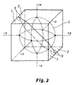
- fig. 2
- shows the same cavity, having its inertial fluid
subjected to the action of a vector force
F ; - fig. 3
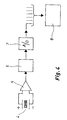
- shows one structural design for a sensor unit in a sensor device of the invention according to one exemplary embodiment; and
- fig. 4
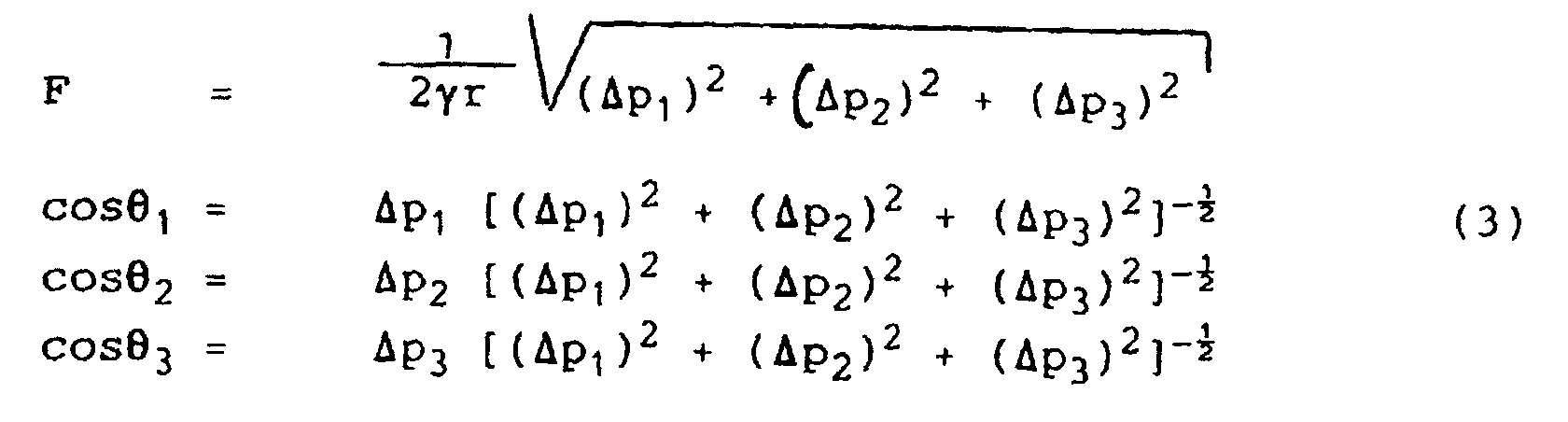
- is a block diagram, showing an example of a measuring circuit design for a sensor device.
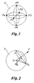
- First explained is the theoretical background of the invention with reference to figs. 1 and 2. In the arrangement of fig. 1, a
spherical container 3 contains a fluid at a pressure Po. Thecontainer 3 is provided with imaginary rectangular coordinates x, y, z, whose positive axial directions intersect the spherical surface at points P1, P3 and P5 and negative axial directions at points P2, P4 and P6, respectively. - At least the points P are provided with sensors (measuring sensors or electrodes), which sample some material property of the sensor fluid as a function of the fluid pressure.
- If a body, which contains the
fluid container 3, travels at an accelerationF , the fluid within the container, as a result of inertia, develops a pressure whose magnitude at its maximum is - This pressure is 0 at the point where the direction of an acceleration vector extending through the centre of the spherical surface intersects said spherical surface and the maximum pressure value according to formula (1) is found at the intersection of the opposite vector direction and the spherical surface.
- If T is a normal plane for the vector
F , extending through a point Pn (n = 1...6), it can be concluded on the basis of fig. 2 that: - the distance between the plane T and the centre of the
spherical surface is
- the distance of the plane T from a point, at which the inertia-induced fluid pressure = 0, is r(1 - cosn)
- at the point Pn prevails a pressure pn = γr (1 - cosn) F
- pressure Pn+1 = γr (1 + cosn) F for n = 1,3.5 since cos ( + π) = -cos
- In the above formulae and in fig. 2
OPn = rq n°
r = radius
q n° = unit vector
F ° = unit vector in the direction ofF
n = intervectorial angle
If, according to the starting premise, the fluid is further thought to have a pressure po, the points Pn and Pn+1 can be measured to have pressures (pn + po) and (pn+1 + po). - When Δpn = (pn + po) - (pn+1 + po) = Pn - pn+1 = 2γrFcosn

- On the basis of this (Δp1)2 + (Δp2)2 + (Δp3)2 = (2γFr)2 (cos21 + cos22 + cos23) which has a consequence thatthe rate and direction of the acceleration vector
F relative to the system axes is thus determined. In the simplest case, the relationship between a signal and pressure to be measured at points Pn is linear. Signal = k x pressure.
- In cases other than the simple relationships shown in the above formulae, the pressure is determined in each case according to individual measuring points and then by applying the formulae according to equation groups (2) and (3).
- In order to determine the pressure from measured signals, it is possible to use a computer or other microprocessor-controlled calculating circuits.
- Fig. 4 depicts one example of a measuring circuit design in the case of a passive sensor. A piezo sensor 4 or other pressure responsive sensor is placed at a measuring point Pn. A preamplifier 5 amplifies a sensor signal, which is fed by way of a
signal adapter 6 to an A/D converter 7. The digital signals received from various sensors are fed to acomputer 8, which performs the necessary calculations in accordance with the above formulae. - Fig. 3 illustrates a sensor unit which comprises a cubic-shaped body, which is assembled from
separate pieces 1, 2 on the opposite sides of adivision plane 9 with the halves of aspherical cavity 3 machined and the sensors fitted therein prior to joining the cubic halves together. - The sensor material filling the
cavity 3 comprises a fluid, liquid or gas or some other substance with fluidic properties, such as gels or colloids. If the sensor fluid to be used is electrically or optically neutral relative to pressure, the pressure is measured directly by means of a sensor (passive or active) integrated in the system. An essential feature in the invention is that the sensor fluid is common to all sensors performing 3-dimensional measuring. The sensors may respond to changes in the pressure of a sensor fluid, e.g. with one of the following results: - a change in the charge or potential of a piezocrystal or plastics included in a sensor element
- a capacitance change in a capacitive sensor element caused by the penetration of a sensor substance into the element
- a change in the dimensions of a cavity resonator or resonance cavity of a wave tube.
- Sensor substances, which have electrical or optical responses as a result of pressure existing in the substance, may respond to pressure variations caused by acceleration, e.g. with one of the following results:
- dielectric polarization (changes in an intra-substance electric field)
- a change in electric conductivity (piezoresistivity)
- a change in optical properties
- piezoelectricity.
- When using this type of sensor substances, the sensor substance within the cavity may be an integral part of measuring sensors. For example, the mere electrodes on the surface of a cavity are adapted to measure changes occurring in the sensor substance.
- A sensor device of the invention is characterized in that the construction measuring 3-dimensionally its attitude or acceleration has been created as a compact unit having a high degree of integration. At the moment, such an achievement requires the arrangement of three separate sensor devices whose assemblage involves both mechanical problems and problems relating to the processing of results. These problems have been resolved by means of a sensor device of the invention.
- The sensor device is capable of measuring the attitude of its base which is at rest or in constant motion. In case the sensor device is in accelerating motion and it is desirable to measure acceleration of the motion as a vector quantity, the gravitational acceleration and the attitude must be known or brought into the system from an external source. If it is desirable to measure an attitude while the sensor device is in accelerating motion, the acceleration of the motion must be known or brought into the system from external sources.
- As is known, the pressure difference between two points in a fluid due to gravitational acceleration, is related to the gravitational potential difference between the same points.
- Thus second order partial differentials of pressure are related to the tensor components of the gravitational field gradient.
- This implies that the present invention can be used also for measuring all of the gradient components of the gravitational field, in case the pressure sensoring locations are added as necessary.
Claims (3)
- A sensor device for measuring attitude, acceleration or gravitational field and its gradient components, said device including a spherical cavity (3), and measuring sensors or measuring electrodes referenced for their location to three mutually independent coordinate axis x, y, z in space, all of said sensors responding to common inert mass which fills the cavity (3), characterized in that the common inert mass is a sensor substance in the form of a fluid or some other inertial material having fluidic properties, the sensor substance filling the cavity (3) and responding to pressure fluctuations caused by acceleration such that there occur changes in the distribution of a physical field quantity or material properties of the sensor substance, the measuring sensors or electrodes being adapted to measure said changes.
- A sensor device according to claim 1, characterized in that through the centre of the cavity (3) extend three coordinate axes x, y, z, which are perpendicular to each other and provided with measuring sensors or electrodes (-x, +x; -y, +y; -z, +z) at least on the locations on the inner surface of the cavity (3).
- A sensor device as set forth in claim 1 or 2, characterized in that the measuring sensors respond to pressure changes in the sensor substance.
Applications Claiming Priority (3)
| Application Number | Priority Date | Filing Date | Title |
|---|---|---|---|
| FI962576A FI100558B (en) | 1996-06-20 | 1996-06-20 | Sensor device for 3-dimensional measurement of position and acceleration |
| FI962576 | 1996-06-20 | ||
| PCT/FI1997/000396 WO1997048986A1 (en) | 1996-06-20 | 1997-06-19 | Sensor device for the 3-dimensional measurement of an attitude or acceleration |
Publications (2)
| Publication Number | Publication Date |
|---|---|
| EP0906579A1 EP0906579A1 (en) | 1999-04-07 |
| EP0906579B1 true EP0906579B1 (en) | 2003-11-12 |
Family
ID=8546259
Family Applications (1)
| Application Number | Title | Priority Date | Filing Date |
|---|---|---|---|
| EP97927215A Expired - Lifetime EP0906579B1 (en) | 1996-06-20 | 1997-06-19 | Sensor device for the 3-dimensional measurement of an attitude or acceleration |
Country Status (10)
| Country | Link |
|---|---|
| US (1) | US6453745B1 (en) |
| EP (1) | EP0906579B1 (en) |
| JP (1) | JP4223554B2 (en) |
| AT (1) | ATE254288T1 (en) |
| AU (1) | AU714341B2 (en) |
| CA (1) | CA2257268C (en) |
| DE (1) | DE69726146T2 (en) |
| FI (1) | FI100558B (en) |
| RU (1) | RU2202803C2 (en) |
| WO (1) | WO1997048986A1 (en) |
Families Citing this family (21)
| Publication number | Priority date | Publication date | Assignee | Title |
|---|---|---|---|---|
| JP3311329B2 (en) | 1999-04-01 | 2002-08-05 | 章三 平山 | 3-axis accelerometer using magnetic fluid |
| US6981787B2 (en) * | 2001-12-18 | 2006-01-03 | Visteon Global Technologies, Inc. | Electric control for automobile headlights |
| US6851317B2 (en) * | 2002-03-19 | 2005-02-08 | Michael Naumov | Device for measuring horizontal acceleration |
| KR100741875B1 (en) * | 2004-09-06 | 2007-07-23 | 동부일렉트로닉스 주식회사 | CMS image sensor and its manufacturing method |
| GB2419410B (en) * | 2004-10-20 | 2008-05-21 | Vetco Gray Controls Ltd | Sensor configuration |
| WO2006129556A1 (en) * | 2005-05-31 | 2006-12-07 | Idex Co., Ltd. | Transportation packaging test apparatus |
| US7623414B2 (en) * | 2006-02-22 | 2009-11-24 | Westerngeco L.L.C. | Particle motion vector measurement in a towed, marine seismic cable |
| US7466625B2 (en) * | 2006-06-23 | 2008-12-16 | Westerngeco L.L.C. | Noise estimation in a vector sensing streamer |
| US7841249B2 (en) * | 2006-07-10 | 2010-11-30 | Southwest Research Institute | Fluidized sensor for mapping a pipeline |
| US8593907B2 (en) * | 2007-03-08 | 2013-11-26 | Westerngeco L.L.C. | Technique and system to cancel noise from measurements obtained from a multi-component streamer |
| IL186077A (en) * | 2007-09-19 | 2010-12-30 | Michael Naumov | Method for determining true meridian and device for its implementation |
| GB2456313B (en) * | 2008-01-10 | 2010-05-12 | Westerngeco Seismic Holdings | Sensor devices |
| CN101349560B (en) * | 2008-07-07 | 2011-07-06 | 北京信息工程学院 | Horizontal attitude sensitive chip and its manufacturing method, horizontal attitude sensor |
| RU2382990C1 (en) * | 2008-08-22 | 2010-02-27 | Анатолий Алексеевич Сперанский | Detector of mechanical oscillations |
| US9284832B2 (en) * | 2011-06-02 | 2016-03-15 | Baker Hughes Incorporated | Apparatus and method for determining inclination and orientation of a downhole tool using pressure measurements |
| US9300409B1 (en) * | 2011-08-01 | 2016-03-29 | eentec, LLC | Rotational electrochemical seismometer using magnetohydrodynamic technology and related methods |
| TWI475243B (en) * | 2013-09-30 | 2015-03-01 | Univ Nat Sun Yat Sen | Ball-type wheel-type self-propelled pointing device |
| EP3264982A4 (en) * | 2015-03-04 | 2018-09-26 | California Institute of Technology | Position sensing and guiding system |
| AU2016344004A1 (en) | 2015-10-30 | 2018-06-14 | Ion Geophysical Corporation | Multi-axis, single mass accelerometer |
| US11170625B2 (en) | 2018-05-18 | 2021-11-09 | California Institute Of Technology | Head positioner for retinal surgery patients |
| EP3850373B1 (en) | 2018-09-13 | 2025-01-01 | TGS-NOPEC Geophysical Company | Multi-axis, single mass accelerometer |
Family Cites Families (21)
| Publication number | Priority date | Publication date | Assignee | Title |
|---|---|---|---|---|
| US2728868A (en) * | 1951-09-24 | 1955-12-27 | Northrop Aircraft Inc | Liquid filled accelerometer |
| US3084557A (en) * | 1957-07-19 | 1963-04-09 | Ahlefeldt Rolf S Von | Accelerometer |
| US3270565A (en) * | 1962-12-26 | 1966-09-06 | Wilbur W Hawley | Omnidirectional acceleration device |
| US3461730A (en) * | 1965-04-02 | 1969-08-19 | Endevco Corp | Accelerometer |
| US3706217A (en) * | 1970-06-10 | 1972-12-19 | North American Rockwell | Accelerometer |
| FR2124055B1 (en) * | 1971-02-02 | 1975-03-21 | Onera (Off Nat Aerospatiale) | |
| US3992951A (en) | 1975-05-12 | 1976-11-23 | Sperry Rand Corporation | Compensated toroidal accelerometer |
| US4648273A (en) * | 1977-04-22 | 1987-03-10 | Ozols Karlis V | Force responsive device |
| DE2812775C2 (en) | 1978-03-23 | 1985-10-10 | Messerschmitt-Bölkow-Blohm GmbH, 8012 Ottobrunn | Measurement arrangement for measuring acceleration for spacecraft |
| DE2844646A1 (en) | 1978-10-13 | 1980-04-24 | Autoflug Gmbh | Acceleration detector for vehicle passenger safety device triggering - contains press sensor at centre of spherical fluid container |
| US4255976A (en) | 1979-08-13 | 1981-03-17 | Theodore P. Zoli, Jr. | Apparatus and method for measuring the velocity of a moving dielectric material |
| US4395908A (en) * | 1981-08-27 | 1983-08-02 | Western Geophysical Co. Of America | Means for adjusting the sensitivity of a crystal detector |
| US4671113A (en) * | 1983-02-17 | 1987-06-09 | Carome Edward F | Fiber optic accelerometer |
| US4613752A (en) * | 1983-08-04 | 1986-09-23 | Optical Technologies, Inc. | Fiber optic force measuring device |
| GB8616904D0 (en) * | 1986-07-11 | 1986-08-20 | Texas Instruments Ltd | Motion sensing device |
| SU1501726A1 (en) * | 1986-12-01 | 1995-09-10 | Тульский государственный педагогический институт им.Л.Н.Толстого | Angular accelerometer |
| US5046056A (en) | 1990-06-05 | 1991-09-03 | Halliburton Geophysical Services, Inc. | Self-orienting vertically sensitive accelerometer |
| US5126980A (en) | 1990-06-05 | 1992-06-30 | Halliburton Geophysical Services, Inc. | Self-orienting vertically sensitive accelerometer |
| RU2010235C1 (en) * | 1991-02-15 | 1994-03-30 | Евгений Тимофеевич Дюндиков | Fibre-optical accelerometer |
| EP0566130A1 (en) | 1992-04-17 | 1993-10-20 | Hughes Aircraft Company | Rotation sensor |
| AU6211898A (en) | 1997-01-24 | 1998-08-18 | Gerd Reime | Acceleration sensor for detecting inertia forces |
-
1996
- 1996-06-20 FI FI962576A patent/FI100558B/en active IP Right Grant
-
1997
- 1997-06-19 AT AT97927215T patent/ATE254288T1/en not_active IP Right Cessation
- 1997-06-19 AU AU31785/97A patent/AU714341B2/en not_active Ceased
- 1997-06-19 RU RU99101087/28A patent/RU2202803C2/en not_active IP Right Cessation
- 1997-06-19 CA CA002257268A patent/CA2257268C/en not_active Expired - Fee Related
- 1997-06-19 EP EP97927215A patent/EP0906579B1/en not_active Expired - Lifetime
- 1997-06-19 US US09/202,550 patent/US6453745B1/en not_active Expired - Fee Related
- 1997-06-19 DE DE69726146T patent/DE69726146T2/en not_active Expired - Lifetime
- 1997-06-19 WO PCT/FI1997/000396 patent/WO1997048986A1/en not_active Ceased
- 1997-06-19 JP JP50239898A patent/JP4223554B2/en not_active Expired - Fee Related
Also Published As
| Publication number | Publication date |
|---|---|
| CA2257268C (en) | 2005-06-07 |
| EP0906579A1 (en) | 1999-04-07 |
| FI100558B (en) | 1997-12-31 |
| DE69726146T2 (en) | 2004-09-16 |
| AU3178597A (en) | 1998-01-07 |
| JP2000512387A (en) | 2000-09-19 |
| US6453745B1 (en) | 2002-09-24 |
| WO1997048986A1 (en) | 1997-12-24 |
| AU714341B2 (en) | 1999-12-23 |
| DE69726146D1 (en) | 2003-12-18 |
| JP4223554B2 (en) | 2009-02-12 |
| CA2257268A1 (en) | 1997-12-24 |
| RU2202803C2 (en) | 2003-04-20 |
| ATE254288T1 (en) | 2003-11-15 |
| FI962576A0 (en) | 1996-06-20 |
Similar Documents
| Publication | Publication Date | Title |
|---|---|---|
| EP0906579B1 (en) | Sensor device for the 3-dimensional measurement of an attitude or acceleration | |
| US5723790A (en) | Monocrystalline accelerometer and angular rate sensor and methods for making and using same | |
| US8322216B2 (en) | Micromachined accelerometer with monolithic electrodes and method of making the same | |
| US7360455B2 (en) | Force detector and acceleration detector and method of manufacturing the same | |
| CA2243348C (en) | Two axis navigation grade micromachined rotation sensor system | |
| GB2158243A (en) | Accelerometer system | |
| JPH09501498A (en) | Inclinometer | |
| US7143648B2 (en) | Magnetofluidic accelerometer with capacitive sensing of inertial body position | |
| EP2284545B1 (en) | Coplanar proofmasses employable to sense acceleration along three axes | |
| EP0245467A1 (en) | Inertial measurement unit | |
| US4706498A (en) | Apparatus and method for measuring movement | |
| JP3089399B2 (en) | 3-component seismometer | |
| US11320451B2 (en) | Acceleration sensor, electronic device, and vehicle | |
| Lobo et al. | Inertial navigation system for mobile land vehicles | |
| US4791617A (en) | Motion sensing device | |
| US7673515B2 (en) | Vibration sensor | |
| US11181547B2 (en) | Inertial sensor, electronic device, and vehicle | |
| US20210061291A1 (en) | Inertial Sensor Unit, Electronic Apparatus, And Vehicle | |
| CN114057154A (en) | MEMS device | |
| Lehtonen et al. | Monolithic accelerometer for 3D measurements | |
| JP3171970B2 (en) | Force / acceleration detector | |
| JP3311329B2 (en) | 3-axis accelerometer using magnetic fluid | |
| KR950005389B1 (en) | 3D piezoelectric rotation angle sensor and sensing circuit | |
| CA1061133A (en) | Apparatus for performing inertial measurements using translational acceleration transducers and for calibrating translational acceleration transducers | |
| WO2001073449A1 (en) | Three-axis accelerometer using magnetic fluid |
Legal Events
| Date | Code | Title | Description |
|---|---|---|---|
| PUAI | Public reference made under article 153(3) epc to a published international application that has entered the european phase |
Free format text: ORIGINAL CODE: 0009012 |
|
| 17P | Request for examination filed |
Effective date: 19981221 |
|
| AK | Designated contracting states |
Kind code of ref document: A1 Designated state(s): AT CH DE DK FR GB IE IT LI NL SE |
|
| GRAH | Despatch of communication of intention to grant a patent |
Free format text: ORIGINAL CODE: EPIDOS IGRA |
|
| GRAS | Grant fee paid |
Free format text: ORIGINAL CODE: EPIDOSNIGR3 |
|
| GRAA | (expected) grant |
Free format text: ORIGINAL CODE: 0009210 |
|
| AK | Designated contracting states |
Kind code of ref document: B1 Designated state(s): AT CH DE DK FR GB IE IT LI NL SE |
|
| PG25 | Lapsed in a contracting state [announced via postgrant information from national office to epo] |
Ref country code: NL Free format text: LAPSE BECAUSE OF FAILURE TO SUBMIT A TRANSLATION OF THE DESCRIPTION OR TO PAY THE FEE WITHIN THE PRESCRIBED TIME-LIMIT Effective date: 20031112 Ref country code: LI Free format text: LAPSE BECAUSE OF FAILURE TO SUBMIT A TRANSLATION OF THE DESCRIPTION OR TO PAY THE FEE WITHIN THE PRESCRIBED TIME-LIMIT Effective date: 20031112 Ref country code: IT Free format text: LAPSE BECAUSE OF FAILURE TO SUBMIT A TRANSLATION OF THE DESCRIPTION OR TO PAY THE FEE WITHIN THE PRESCRIBED TIME-LIMIT;WARNING: LAPSES OF ITALIAN PATENTS WITH EFFECTIVE DATE BEFORE 2007 MAY HAVE OCCURRED AT ANY TIME BEFORE 2007. THE CORRECT EFFECTIVE DATE MAY BE DIFFERENT FROM THE ONE RECORDED. Effective date: 20031112 Ref country code: FR Free format text: LAPSE BECAUSE OF FAILURE TO SUBMIT A TRANSLATION OF THE DESCRIPTION OR TO PAY THE FEE WITHIN THE PRESCRIBED TIME-LIMIT Effective date: 20031112 Ref country code: CH Free format text: LAPSE BECAUSE OF FAILURE TO SUBMIT A TRANSLATION OF THE DESCRIPTION OR TO PAY THE FEE WITHIN THE PRESCRIBED TIME-LIMIT Effective date: 20031112 Ref country code: AT Free format text: LAPSE BECAUSE OF FAILURE TO SUBMIT A TRANSLATION OF THE DESCRIPTION OR TO PAY THE FEE WITHIN THE PRESCRIBED TIME-LIMIT Effective date: 20031112 |
|
| REG | Reference to a national code |
Ref country code: GB Ref legal event code: FG4D |
|
| REG | Reference to a national code |
Ref country code: CH Ref legal event code: EP |
|
| REF | Corresponds to: |
Ref document number: 69726146 Country of ref document: DE Date of ref document: 20031218 Kind code of ref document: P |
|
| REG | Reference to a national code |
Ref country code: IE Ref legal event code: FG4D |
|
| PG25 | Lapsed in a contracting state [announced via postgrant information from national office to epo] |
Ref country code: SE Free format text: LAPSE BECAUSE OF FAILURE TO SUBMIT A TRANSLATION OF THE DESCRIPTION OR TO PAY THE FEE WITHIN THE PRESCRIBED TIME-LIMIT Effective date: 20040212 Ref country code: DK Free format text: LAPSE BECAUSE OF FAILURE TO SUBMIT A TRANSLATION OF THE DESCRIPTION OR TO PAY THE FEE WITHIN THE PRESCRIBED TIME-LIMIT Effective date: 20040212 |
|
| NLV1 | Nl: lapsed or annulled due to failure to fulfill the requirements of art. 29p and 29m of the patents act | ||
| REG | Reference to a national code |
Ref country code: CH Ref legal event code: PL |
|
| PG25 | Lapsed in a contracting state [announced via postgrant information from national office to epo] |
Ref country code: GB Free format text: LAPSE BECAUSE OF NON-PAYMENT OF DUE FEES Effective date: 20040619 |
|
| PG25 | Lapsed in a contracting state [announced via postgrant information from national office to epo] |
Ref country code: IE Free format text: LAPSE BECAUSE OF NON-PAYMENT OF DUE FEES Effective date: 20040621 |
|
| PLBE | No opposition filed within time limit |
Free format text: ORIGINAL CODE: 0009261 |
|
| STAA | Information on the status of an ep patent application or granted ep patent |
Free format text: STATUS: NO OPPOSITION FILED WITHIN TIME LIMIT |
|
| 26N | No opposition filed |
Effective date: 20040813 |
|
| EN | Fr: translation not filed | ||
| GBPC | Gb: european patent ceased through non-payment of renewal fee |
Effective date: 20040619 |
|
| REG | Reference to a national code |
Ref country code: IE Ref legal event code: MM4A |
|
| PGFP | Annual fee paid to national office [announced via postgrant information from national office to epo] |
Ref country code: DE Payment date: 20100625 Year of fee payment: 14 |
|
| REG | Reference to a national code |
Ref country code: DE Ref legal event code: R119 Ref document number: 69726146 Country of ref document: DE Effective date: 20120103 |
|
| PG25 | Lapsed in a contracting state [announced via postgrant information from national office to epo] |
Ref country code: DE Free format text: LAPSE BECAUSE OF NON-PAYMENT OF DUE FEES Effective date: 20120103 |