EP0906541B1 - Dampferzeuger - Google Patents
Dampferzeuger Download PDFInfo
- Publication number
- EP0906541B1 EP0906541B1 EP97928592A EP97928592A EP0906541B1 EP 0906541 B1 EP0906541 B1 EP 0906541B1 EP 97928592 A EP97928592 A EP 97928592A EP 97928592 A EP97928592 A EP 97928592A EP 0906541 B1 EP0906541 B1 EP 0906541B1
- Authority
- EP
- European Patent Office
- Prior art keywords
- water
- steam generator
- heating body
- cavity
- steam
- Prior art date
- Legal status (The legal status is an assumption and is not a legal conclusion. Google has not performed a legal analysis and makes no representation as to the accuracy of the status listed.)
- Expired - Lifetime
Links
Images

Classifications
-
- F—MECHANICAL ENGINEERING; LIGHTING; HEATING; WEAPONS; BLASTING
- F22—STEAM GENERATION
- F22D—PREHEATING, OR ACCUMULATING PREHEATED, FEED-WATER FOR STEAM GENERATION; FEED-WATER SUPPLY FOR STEAM GENERATION; CONTROLLING WATER LEVEL FOR STEAM GENERATION; AUXILIARY DEVICES FOR PROMOTING WATER CIRCULATION WITHIN STEAM BOILERS
- F22D5/00—Controlling water feed or water level; Automatic water feeding or water-level regulators
- F22D5/26—Automatic feed-control systems
-
- F—MECHANICAL ENGINEERING; LIGHTING; HEATING; WEAPONS; BLASTING
- F22—STEAM GENERATION
- F22B—METHODS OF STEAM GENERATION; STEAM BOILERS
- F22B1/00—Methods of steam generation characterised by form of heating method
- F22B1/28—Methods of steam generation characterised by form of heating method in boilers heated electrically
- F22B1/288—Instantaneous electrical steam generators built-up from heat-exchange elements arranged within a confined chamber having heat-retaining walls
Definitions
- Some types of steam generators thus have continuous, whereas other have intermittent steam capacity. Heating can be carried out with electric heating or by combustion of oil or by aid of other energy sources. Due to the specific applications for which the steam generator is intended, and also in view of the expected life span, the size thereof furthermore can vary and also the material from which it is manufactured.
- a water container for such a steam generator must be built for high pressure, as water of higher temperature gives higher pressure. Furthermore it is a drawback, that the steam delivered has high pressure and high temperature, which can involve control technical problems at the place of use.
- SE-C-161.717 describes a steam generator having a heating element with an internal cavity to which water from above is supplied in a coil positioned in the cavity and equipped with an internal heating coil, and with a restricted water outlet situated a short distance above the bottom of the vessel, and an outlet for overheated steam provided at the upper part. Due to this design of the vessel the flow control of water will be made difficult, at the same time as the steam generator requires a rather large quantity of supplied heat due to the necessity to heat water, cause it to evaporize and furthermore to overheat the steam produced.
- the purpose of the present invention is to provide a steam generator, which is intended to provide steam to a very small autoclave, whereby the steam generator shall be small and light, at the same time as it has capacity momentarily to discharge high effect also with a limited electric connecting effect. It furthermore always shall be able to give a correct steam pressure, as the autoclave in which the steam primarily shall be used is very small in itself.
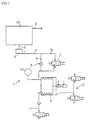
- Fig. 1 shows schematically a steam generator 1, having a steam generating chamber 13, shown as block, and which is provided with a steam outlet 2.
- a connection 3 for supply of water via a conduit 4 from a tank 5 maintaining a constant pressure and also for discharging water to a return tank 6.
- an operating valve 7 with a restriction 7a arranged in series therewith, whereas a return conduit 8 having a non-return valve 9 arranged therein is connected to the conduit 4, thus that it bridges the restriction 7a and the operating valve 7.
- the flow control formed in this manner is preferably a constant flow control.
- the tank 5 maintaining a constant pressure in turn is connected to a pressure sensor 10, and to a valve controlled water connection 11.
- the pressure maintaining tank 5 is equipped with a valve arrangement 12 for controlling pressure in and supply of water to the steam generating chamber.
- Fig.s 2-4 show in different sections, the very steam generating chamber, schematically and without connections and heating means.
- FIG. 2 is shown a cross section along line B-B in Fig. 3, through a heating body 13 acting as a steam generating chamber in the steam generator 1, whereas Fig. 3 shows a longitudinal section along line A-A in Fig. 2, and Fig. 4 shows a cross section along line C-C in Fig. 3.
- the heating body 13 consists of a extruded profile 14, preferably of aluminium, or another material having similar heat conducting properties.
- a centrally located, substantially keyhole-shaped steam generating chamber 15 with a lower portion 15 communicating with the inlet connection 3, a narrow, substantially vertically arranged slot-formed portion 17 and an upper, bigger portion 18, to which the steam outlet 2 is connected.
- channels 19 for accommodating not shown electric immersion heaters or for permitting through-flow of a heating medium.
- the heating chamber is closed off at the gables by means of preferably soldered, preferably extruded gables 20a, b, in the embodiment shown (20a in Fig. 4) equipped with channels 19a, corresponding to the channels 19 for heating purposes.
- the heating body can furthermore also otherwise consist of parts preferably interconnected by soldering.
- the steam generating chamber 15 is equipped with inserts 21, by means of which the bottom of the lower portion 16 slopes in a direction towards the centrum inlet and outlet 3 for water.
- the heating body 13 manufactured of aluminium or the like, is first heated to a temperature, high above the vaporization temperature of the water in order to store energy.
- the slot walls may have a coating, which has a capillary effect and a lower coefficient of thermal conductivity than the material of the very heating body 13.
- the water does not form a gas film on the coating surface but can be conducted via the capillary effect into the metal.
- the wall is equipped with not shown ridges projecting inwardly towards the centre line of the slot, and which are cooled at different speed at the crests and at the bottoms of the ridges, and for this reason there are always positions between the crest and bottom, which has an appropriate temperature for evaporization.
- the gas film which reduces the thermal transfer is broken up more easily.
- the energy stored in the heating body can transfer water into steam very rapidly.
- the water level in the slot-formed portion 17 is controlled.
- the inlet valve 7 is closed. This supervision can be achieved via temperature measurement in the area of the slot.
- the valve 7 is again opened.
- the steam pressure is maintained in that the steam generator is fed at a predetermined water pressure via cooperation between the valve 7, the restriction 7a and the non-return valve 9, and with pressurization from the pressure chamber 5. As long as the steam consumption is higher than the capacity of the generator, the steam consumption will control the water level in the steam generating chamber.
- shut-off steam generator is dry reduces the risk for corrosion.
Landscapes
- Engineering & Computer Science (AREA)
- Thermal Sciences (AREA)
- General Engineering & Computer Science (AREA)
- Mechanical Engineering (AREA)
- Physics & Mathematics (AREA)
- Sustainable Energy (AREA)
- Life Sciences & Earth Sciences (AREA)
- Sustainable Development (AREA)
- Air Humidification (AREA)
- Cookers (AREA)
- Commercial Cooking Devices (AREA)
- Detergent Compositions (AREA)
- Organic Low-Molecular-Weight Compounds And Preparation Thereof (AREA)
- Apparatus For Disinfection Or Sterilisation (AREA)
- Feeding, Discharge, Calcimining, Fusing, And Gas-Generation Devices (AREA)
Claims (12)
- Dampfgenerator der Art, die einen Heizkörper (13) einschließt, der mit Mitteln (19) für die Zufuhr von Wärme zu dem Körper und mit zumindest einem inneren Hohlraum (15) versehen ist, der mit einem Anschluß (3) für die Zufuhr von Wasser, das verdampft wird, und mit einem Auslaß (2) für Wasser, das in Dampf umgewandelt wurde, versehen ist dadurch gekennzeichnet, daß der Anschluß (3) des Dampfgenerators für die Zufuhr von Wasser im Boden des Hohlraums (15) angebracht ist und daß der Dampfgenerator mit einem Regelsystem (4-12) ausgerüstet ist, das die Zufuhr und auch das Ablassen von Wasser über den Anschluß (3) gestattet und das so gestaltet ist, daß es, unabhängig von der Richtung des Wasserflusses, einen gleichbleibenden Zuführdruck auf das Wasser aufrecht erhält.
- Dampfgenerator nach Anspruch 1, dadurch gekennzeichnet, daß das Regelsystem Mittel (7, 7a, 9) für die Durchflußregelung bezüglich der Wasserzufuhr von dem Wasserauslaß (3), der in dem Heizkörper angebracht ist, in den inneren Hohlraum (15) des Heizkörpers einschließt.
- Dampfgenerator nach Anspruch 1 oder 2, dadurch gekennzeichnet, daß der Auslaß (3) mit einem Rückschlagventil (9) für das Entleeren des Hohlraums (15) des Heizkörpers versehen ist, wenn das Regelsystem abgeschaltet wird.
- Dampfgenerator nach einem der vorhergehenden Ansprüche, dadurch gekennzeichnet, daß der Hohlraum (15) des Heizkörpers einen Boden (21) aufweist, der zu dem Auslaßanschluß (3) hin schräg verläuft.
- Dampfgenerator nach Anspruch 1, dadurch gekennzeichnet, daß der Hohlraum (15) des Heizkörpers einen Abschnitt (17) mit im wesentlichen vertikalen Oberflächen aufweist, über die, zum Zweck der Verdampfung, im wesentlichen die Wärmeübertragung zwischen Heizkörper und Wasser erfolgt.
- Dampfgenerator nach Anspruch 5, dadurch gekennzeichnet, daß der Hohlraum (15) des Heizkörpers in dem Abschnitt (16, 17) ein Volumen aufweist, das, verglichen mit dem Volumen des Heizkörpers, sehr klein ist und in dem die Verdampfung erfolgt, wodurch nur ein kleines Wasservolumen für die Verdampfung erhitzt werden muß und wodurch das Volumen von erhitztem Rücklaufwasser, das die Kammer über den Auslaß verlassen könnte, klein wird.
- Dampfgenerator nach Anspruch 5 oder 6, dadurch gekennzeichnet, daß die Oberflächen zumindest des wichtigsten dampferzeugenden Abschnitts (17) des Heizkörpers eine poröse Beschichtung aufweisen, deren Wärmeleitfähigkeit geringer ist als die des Materials in dem Heizkörper.
- Dampfgenerator nach einem der Ansprüche 5-7, dadurch gekennzeichnet, daß die Wände des Hohlraums (15) des Heizkörpers zumindest in dem Abschnitt (17), in dem die Verdampfung erfolgt, mit nach innen überstehenden Kanten versehen sind, die so gestaltet sind, daß sie immer einen geeigneten Bereich für die Verdampfung des Wassers schaffen, da die oberen und unteren Teile der Kanten unterschiedlich gekühlt werden.
- Dampfgenerator nach einem der vorhergehenden Ansprüche, dadurch gekennzeichnet, daß Mittel für die Überwachung der Temperatur in der Wand des Verdampfungsabschnitts (17) des Hohlraums in der Nähe des Anschlusses (3) angeordnet sind, um den Wasserstand in dem Hohlraum zu ermittelr.
- Dampfgenerator nach einem der vorhergehenden Ansprüche, dadurch gekennzeichnet, daß in Verbindung mit dem Auslaß (3) aus dem Hohlraum (15) des Heizkörpers ein Rücklauftank (6) vorgesehen ist, der ein Volumen aufweist, das für das Speichern von erhitztem Wasser geeignet ist, das aus dem Hohlraum herausfließt.
- Dampfgenerator nach einem der vorhergehenden Ansprüche, dadurch gekennzeichnet, daß der Heizkörper (13) durch Extrudieren hergestellt wird.
- Dampfgenerator nach einem der vorhergehenden Ansprüche, dadurch gekennzeichnet, daß der Heizkörper (13) aus Teilen (20a, 20b) besteht, die durch Löten miteinander verbunden wurden.
Applications Claiming Priority (3)
| Application Number | Priority Date | Filing Date | Title |
|---|---|---|---|
| SE9602396A SE509732C2 (sv) | 1996-06-18 | 1996-06-18 | Ånggenerator med reglerad till- och bortförsel av vatten |
| SE9602396 | 1996-06-18 | ||
| PCT/SE1997/001052 WO1997048947A1 (en) | 1996-06-18 | 1997-06-16 | Steam generator |
Publications (2)
| Publication Number | Publication Date |
|---|---|
| EP0906541A1 EP0906541A1 (de) | 1999-04-07 |
| EP0906541B1 true EP0906541B1 (de) | 2001-12-19 |
Family
ID=20403047
Family Applications (1)
| Application Number | Title | Priority Date | Filing Date |
|---|---|---|---|
| EP97928592A Expired - Lifetime EP0906541B1 (de) | 1996-06-18 | 1997-06-16 | Dampferzeuger |
Country Status (8)
| Country | Link |
|---|---|
| US (1) | US6135062A (de) |
| EP (1) | EP0906541B1 (de) |
| JP (1) | JP2000513428A (de) |
| AT (1) | ATE211235T1 (de) |
| AU (1) | AU3281197A (de) |
| DE (1) | DE69709350T2 (de) |
| SE (1) | SE509732C2 (de) |
| WO (1) | WO1997048947A1 (de) |
Families Citing this family (6)
| Publication number | Priority date | Publication date | Assignee | Title |
|---|---|---|---|---|
| ITUD20030134A1 (it) * | 2003-06-19 | 2004-12-20 | De Longhi Spa | Procedimento per produrre una caldaia a vapore per un elettrodomestico. |
| US9057516B2 (en) | 2011-11-28 | 2015-06-16 | Trimeteor Oil and Gas Corporation | Superheated steam generators |
| US9353611B2 (en) | 2012-11-02 | 2016-05-31 | Trimeteor Oil & Gas Corp. | Method and apparatus for the downhole injection of superheated steam |
| KR101981674B1 (ko) * | 2012-12-21 | 2019-05-24 | 삼성전자주식회사 | 조리기기 |
| ITMI20130373A1 (it) * | 2013-03-12 | 2014-09-13 | Absolute Up S R L | Autoclave |
| WO2015072509A1 (ja) * | 2013-11-15 | 2015-05-21 | 四国計測工業株式会社 | 高効率熱交換器および高効率熱交換方法 |
Family Cites Families (15)
| Publication number | Priority date | Publication date | Assignee | Title |
|---|---|---|---|---|
| SE161717C1 (de) * | ||||
| US1770980A (en) * | 1926-12-30 | 1930-07-22 | Mccord Radiator & Mfg Co | Steam generator for motor-vehicle heaters |
| JPS51117205A (en) * | 1975-04-04 | 1976-10-15 | Strobel & Soehne Gmbh & Co J | Steam generating machine |
| US4288674A (en) * | 1980-04-21 | 1981-09-08 | Councell Graham D | Microwave actuated steam generator |
| US4408116A (en) * | 1980-09-22 | 1983-10-04 | Superthermal, Inc. | Superheated steam generator |
| SE429472B (sv) * | 1982-02-22 | 1983-09-05 | Acela Pump Ab | Angalstrare fremst avsedd for intermittent drift |
| FI82303C (fi) * | 1984-05-04 | 1991-02-11 | Kauko Rautio | Luftfuktare. |
| WO1988002087A2 (en) * | 1986-09-08 | 1988-03-24 | Michael Laumen Thermotechnik | Continuous steam generator and steam recovery unit |
| ATE76955T1 (de) * | 1987-08-01 | 1992-06-15 | Elena Ronchi | Schnelldampferzeuger fuer haushalts- und fachgebrauch. |
| WO1990006477A2 (en) * | 1988-12-06 | 1990-06-14 | Dimplex Heating Limited | An electric boiler and controls therefor |
| US5371828A (en) * | 1991-08-28 | 1994-12-06 | Mks Instruments, Inc. | System for delivering and vaporizing liquid at a continuous and constant volumetric rate and pressure |
| US5471556A (en) * | 1993-07-16 | 1995-11-28 | Friedheim; Max | Superheated vapor generator and control system and method |
| IT1273174B (it) * | 1994-05-04 | 1997-07-07 | R E A S N C Di Sassi E Baudin | Generatore di vapore istantaneo monostadio |
| US5553188A (en) * | 1995-02-24 | 1996-09-03 | Mks Instruments, Inc. | Vaporizer and liquid delivery system using same |
| US5949958A (en) * | 1995-06-07 | 1999-09-07 | Steris Corporation | Integral flash steam generator |
-
1996
- 1996-06-18 SE SE9602396A patent/SE509732C2/sv not_active IP Right Cessation
-
1997
- 1997-06-16 AU AU32811/97A patent/AU3281197A/en not_active Abandoned
- 1997-06-16 US US09/202,603 patent/US6135062A/en not_active Expired - Fee Related
- 1997-06-16 JP JP10502793A patent/JP2000513428A/ja active Pending
- 1997-06-16 WO PCT/SE1997/001052 patent/WO1997048947A1/en not_active Ceased
- 1997-06-16 DE DE69709350T patent/DE69709350T2/de not_active Expired - Fee Related
- 1997-06-16 EP EP97928592A patent/EP0906541B1/de not_active Expired - Lifetime
- 1997-06-16 AT AT97928592T patent/ATE211235T1/de not_active IP Right Cessation
Also Published As
| Publication number | Publication date |
|---|---|
| AU3281197A (en) | 1998-01-07 |
| SE9602396D0 (sv) | 1996-06-18 |
| US6135062A (en) | 2000-10-24 |
| SE509732C2 (sv) | 1999-03-01 |
| DE69709350D1 (de) | 2002-01-31 |
| EP0906541A1 (de) | 1999-04-07 |
| ATE211235T1 (de) | 2002-01-15 |
| DE69709350T2 (de) | 2002-09-26 |
| JP2000513428A (ja) | 2000-10-10 |
| WO1997048947A1 (en) | 1997-12-24 |
| SE9602396L (sv) | 1997-12-19 |
Similar Documents
| Publication | Publication Date | Title |
|---|---|---|
| US6094523A (en) | Integral flash steam generator | |
| US5881207A (en) | Steam generator with automatic supply and a process for measuring the level of liquid in such a generator | |
| KR102114427B1 (ko) | 전극 보일러 시스템 | |
| EP0906541B1 (de) | Dampferzeuger | |
| KR20220054266A (ko) | 전극 보일러 시스템 | |
| KR100512043B1 (ko) | 전기보일러 | |
| US3119004A (en) | Flash chamber | |
| KR102097068B1 (ko) | 복합보일러 | |
| KR100502575B1 (ko) | 열교환식 보일러 | |
| JPS5950903B2 (ja) | 熱交換器 | |
| JP7124591B2 (ja) | 蒸気発生装置 | |
| KR100627720B1 (ko) | 전기보일러의 구조 | |
| CN1222225A (zh) | 蒸汽发生器 | |
| US4617910A (en) | Apparatus and method for producing and storing heated liquid | |
| KR200218928Y1 (ko) | 스팀발생기 | |
| RU2148215C1 (ru) | Электродный нагреватель | |
| JP2002062074A (ja) | 液化ガス蒸発装置 | |
| RU2087796C1 (ru) | Установка для получения тепла (система обогрева) | |
| KR20240062780A (ko) | 물이 거꾸로 순환되는 태양열 집열장치 | |
| RU1836601C (ru) | Водонагреватель | |
| CN119867504A (zh) | 一种高蒸汽生成效率的蒸汽发生器及烹饪设备 | |
| KR900009690Y1 (ko) | 냉 · 온수기의 급수파이프 및 냉수배출 장치 | |
| US3225750A (en) | Control apparatus | |
| CN115055640A (zh) | 一种余热回收系统 | |
| KR20200075368A (ko) | 순간 온수모듈 |
Legal Events
| Date | Code | Title | Description |
|---|---|---|---|
| PUAI | Public reference made under article 153(3) epc to a published international application that has entered the european phase |
Free format text: ORIGINAL CODE: 0009012 |
|
| 17P | Request for examination filed |
Effective date: 19990118 |
|
| AK | Designated contracting states |
Kind code of ref document: A1 Designated state(s): AT BE CH DE DK ES FI FR GB GR IE IT LI NL PT SE |
|
| GRAG | Despatch of communication of intention to grant |
Free format text: ORIGINAL CODE: EPIDOS AGRA |
|
| 17Q | First examination report despatched |
Effective date: 20010301 |
|
| GRAG | Despatch of communication of intention to grant |
Free format text: ORIGINAL CODE: EPIDOS AGRA |
|
| GRAH | Despatch of communication of intention to grant a patent |
Free format text: ORIGINAL CODE: EPIDOS IGRA |
|
| GRAH | Despatch of communication of intention to grant a patent |
Free format text: ORIGINAL CODE: EPIDOS IGRA |
|
| GRAA | (expected) grant |
Free format text: ORIGINAL CODE: 0009210 |
|
| AK | Designated contracting states |
Kind code of ref document: B1 Designated state(s): AT BE CH DE DK ES FI FR GB GR IE IT LI NL PT SE |
|
| PG25 | Lapsed in a contracting state [announced via postgrant information from national office to epo] |
Ref country code: NL Free format text: LAPSE BECAUSE OF FAILURE TO SUBMIT A TRANSLATION OF THE DESCRIPTION OR TO PAY THE FEE WITHIN THE PRESCRIBED TIME-LIMIT Effective date: 20011219 Ref country code: LI Free format text: LAPSE BECAUSE OF FAILURE TO SUBMIT A TRANSLATION OF THE DESCRIPTION OR TO PAY THE FEE WITHIN THE PRESCRIBED TIME-LIMIT Effective date: 20011219 Ref country code: IT Free format text: LAPSE BECAUSE OF FAILURE TO SUBMIT A TRANSLATION OF THE DESCRIPTION OR TO PAY THE FEE WITHIN THE PRE;WARNING: LAPSES OF ITALIAN PATENTS WITH EFFECTIVE DATE BEFORE 2007 MAY HAVE OCCURRED AT ANY TIME BEFORE 2007. THE CORRECT EFFECTIVE DATE MAY BE DIFFERENT FROM THE ONE RECORDED.SCRIBED TIME-LIMIT Effective date: 20011219 Ref country code: GR Free format text: LAPSE BECAUSE OF FAILURE TO SUBMIT A TRANSLATION OF THE DESCRIPTION OR TO PAY THE FEE WITHIN THE PRESCRIBED TIME-LIMIT Effective date: 20011219 Ref country code: FI Free format text: LAPSE BECAUSE OF FAILURE TO SUBMIT A TRANSLATION OF THE DESCRIPTION OR TO PAY THE FEE WITHIN THE PRESCRIBED TIME-LIMIT Effective date: 20011219 Ref country code: CH Free format text: LAPSE BECAUSE OF FAILURE TO SUBMIT A TRANSLATION OF THE DESCRIPTION OR TO PAY THE FEE WITHIN THE PRESCRIBED TIME-LIMIT Effective date: 20011219 Ref country code: BE Free format text: LAPSE BECAUSE OF FAILURE TO SUBMIT A TRANSLATION OF THE DESCRIPTION OR TO PAY THE FEE WITHIN THE PRESCRIBED TIME-LIMIT Effective date: 20011219 Ref country code: AT Free format text: LAPSE BECAUSE OF FAILURE TO SUBMIT A TRANSLATION OF THE DESCRIPTION OR TO PAY THE FEE WITHIN THE PRESCRIBED TIME-LIMIT Effective date: 20011219 |
|
| REF | Corresponds to: |
Ref document number: 211235 Country of ref document: AT Date of ref document: 20020115 Kind code of ref document: T |
|
| REG | Reference to a national code |
Ref country code: CH Ref legal event code: EP |
|
| REG | Reference to a national code |
Ref country code: GB Ref legal event code: IF02 |
|
| REG | Reference to a national code |
Ref country code: IE Ref legal event code: FG4D |
|
| REF | Corresponds to: |
Ref document number: 69709350 Country of ref document: DE Date of ref document: 20020131 |
|
| PG25 | Lapsed in a contracting state [announced via postgrant information from national office to epo] |
Ref country code: SE Free format text: LAPSE BECAUSE OF FAILURE TO SUBMIT A TRANSLATION OF THE DESCRIPTION OR TO PAY THE FEE WITHIN THE PRESCRIBED TIME-LIMIT Effective date: 20020319 Ref country code: PT Free format text: LAPSE BECAUSE OF FAILURE TO SUBMIT A TRANSLATION OF THE DESCRIPTION OR TO PAY THE FEE WITHIN THE PRESCRIBED TIME-LIMIT Effective date: 20020319 Ref country code: DK Free format text: LAPSE BECAUSE OF FAILURE TO SUBMIT A TRANSLATION OF THE DESCRIPTION OR TO PAY THE FEE WITHIN THE PRESCRIBED TIME-LIMIT Effective date: 20020319 |
|
| NLV1 | Nl: lapsed or annulled due to failure to fulfill the requirements of art. 29p and 29m of the patents act | ||
| ET | Fr: translation filed | ||
| PG25 | Lapsed in a contracting state [announced via postgrant information from national office to epo] |
Ref country code: GB Free format text: LAPSE BECAUSE OF NON-PAYMENT OF DUE FEES Effective date: 20020616 |
|
| PG25 | Lapsed in a contracting state [announced via postgrant information from national office to epo] |
Ref country code: IE Free format text: LAPSE BECAUSE OF NON-PAYMENT OF DUE FEES Effective date: 20020617 |
|
| PG25 | Lapsed in a contracting state [announced via postgrant information from national office to epo] |
Ref country code: ES Free format text: LAPSE BECAUSE OF FAILURE TO SUBMIT A TRANSLATION OF THE DESCRIPTION OR TO PAY THE FEE WITHIN THE PRESCRIBED TIME-LIMIT Effective date: 20020627 |
|
| REG | Reference to a national code |
Ref country code: CH Ref legal event code: PL |
|
| PLBE | No opposition filed within time limit |
Free format text: ORIGINAL CODE: 0009261 |
|
| STAA | Information on the status of an ep patent application or granted ep patent |
Free format text: STATUS: NO OPPOSITION FILED WITHIN TIME LIMIT |
|
| 26N | No opposition filed | ||
| PG25 | Lapsed in a contracting state [announced via postgrant information from national office to epo] |
Ref country code: DE Free format text: LAPSE BECAUSE OF NON-PAYMENT OF DUE FEES Effective date: 20030101 |
|
| GBPC | Gb: european patent ceased through non-payment of renewal fee |
Effective date: 20020616 |
|
| PG25 | Lapsed in a contracting state [announced via postgrant information from national office to epo] |
Ref country code: FR Free format text: LAPSE BECAUSE OF NON-PAYMENT OF DUE FEES Effective date: 20030228 |
|
| REG | Reference to a national code |
Ref country code: IE Ref legal event code: MM4A |
|
| REG | Reference to a national code |
Ref country code: FR Ref legal event code: ST |
|
| NLV1 | Nl: lapsed or annulled due to failure to fulfill the requirements of art. 29p and 29m of the patents act |