EP0905917A2 - Multimode wireless communication system - Google Patents
Multimode wireless communication system Download PDFInfo
- Publication number
- EP0905917A2 EP0905917A2 EP98118212A EP98118212A EP0905917A2 EP 0905917 A2 EP0905917 A2 EP 0905917A2 EP 98118212 A EP98118212 A EP 98118212A EP 98118212 A EP98118212 A EP 98118212A EP 0905917 A2 EP0905917 A2 EP 0905917A2
- Authority
- EP
- European Patent Office
- Prior art keywords
- signal
- frequency
- communication systems
- mixer
- band
- Prior art date
- Legal status (The legal status is an assumption and is not a legal conclusion. Google has not performed a legal analysis and makes no representation as to the accuracy of the status listed.)
- Granted
Links
- 238000004891 communication Methods 0.000 title claims abstract description 55
- 230000005540 biological transmission Effects 0.000 claims description 30
- 239000000919 ceramic Substances 0.000 claims description 6
- 239000000758 substrate Substances 0.000 claims description 2
- 230000009977 dual effect Effects 0.000 description 15
- 238000010586 diagram Methods 0.000 description 9
- 230000015556 catabolic process Effects 0.000 description 2
- 238000006731 degradation reaction Methods 0.000 description 2
- 230000002146 bilateral effect Effects 0.000 description 1
- 238000007796 conventional method Methods 0.000 description 1
- 238000001514 detection method Methods 0.000 description 1
- 238000004519 manufacturing process Methods 0.000 description 1
Images


Classifications
-
- H—ELECTRICITY
- H04—ELECTRIC COMMUNICATION TECHNIQUE
- H04B—TRANSMISSION
- H04B1/00—Details of transmission systems, not covered by a single one of groups H04B3/00 - H04B13/00; Details of transmission systems not characterised by the medium used for transmission
- H04B1/005—Details of transmission systems, not covered by a single one of groups H04B3/00 - H04B13/00; Details of transmission systems not characterised by the medium used for transmission adapting radio receivers, transmitters andtransceivers for operation on two or more bands, i.e. frequency ranges
- H04B1/0053—Details of transmission systems, not covered by a single one of groups H04B3/00 - H04B13/00; Details of transmission systems not characterised by the medium used for transmission adapting radio receivers, transmitters andtransceivers for operation on two or more bands, i.e. frequency ranges with common antenna for more than one band
- H04B1/0057—Details of transmission systems, not covered by a single one of groups H04B3/00 - H04B13/00; Details of transmission systems not characterised by the medium used for transmission adapting radio receivers, transmitters andtransceivers for operation on two or more bands, i.e. frequency ranges with common antenna for more than one band using diplexing or multiplexing filters for selecting the desired band
-
- H—ELECTRICITY
- H03—ELECTRONIC CIRCUITRY
- H03D—DEMODULATION OR TRANSFERENCE OF MODULATION FROM ONE CARRIER TO ANOTHER
- H03D7/00—Transference of modulation from one carrier to another, e.g. frequency-changing
- H03D7/16—Multiple-frequency-changing
-
- H—ELECTRICITY
- H03—ELECTRONIC CIRCUITRY
- H03D—DEMODULATION OR TRANSFERENCE OF MODULATION FROM ONE CARRIER TO ANOTHER
- H03D7/00—Transference of modulation from one carrier to another, e.g. frequency-changing
- H03D7/16—Multiple-frequency-changing
- H03D7/161—Multiple-frequency-changing all the frequency changers being connected in cascade
- H03D7/163—Multiple-frequency-changing all the frequency changers being connected in cascade the local oscillations of at least two of the frequency changers being derived from a single oscillator
-
- H—ELECTRICITY
- H04—ELECTRIC COMMUNICATION TECHNIQUE
- H04B—TRANSMISSION
- H04B1/00—Details of transmission systems, not covered by a single one of groups H04B3/00 - H04B13/00; Details of transmission systems not characterised by the medium used for transmission
- H04B1/005—Details of transmission systems, not covered by a single one of groups H04B3/00 - H04B13/00; Details of transmission systems not characterised by the medium used for transmission adapting radio receivers, transmitters andtransceivers for operation on two or more bands, i.e. frequency ranges
- H04B1/0053—Details of transmission systems, not covered by a single one of groups H04B3/00 - H04B13/00; Details of transmission systems not characterised by the medium used for transmission adapting radio receivers, transmitters andtransceivers for operation on two or more bands, i.e. frequency ranges with common antenna for more than one band
- H04B1/006—Details of transmission systems, not covered by a single one of groups H04B3/00 - H04B13/00; Details of transmission systems not characterised by the medium used for transmission adapting radio receivers, transmitters andtransceivers for operation on two or more bands, i.e. frequency ranges with common antenna for more than one band using switches for selecting the desired band
-
- H—ELECTRICITY
- H04—ELECTRIC COMMUNICATION TECHNIQUE
- H04B—TRANSMISSION
- H04B1/00—Details of transmission systems, not covered by a single one of groups H04B3/00 - H04B13/00; Details of transmission systems not characterised by the medium used for transmission
- H04B1/38—Transceivers, i.e. devices in which transmitter and receiver form a structural unit and in which at least one part is used for functions of transmitting and receiving
- H04B1/40—Circuits
- H04B1/403—Circuits using the same oscillator for generating both the transmitter frequency and the receiver local oscillator frequency
- H04B1/405—Circuits using the same oscillator for generating both the transmitter frequency and the receiver local oscillator frequency with multiple discrete channels
-
- H—ELECTRICITY
- H04—ELECTRIC COMMUNICATION TECHNIQUE
- H04B—TRANSMISSION
- H04B1/00—Details of transmission systems, not covered by a single one of groups H04B3/00 - H04B13/00; Details of transmission systems not characterised by the medium used for transmission
- H04B1/38—Transceivers, i.e. devices in which transmitter and receiver form a structural unit and in which at least one part is used for functions of transmitting and receiving
- H04B1/40—Circuits
- H04B1/403—Circuits using the same oscillator for generating both the transmitter frequency and the receiver local oscillator frequency
- H04B1/406—Circuits using the same oscillator for generating both the transmitter frequency and the receiver local oscillator frequency with more than one transmission mode, e.g. analog and digital modes
Definitions
- the present invention relates to a wireless telegraph usable for a plurality of different communication systems in a mobile digital communication portable terminal.
- the wireless telegraph is divided into a transmitter and a receiver in the description.
- signals I and Q are entered to an input terminal of a signal modulator that can modulate a plurality of different signals. Passing the signal modulator, the frequencies of both the signals I and Q are changed in a multiplying circuit of a mixer according to a signal output from the first local oscillator.
- the signals I and Q pass a transmission band-pass filter, so that only a desired frequency is amplified in a power amplifier.
- the frequency-amplified signal then passes an antenna switch, so that only a desired signal is output from an antenna terminal.
- the receiver receives a desired signal via the antenna terminal. Then, the received signal passes the antenna switch and a receiving band-pass filter, so that the received signal is amplified by a low noise power amplifier.
- the frequency of the received signal is changed by a multiplying circuit of a receiving mixer. Then, the received signal passes the second receiving band-pass filter that passes lower frequencies than the receiving band-pass filter. The frequency of the received signal is then changed using a frequency from the second local oscillator. After this, the received signal passes the third receiving band-pass filter, so that the received signals I and Q are demodulated with two types of phase signals.
- the configuration of the related art portable telephone is used as is for services of a plurality of communication systems, the number of parts in such a portable telephone will become double those of a portable telephone for a single communication system even in a rough estimation. And, the size of the portable telephone itself will become about double and accordingly, the telephone will become more heavy.
- the first invention of the present invention is a wireless telegraph corresponding to a plurality communication systems, comprising means for modulating signals of a plurality of communication systems; means for oscillating a signal of a predetermined frequency; means for dividing a signal from said oscillating means by a factor of N; and a mixer for entering a signal output from said oscillating means or said N-divided signal and a signal from said modulating means, then outputting a signal of a predetermined frequency.
- the second invention of the present invention is a wireless telegraph corresponding to a plurality communication systems, comprising means for modulating I and Q signals of a plurality of communication systems; first means for oscillating a signal of a predetermined frequency; variable dividing means that can vary its dividing number according to each of a plurality of said communication systems; a mixer for entering said divided signal and a signal output from said modulating means, then outputting a signal of a predetermined frequency; a transmission band-pass filter for passing a signal of said predetermined frequency; a transmission amplifier for amplifying a transmission frequency signal that has passed said transmission band-pass filter; first receiving band-pass filter for passing a received signal; a receiving amplifier for amplifying a received signal that has passed said first receiving band-pass filter; first receiving mixer for entering said amplified received signal and a signal output from said first oscillating means, then outputting first intermediate frequency signal; and second receiving band-pass filter for passing a signal from said first receiving mixer.
- the eleventh invention of the present invention is a wireless telegraph corresponding to two transmission frequencies, wherein first frequency is double or around double second frequency, comprising first local oscillator for oscillating a signal of first local frequency; a P-divider for dividing said first local frequency signal by a factor of P; second local oscillator for oscillating a signal of second local frequency; a Q-divider for dividing said second local frequency signal by a factor of Q; first mixer for entering said first and second local frequency signals and outputting a signal of said first frequency; and second mixer for entering said P-divided first local frequency signal and said Q-divided second local frequency signal and outputting said second frequency signal.
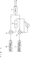
- Fig.1 is a block diagram for the portion around a transmission mixer provided in a dual mode wireless telegraph corresponding to a plurality of communication systems in the first embodiment of the present invention. In this embodiment, the transmitter of portable telephone services will be described.
- signals I and Q are entered to an input terminal of a modulator 11 that can modulate a plurality of communication signals as transmit signals. Passing the modulator 11, the frequencies of the signals I and Q are changed by a multiplying circuit of a high frequency mixer 13 according to a signal output from the first local oscillator 14. The signals I and Q are then output to a high frequency output part (output terminal) 17 from the high frequency mixer 13. Otherwise, the frequencies of the signals I and Q are changed by a multiplying circuit of a low frequency mixer 12 according to a signal output from the first local oscillator via an N-divider 15. The signal I and Q are then output to a low frequency output part (output terminal) from the low frequency mixer 12.
- the modulator 11 corresponds to the modulating means and the first local oscillator 14 corresponds to the oscillating means of the present invention respectively.
- the N-divider 15 corresponds to the N-dividing means of the present invention.
- phase angles of the signals I and Q entered to the modulator 11 differ 90 degrees from each other.
- the dual mode wireless telegraph in this embodiment means a portable terminal that can use two types of portable telephone services for communication systems per unit.
- the specifications are as follows; the GSM system is assumed for the low service frequency (around 900 MHz) used widely in Europe and the DCS1800 system is assumed for the high frequency side service frequency (around 1800 MHz).
- the DCS1800 system is an expanded version of the GSM system.
- the GSM system uses a lower frequency band than the DCS system. Consequently, when the user selects any one of those systems actually, the dual mode wireless telegraph senses the service frequency for the selected system by itself and sets the low or high frequency service environment automatically.
- Such a automatic setting of the service environment is realized by the following conventional method.
- a transmit signal output from an extension of a portable telephone is transmitted to the base station first to judge whether or not it is possible to make bilateral communications therebetween. For example, at first, communications with the base station are checked in the low frequency mode. If the base station sends back a response, the low frequency mode is continued. If not, the mode is changed to the high frequency one and the high frequency transmitter is started. If communications with the base station are enabled in the high frequency mode, the mode is continued. If not, it is judged that communications are disabled in any mode.
- a modulated signal from the modulator 11 is transmitted to both the low frequency mixer 12 and the high frequency mixer 13.
- the frequency of a 1800 MHz signal to be entered to the low frequency mixer 16 from the first local oscillator 14 is divided by a factor of N, but the 1800 MHz signal is entered to the high frequency mixer 17 as is.
- a signal output from the first local oscillator 14 is entered to the N-divider 15 so that the frequency of the signal is divided into 900 MHz.
- the high frequency mixer is entered the 1800 MHz signal as is.
- a modulated signal from the modulator 11 and the 900 MHz signal from the N-divider 15 are entered to the low frequency mixer 12 such way. Furthermore, a modulated signal from the modulator 11 and the 1800 MHz signal from the first local oscillator 14 are entered to the high frequency mixer 13.
- the corresponding control signal is transmitted to both the low frequency mixer 12 and the high frequency mixer 13. Consequently, the low frequency mixer 12 runs and the high frequency mixer 13 stops.
- signals from either of the low frequency mixer 12 or the high frequency mixer 13 are output to the low frequency output part (output terminal) 16 or the high frequency output part (output terminal) 17 such way.
- the dividing number of the frequency from the first oscillator is decided in the designing stage so as not to affect the actual transmission and receiving frequencies, as well as to reduce unnecessary spurious outputs as much as possible. Consequently, the optimal frequency is not necessarily only one.
- the wireless telegraph is provided with at least one N-divider 15 such way, it is possible to generate a plurality of signals on the basis of the signal from the first local oscillator 14.
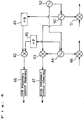
- Figs.2 and 3 are block diagrams for a triple mode wireless telegraph corresponding to a plurality of communication systems in the second embodiment of the present invention. Although the block diagram of this triple mode wireless telegraph is divided as shown in Figs.2 and 3, both diagrams of the telegraph are connected actually to each other at portions indicated with 1 ⁇ to 4 ⁇ in Figs.2 and 3.
- This triple mode wireless telegraph is composed on the basis of the dual mode telegraph in the first embodiment, but modified to use the communication system called PCS1900 serviced in the United States of America.
- the transmitter transmits signals I and Q to an input terminal of the modulator 21 that can modulate a plurality of communication signals. Passing the modulator 21, the frequencies of the signals I and Q are changed by a multiplying circuit provided in a transmission mixer 22 according to a signal output from the first local oscillator 24. The signal from the first local oscillator 24 is divided by the N-divider 25 used as variable dividing means. The signals are then output from the mixer 22. The phase angles of the signals I and Q entered to the modulator 21 differ 90 degrees from each other.
- the triple mode wireless telegraph in this embodiment is designed so that the oscillating frequency of the first local oscillator 24 becomes 1424 to 1464 MHz when the GSM system is used and 1368 to 1428 MHz when the DCS1800 (PCN) system is used.
- the oscillating frequency becomes 1480 to 1528 MHz.
- the triple mode telegraph judges the service environment by itself just like in the first embodiment, so that the first local oscillator 24 outputs a signal within the frequency band corresponding to the service environment.
- the signal is then entered to the mixer 22 via the N-divider as the first local signal.
- the first local oscillator 24 outputs a signal within 1368 to 1428 MHz and the signal is entered to the mixer 22 as the first local signal.
- the frequency of a 1368 to 1428 MHz signal is not divided at this time.
- the first local oscillator 24 outputs a signal within 1480 to 1528 MHz and the signal is entered to the mixer 22 as the first local signal.
- the 1489 to 1528 MHz signal is not divided at this time.
- the oscillating frequency of the low frequency local oscillator 501 is set to 644 to 669 MHz just like the single mode wireless telegraph corresponding to the conventional GSM system.
- the oscillating frequency of the high frequency local oscillator 502 is set to 1464 to 1539 MHz or 1604 to 1664 MHz just like the single mode wireless telegraph corresponding to the conventional PCN system or the PCS system.
- the oscillating frequency becomes 644 to 1539 MHz, so a band width of about 900 MHz is needed.
- the oscillating frequency becomes 644 to 1664 MHz, so a band width of 1 GHz is needed.
- the oscillating range required by one first local oscillator is 1368 to 1528 MHz.
- the oscillating frequency of the first local oscillator 24 is about 150 MHz in band width.
- the oscillating frequency band width is reduced only to about 1/10.
- the portable terminal is not affected by the expected degradation of the electrical characteristics so much.
- the number of oscillators can be reduced, so that the portable terminal becomes more compact in size and light in weight than the conventional one.
- the GSM system should be used for the low frequency side service frequency and the PCS system should be used for the high frequency side service frequency. Consequently, only one first local oscillator 14 can cope with an oscillating frequency range within 1424 to 1528 MHz. It is thus only needed to provide the band width with about 100 MHz.
- signals to be entered to the transmission modulator 21 are two signals whose phase angles are divided into two parts respectively in the phase signal generator 61 so that their phase angles differ 90 degrees from each other.
- Those two signals are generated by dividing the frequency output from the first local oscillator 24 using a factor of N in the N-divider 25 according to a frequency corresponding to the result of the above automatic detection of a service environment, then dividing the frequency further by a factor of M in the M-divider.
- the N and M in this case are real numbers over 1 respectively.
- the M is assumed to be 2.
- the N value of the divider 25 is set to 1.
- the N value is set to 2.
- the M-divider 60 and the phase signal generator 61 correspond to the phase signal generating means for modulation of the present invention.
- the mixer 22 If a signal of the above frequency is entered to the mixer 22, the mixer 22 outputs a frequency as shown below according to the communication system in use.
- the frequency range is within 890 to 915 MHz and when the DCS1800 system is used, the frequency range is within 1710 to 1785 MHz. When the PCS1900 system is used, the frequency range is within 1850 to 1910 MHz.
- the frequency of a signal output from each device will be as shown below.
- the output from the M-divider 60 is within 356 to 366 MHz.
- the phase signal generator 61 divides a signal output from the M-divider 60 by a factor of 2.
- the output from the phase signal generator 61 to the modulator 21 is within 178 to 183 MHz. Consequently, the mixer 22 receives a signal of 890 to 915 MHz, which is obtained by adding a signal of 712 to 732 MHz output from the N-divider to a signal of 178 to 183 MHz output from the modulator 21.
- the above outputs are also obtained even when other systems are used.
- Each of the above signals which is appropriate to each service, is transmitted to the power amplifier (PA) 27 used as a transmission amplifier via a transmission band-pass filter of the laminated planer 26.
- the signal is amplified there and transmitted from a terminal of the antenna 29 via the antenna switch 28.
- the same filter of the laminated planer 26 is also used for both DSC1800 and PCS1900 systems, since frequencies of those systems (high frequencies) are close to each other.
- a single filter unit is used for the low frequency GSM system. Since the laminated filter, which is a one-package filter, can be divided into two parts so as to have two passing band widths, the wireless telegraph can be reduced in both size and weight more significantly.
- the power amplifier 27 is also divided into two parts to cope with the frequency configuration of the wireless telegraph.
- the low frequency side GSM signal amplifier, the high frequency side PCN or PCS signal amplifier are housed in one package with a passage therebetween.
- the received signal passes the antenna switch 28.
- the signal then passes the laminated planer 30, which is the first receiving band-pass filter for each of the GSM, PCN, and PCS signals.
- the signal is then entered to the low noise power amplifier 31 (LNA) used as a receiving amplifier to be amplified there, so that only the signal necessary to receive GSM, PCN, and PCS signals is amplified.
- LNA low noise power amplifier
- the received signal frequency of the antenna 29 is set to 935 to 960 MHz and only the frequency that can pass the receiving mixer 32 is set to 432 MHz.
- a SAW filter 33 is used.
- the SAW filter 33 is a band-pass filter provided with sharp frequency characteristics and an excellent selectivity. If the passing frequency is set to 432 MHz, the frequency of the received first local signal becomes 1367 to 1392 MHz and a received signal (935 to 960 MHz) is subtracted from the frequency 1367 to 1392 MHz in the receiving mixer 32 thereby to obtain a 432 MHz received signal.
- the ceramic filter (CF) which is the second band-pass filter that passes lower frequencies than the receiving band-pass filter
- the oscillating frequency of the second local oscillator becomes 417.6 MHz, which is obtained by subtracting 14.4 MHz from 432 MHz.
- a voltage-controlled oscillator with temperature compensation (VCTCXO) 37 is used.
- the oscillator can obtain 28.8 MHz easily, which is double the 14.4 MHz frequency of the ceramic filter. Consequently, a 2-divider 62 is provided between the voltage-controlled oscillator with temperature compensation 37 and the demodulator 38. And, the phase generated in this 2-divider 62 is used to demodulate the signals I and Q in the demodulator 38 according to the two phase signals that differ 90 degrees from each other.
- the GSM frequency is picked up in the above description, if PCN frequency or the PCS frequency may also be picked up. If the PCN frequency or the PCS frequency is picked up, the passing frequency of the SAW filter 33 becomes 432 MHz just like the GSM system case after passing each laminated planer that passes signals of the PCN and PCS bands via the antenna 29 and being amplified in each low noise power amplifier 31.
- the frequency of received first local signal becomes 1373 to 1448 MHz and for the PCS frequency, the frequency of received first local signal becomes 1498 to 1558 MHz.
- the received signal frequency becomes 432 MHz if the frequency is subtracted in the receiving mixer 32 respectively. Thereafter, received signals are the same as those of the GSM system.
- this received first local frequency is set almost equally to the transmission side frequency described above, so only one oscillator can be used for both transmission and receiving.
- the same oscillator is also set so as to correspond to both low and high frequencies. Consequently, it is possible to reduce the number of parts, as well as both size and weight of the wireless telegraph significantly.
- the frequency of the receiving SAW filter 33 is set to 432 MHz
- the frequency of the ceramic filter 36 is set to 14.4 MHz
- the frequency of the second local oscillator for transmission 34 is set to 417.6 MHz
- the frequency of the voltage-controlled oscillator with temperature compensation 37 is set to 28.8 MHz respectively for manufacturing the wireless telegraph.
- the devices to be included in the above integrated circuit are the modulator 21, the transmission mixer 22, the first local oscillator 24, and the divider 25 in the transmit signal frequency changer, as well as a plurality of the low noise amplifiers 31 provided to correspond to a plurality of communication systems, the second local oscillator 34, the receiving mixers 32 and 35, the demodulator 38, and the voltage-controlled oscillator with temperature compensation 37 in the receiver.
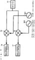
- Fig.4 is a schematic block diagram for the transmission side of a dual mode wireless telegraph corresponding to a plurality of communication systems in the third embodiment of the present invention.
- the low frequency side service frequency is the second frequency within 880 to 915 MHz
- the high frequency side service frequency is the first frequency within 1985 to 2015 MHz.
- the first frequency is double or close to double the second frequency.
- a signal within 1557 to 1587 MHz output from the first local oscillator 44 is entered to the high frequency mixer 43 used as the first mixer without passing the P-divider 45.
- a 428 MHz signal output from the second local oscillator 50 is entered to the high frequency mixer 43 without passing the Q-divider 49.
- a 1985 to 2015 MHz signal obtained by multiplying 1557 to 1587 MHz by 428 MHz is output from the high frequency output part (output terminal) 47.
- the mixer 48 which receives a signal from the first local oscillator, is the first mixer for receiving and the mixer 51 that receives a signal from the second local oscillator 50 is the second mixer for receiving.
- Signal sources used for this circuit configuration can also be used for all the encoded modulated signal systems such as CDMA included in a sine wave and a band width.
- one portable telephone can transmit and receive signals from and to a plurality of portable telephone systems. And, the size and weight of the portable telephone is still as small as one conventional portable telephone.
- the configuration is not limited only to those two ones.
- only one transmission mixer 22 may be provided (see Fig.3) as a variation of the first embodiment. Consequently, since the number of mixers can be reduced to only one, the size of the portable terminal can be reduced more significantly.
Landscapes
- Engineering & Computer Science (AREA)
- Computer Networks & Wireless Communication (AREA)
- Signal Processing (AREA)
- Power Engineering (AREA)
- Transceivers (AREA)
- Digital Transmission Methods That Use Modulated Carrier Waves (AREA)
- Mobile Radio Communication Systems (AREA)
- Transmitters (AREA)
Abstract
Description
- The present invention relates to a wireless telegraph usable for a plurality of different communication systems in a mobile digital communication portable terminal.
- Hereunder, description will be made for both configuration and operation of a wireless telegraph used in a related art portable telephone. The wireless telegraph is divided into a transmitter and a receiver in the description.
- At first, the transmitter of the related art portable telephone will be described.
- In the transmitter, signals I and Q are entered to an input terminal of a signal modulator that can modulate a plurality of different signals. Passing the signal modulator, the frequencies of both the signals I and Q are changed in a multiplying circuit of a mixer according to a signal output from the first local oscillator.
- After this, the signals I and Q pass a transmission band-pass filter, so that only a desired frequency is amplified in a power amplifier. The frequency-amplified signal then passes an antenna switch, so that only a desired signal is output from an antenna terminal.
- Next, the receiver of the related art portable telephone will be described.
- At first, the receiver receives a desired signal via the antenna terminal. Then, the received signal passes the antenna switch and a receiving band-pass filter, so that the received signal is amplified by a low noise power amplifier.
- After this, the frequency of the received signal is changed by a multiplying circuit of a receiving mixer. Then, the received signal passes the second receiving band-pass filter that passes lower frequencies than the receiving band-pass filter. The frequency of the received signal is then changed using a frequency from the second local oscillator. After this, the received signal passes the third receiving band-pass filter, so that the received signals I and Q are demodulated with two types of phase signals.
- On the other hand, there have been many types of portable telephone service communication systems. For example, the GSM system is used widely in Europe and the PDC and PHS systems are used widely in Japan, etc.
- When using each of those communication systems, therefore, the user must prepare portable telephones as many as the number of communication systems to be used. There has been no compact and light-weight portable telephone that can correspond to such a plurality of communication systems.
- If the configuration of the related art portable telephone is used as is for services of a plurality of communication systems, the number of parts in such a portable telephone will become double those of a portable telephone for a single communication system even in a rough estimation. And, the size of the portable telephone itself will become about double and accordingly, the telephone will become more heavy.
- Furthermore, in order to meet the above prerequisites, it is needed to develop and mount devices such as a wide-ranged oscillator, a mixer, each band-pass filter, an amplifier, etc. that are usable commonly for the frequency configuration of each of those communication systems. In addition, each of those devices must be reduced much more in both size and weight. Otherwise, they are not usable for such a compact and light-weight portable telephone. The related art portable telephone has been confronted with such problems.
- Under such the circumstances, it is an object of the present invention to provide a wireless telegraph that can solve the above related art problems and correspond to a plurality of communication systems while satisfying the wide range prerequisite of each of the devices, as well as it is possible to be reduced significantly in both size and weight.
- The first invention of the present invention is a wireless telegraph corresponding to a plurality communication systems, comprising means for modulating signals of a plurality of communication systems; means for oscillating a signal of a predetermined frequency; means for dividing a signal from said oscillating means by a factor of N; and a mixer for entering a signal output from said oscillating means or said N-divided signal and a signal from said modulating means, then outputting a signal of a predetermined frequency.
- The second invention of the present invention is a wireless telegraph corresponding to a plurality communication systems, comprising means for modulating I and Q signals of a plurality of communication systems; first means for oscillating a signal of a predetermined frequency; variable dividing means that can vary its dividing number according to each of a plurality of said communication systems; a mixer for entering said divided signal and a signal output from said modulating means, then outputting a signal of a predetermined frequency; a transmission band-pass filter for passing a signal of said predetermined frequency; a transmission amplifier for amplifying a transmission frequency signal that has passed said transmission band-pass filter; first receiving band-pass filter for passing a received signal; a receiving amplifier for amplifying a received signal that has passed said first receiving band-pass filter; first receiving mixer for entering said amplified received signal and a signal output from said first oscillating means, then outputting first intermediate frequency signal; and second receiving band-pass filter for passing a signal from said first receiving mixer.
- The eleventh invention of the present invention is a wireless telegraph corresponding to two transmission frequencies, wherein first frequency is double or around double second frequency, comprising first local oscillator for oscillating a signal of first local frequency; a P-divider for dividing said first local frequency signal by a factor of P; second local oscillator for oscillating a signal of second local frequency; a Q-divider for dividing said second local frequency signal by a factor of Q; first mixer for entering said first and second local frequency signals and outputting a signal of said first frequency; and second mixer for entering said P-divided first local frequency signal and said Q-divided second local frequency signal and outputting said second frequency signal.
-
- Fig.1 is a block diagram for the portion around a transmission mixer provided in a dual mode wireless telegraph corresponding to a plurality of communication systems in the first embodiment of the present invention.
- Fig.2 is a block diagram for the front part of a triple mode wireless telegraph corresponding to a plurality of communication systems in the second embodiment of the present invention.
- Fig.3 is a block diagram for the rear part of the triple mode wireless telegraph corresponding to a plurality of communication systems in the second embodiment shown in Fig.2.
- Fig.4 is a block diagram for the major portion of a dual mode wireless telegraph corresponding to a plurality of communication systems in the third embodiment of the present invention.
- Fig.5 is a configuration of the wireless telegraph in the second embodiment in comparison with another wireless telegraph.
-
-
- 11, 21... MODULATOR
- 12, 42... LOW FREQUENCY MIXER
- 13, 43... HIGH FREQUENCY MIXER
- 14, 24, 44... FIRST LOCAL OSCILLATOR
- 15... N-DIVIDER
- 16, 46... LOW FREQUENCY OUTPUT PART (OUTPUT TERMINAL)
- 17, 47... HIGH FREQUENCY OUTPUT PART (OUTPUT TERMINAL)
- 22... MIXER
- 25... N-DIVIDER
- 26... LAMINATED PLANER (TRANSMISSION)
- 27... POWER AMPLIFIER
- 28... ANTENNA SWITCH
- 29... ANTENNA
- 30... LAMINATED PLANER (RECEIVING)
- 31... LOW NOISE POWER AMPLIFIER (LNA)
- 32... FIRST MIXER (RECEIVING)
- 33... SAW FILTER
- 34, 50... SECOND LOCAL OSCILLATOR
- 35, 51... SECOND MIXER (RECEIVING)
- 36... CERAMIC FILTER
- 37, 52... VOLTAGE-CONTROLLED OSCILLATOR WITH TEMPERATURE COMPENSATION
- 38... DEMODULATOR
- 45... P-DIVIDER
- 49... Q-DIVIDER
- 62... DIVIDER
-
- Hereunder, the preferred embodiments of the present invention will be described with reference to the accompanying drawings.
- Fig.1 is a block diagram for the portion around a transmission mixer provided in a dual mode wireless telegraph corresponding to a plurality of communication systems in the first embodiment of the present invention. In this embodiment, the transmitter of portable telephone services will be described.
- In Fig.1, signals I and Q are entered to an input terminal of a
modulator 11 that can modulate a plurality of communication signals as transmit signals. Passing themodulator 11, the frequencies of the signals I and Q are changed by a multiplying circuit of ahigh frequency mixer 13 according to a signal output from the firstlocal oscillator 14. The signals I and Q are then output to a high frequency output part (output terminal) 17 from thehigh frequency mixer 13. Otherwise, the frequencies of the signals I and Q are changed by a multiplying circuit of alow frequency mixer 12 according to a signal output from the first local oscillator via an N-divider 15. The signal I and Q are then output to a low frequency output part (output terminal) from thelow frequency mixer 12. - At this time, the
modulator 11 corresponds to the modulating means and the firstlocal oscillator 14 corresponds to the oscillating means of the present invention respectively. In addition, the N-divider 15 corresponds to the N-dividing means of the present invention. - The phase angles of the signals I and Q entered to the
modulator 11 differ 90 degrees from each other. - The dual mode wireless telegraph in this embodiment means a portable terminal that can use two types of portable telephone services for communication systems per unit.
- In this embodiment, description will be made for a dual mode wireless telegraph that can use two types of service frequencies (low frequency and high frequency of portable telephones). In addition, the operation of the dual mode wireless telegraph on the following specifications will be described in detail.
- The specifications are as follows; the GSM system is assumed for the low service frequency (around 900 MHz) used widely in Europe and the DCS1800 system is assumed for the high frequency side service frequency (around 1800 MHz). The DCS1800 system is an expanded version of the GSM system.
- In the above two communication systems, the GSM system uses a lower frequency band than the DCS system. Consequently, when the user selects any one of those systems actually, the dual mode wireless telegraph senses the service frequency for the selected system by itself and sets the low or high frequency service environment automatically. Such a automatic setting of the service environment is realized by the following conventional method.
- A transmit signal output from an extension of a portable telephone is transmitted to the base station first to judge whether or not it is possible to make bilateral communications therebetween. For example, at first, communications with the base station are checked in the low frequency mode. If the base station sends back a response, the low frequency mode is continued. If not, the mode is changed to the high frequency one and the high frequency transmitter is started. If communications with the base station are enabled in the high frequency mode, the mode is continued. If not, it is judged that communications are disabled in any mode.
- A modulated signal from the
modulator 11 is transmitted to both thelow frequency mixer 12 and thehigh frequency mixer 13. - The frequency of a 1800 MHz signal to be entered to the
low frequency mixer 16 from the firstlocal oscillator 14 is divided by a factor of N, but the 1800 MHz signal is entered to thehigh frequency mixer 17 as is. At this time, a signal output from the firstlocal oscillator 14 is entered to the N-divider 15 so that the frequency of the signal is divided into 900 MHz. - In other words, when the above specifications are expected, the frequency of the dual mode wireless telegraph in this embodiment is designed to be N=2. Thus, the 1800 MHz frequency of a signal output from the first
local oscillator 14 is divided by a factor of N=2 in the N-divider 15 and entered to thelow frequency mixer 12 as a 900 MHz signal. To the high frequency mixer, however, is entered the 1800 MHz signal as is. - A modulated signal from the
modulator 11 and the 900 MHz signal from the N-divider 15 are entered to thelow frequency mixer 12 such way. Furthermore, a modulated signal from themodulator 11 and the 1800 MHz signal from the firstlocal oscillator 14 are entered to thehigh frequency mixer 13. - On the other hand, according to the automatic setting function of the service environment described above, for example, when the function is set for the low frequency, the corresponding control signal is transmitted to both the
low frequency mixer 12 and thehigh frequency mixer 13. Consequently, thelow frequency mixer 12 runs and thehigh frequency mixer 13 stops. - Consequently, only the low frequency mixer outputs a signal to the low frequency output part (output terminal) 16.
- According to the service environment, signals from either of the
low frequency mixer 12 or thehigh frequency mixer 13 are output to the low frequency output part (output terminal) 16 or the high frequency output part (output terminal) 17 such way. - The dividing number of the frequency from the first oscillator is decided in the designing stage so as not to affect the actual transmission and receiving frequencies, as well as to reduce unnecessary spurious outputs as much as possible. Consequently, the optimal frequency is not necessarily only one.
- When the wireless telegraph is provided with at least one N-
divider 15 such way, it is possible to generate a plurality of signals on the basis of the signal from the firstlocal oscillator 14. - Figs.2 and 3 are block diagrams for a triple mode wireless telegraph corresponding to a plurality of communication systems in the second embodiment of the present invention. Although the block diagram of this triple mode wireless telegraph is divided as shown in Figs.2 and 3, both diagrams of the telegraph are connected actually to each other at portions indicated with 1 ○ to 4 ○ in Figs.2 and 3.
- This triple mode wireless telegraph is composed on the basis of the dual mode telegraph in the first embodiment, but modified to use the communication system called PCS1900 serviced in the United States of America.
- In Figs.2 and 3, the transmitter transmits signals I and Q to an input terminal of the modulator 21 that can modulate a plurality of communication signals. Passing the modulator 21, the frequencies of the signals I and Q are changed by a multiplying circuit provided in a
transmission mixer 22 according to a signal output from the firstlocal oscillator 24. The signal from the firstlocal oscillator 24 is divided by the N-divider 25 used as variable dividing means. The signals are then output from themixer 22. The phase angles of the signals I and Q entered to the modulator 21 differ 90 degrees from each other. - The triple mode wireless telegraph in this embodiment is designed so that the oscillating frequency of the first
local oscillator 24 becomes 1424 to 1464 MHz when the GSM system is used and 1368 to 1428 MHz when the DCS1800 (PCN) system is used. When the PCS1900 system is used, the oscillating frequency becomes 1480 to 1528 MHz. - The triple mode telegraph judges the service environment by itself just like in the first embodiment, so that the first
local oscillator 24 outputs a signal within the frequency band corresponding to the service environment. The signal is then entered to themixer 22 via the N-divider as the first local signal. - In other words, if there are three types of service frequencies usable for portable telephones as described above and the GSM system is to be used, then the first
local oscillator 24 outputs a signal within a frequency range of 1424 to 1464 MHz and the frequency is then divided by a factor of N=2 in the N-divider 25 and the signal is entered to themixer 22 as 712 to 732 MHz signals. - If the DCS1800 (PCN) system is used as a high frequency side service frequency, which is about double the above one, the first
local oscillator 24 outputs a signal within 1368 to 1428 MHz and the signal is entered to themixer 22 as the first local signal. The frequency of a 1368 to 1428 MHz signal is not divided at this time. - If the PCS1900 system is used as a service frequency, the first
local oscillator 24 outputs a signal within 1480 to 1528 MHz and the signal is entered to themixer 22 as the first local signal. The 1489 to 1528 MHz signal is not divided at this time. - Hereunder, a comparison will be made between the wireless telegraph in this embodiment, which is composed of two
local oscillators - In Fig.5, the same reference numerals are given to the same items as those in this embodiment.
- In Fig.5, the oscillating frequency of the low frequency
local oscillator 501 is set to 644 to 669 MHz just like the single mode wireless telegraph corresponding to the conventional GSM system. The oscillating frequency of the high frequencylocal oscillator 502 is set to 1464 to 1539 MHz or 1604 to 1664 MHz just like the single mode wireless telegraph corresponding to the conventional PCN system or the PCS system. - If a dual mode wireless telegraph that can correspond to two communication modes (GSM and PCN systems) on such conditions is manufactured, however, this frequency oscillator must be used for each of the dual modes. Thus, the wireless telegraph is not reduced so much in any of size and weight.
- If those two
local oscillators - Furthermore, in the case of a triple mode wireless telegraph obtained by adding the PCS system to the dual mode wireless telegraph in the above comparison, if the telegraph is designed so as to use only one first oscillator just like in the above comparison, the oscillating frequency becomes 644 to 1664 MHz, so a band width of 1 GHz is needed.
- According to the result of the above comparison, it will be found that it is not practical to design the portable terminal in the above comparison so as to use only one oscillator when the C/N degradation of electrical characteristics is taken into consideration in such a wide range band width.
- On the contrary, if the GSM system is used as the low frequency side service frequency and the PCN system and the PCS system are used as the high frequency side service frequencies just like the triple mode portable terminal in this embodiment, the oscillating range required by one first local oscillator is 1368 to 1528 MHz.
- In this case, the oscillating frequency of the first
local oscillator 24 is about 150 MHz in band width. When compared with the configuration of the portable terminal that uses no divider in the above comparison, the oscillating frequency band width is reduced only to about 1/10. - Consequently, the portable terminal is not affected by the expected degradation of the electrical characteristics so much. In addition, the number of oscillators can be reduced, so that the portable terminal becomes more compact in size and light in weight than the conventional one.
- If it is considered to use a dual mode portable terminal that can correspond to both GSM and PCS systems as a variation of the dual mode portable terminal described in the first embodiment, the GSM system should be used for the low frequency side service frequency and the PCS system should be used for the high frequency side service frequency. Consequently, only one first
local oscillator 14 can cope with an oscillating frequency range within 1424 to 1528 MHz. It is thus only needed to provide the band width with about 100 MHz. - On the other hand, in Fig. 3, signals to be entered to the transmission modulator 21 are two signals whose phase angles are divided into two parts respectively in the
phase signal generator 61 so that their phase angles differ 90 degrees from each other. Those two signals are generated by dividing the frequency output from the firstlocal oscillator 24 using a factor of N in the N-divider 25 according to a frequency corresponding to the result of the above automatic detection of a service environment, then dividing the frequency further by a factor of M in the M-divider. The N and M in this case are real numbers over 1 respectively. In this embodiment, the M is assumed to be 2. - Concretely, when the high frequency side service frequency is to be used, the N value of the
divider 25 is set to 1. When the low frequency side service frequency is to be used, the N value is set to 2. The M-divider 60 and thephase signal generator 61 correspond to the phase signal generating means for modulation of the present invention. - If a signal of the above frequency is entered to the
mixer 22, themixer 22 outputs a frequency as shown below according to the communication system in use. - If the GSM system is used, the frequency range is within 890 to 915 MHz and when the DCS1800 system is used, the frequency range is within 1710 to 1785 MHz. When the PCS1900 system is used, the frequency range is within 1850 to 1910 MHz.
- Concretely, when the GSM system is used, the frequency of a signal output from each device will be as shown below.
- The output from the M-
divider 60 is within 356 to 366 MHz. The M-divider 60 divides a signal of 712 to 732 MHz output from the N-divider 25 by a factor of M=2. Thephase signal generator 61 divides a signal output from the M-divider 60 by a factor of 2. The output from thephase signal generator 61 to the modulator 21 is within 178 to 183 MHz. Consequently, themixer 22 receives a signal of 890 to 915 MHz, which is obtained by adding a signal of 712 to 732 MHz output from the N-divider to a signal of 178 to 183 MHz output from the modulator 21. The above outputs are also obtained even when other systems are used. - Each of the above signals, which is appropriate to each service, is transmitted to the power amplifier (PA) 27 used as a transmission amplifier via a transmission band-pass filter of the
laminated planer 26. The signal is amplified there and transmitted from a terminal of theantenna 29 via theantenna switch 28. - The same filter of the
laminated planer 26 is also used for both DSC1800 and PCS1900 systems, since frequencies of those systems (high frequencies) are close to each other. For the low frequency GSM system, a single filter unit is used. Since the laminated filter, which is a one-package filter, can be divided into two parts so as to have two passing band widths, the wireless telegraph can be reduced in both size and weight more significantly. - The
power amplifier 27 is also divided into two parts to cope with the frequency configuration of the wireless telegraph. The low frequency side GSM signal amplifier, the high frequency side PCN or PCS signal amplifier are housed in one package with a passage therebetween. - When in receiving, if a desired signal is received via a terminal of the
antenna 29, the received signal passes theantenna switch 28. The signal then passes the laminated planer 30, which is the first receiving band-pass filter for each of the GSM, PCN, and PCS signals. The signal is then entered to the low noise power amplifier 31 (LNA) used as a receiving amplifier to be amplified there, so that only the signal necessary to receive GSM, PCN, and PCS signals is amplified. For example, when receiving a GSM signal, the received signal frequency of theantenna 29 is set to 935 to 960 MHz and only the frequency that can pass the receivingmixer 32 is set to 432 MHz. In addition, a SAW filter 33 is used. The SAW filter 33 is a band-pass filter provided with sharp frequency characteristics and an excellent selectivity. If the passing frequency is set to 432 MHz, the frequency of the received first local signal becomes 1367 to 1392 MHz and a received signal (935 to 960 MHz) is subtracted from the frequency 1367 to 1392 MHz in the receivingmixer 32 thereby to obtain a 432 MHz received signal. - Next, if 14.4 MHz is set for the ceramic filter (CF), which is the second band-pass filter that passes lower frequencies than the receiving band-pass filter, then the oscillating frequency of the second local oscillator becomes 417.6 MHz, which is obtained by subtracting 14.4 MHz from 432 MHz.
- In order to receive the signals I and Q, a voltage-controlled oscillator with temperature compensation (VCTCXO) 37 is used. The oscillator can obtain 28.8 MHz easily, which is double the 14.4 MHz frequency of the ceramic filter. Consequently, a 2-
divider 62 is provided between the voltage-controlled oscillator withtemperature compensation 37 and thedemodulator 38. And, the phase generated in this 2-divider 62 is used to demodulate the signals I and Q in thedemodulator 38 according to the two phase signals that differ 90 degrees from each other. - Although the GSM frequency is picked up in the above description, if PCN frequency or the PCS frequency may also be picked up. If the PCN frequency or the PCS frequency is picked up, the passing frequency of the SAW filter 33 becomes 432 MHz just like the GSM system case after passing each laminated planer that passes signals of the PCN and PCS bands via the
antenna 29 and being amplified in each lownoise power amplifier 31. For the PCN frequency, the frequency of received first local signal becomes 1373 to 1448 MHz and for the PCS frequency, the frequency of received first local signal becomes 1498 to 1558 MHz. Thus, the received signal frequency becomes 432 MHz if the frequency is subtracted in the receivingmixer 32 respectively. Thereafter, received signals are the same as those of the GSM system. - In this embodiment, this received first local frequency is set almost equally to the transmission side frequency described above, so only one oscillator can be used for both transmission and receiving. In addition, the same oscillator is also set so as to correspond to both low and high frequencies. Consequently, it is possible to reduce the number of parts, as well as both size and weight of the wireless telegraph significantly.
- Furthermore, in this embodiment, the frequency of the receiving SAW filter 33 is set to 432 MHz, the frequency of the
ceramic filter 36 is set to 14.4 MHz, the frequency of the second local oscillator fortransmission 34 is set to 417.6 MHz, and the frequency of the voltage-controlled oscillator withtemperature compensation 37 is set to 28.8 MHz respectively for manufacturing the wireless telegraph. - In the above embodiment, if it is possible to integrate all of the devices of the portable terminal in an integrated circuit mounted on a frame substrate so that the wireless telegraph is formed as one chip, both size and weight of the portable terminal will be reduced more significantly. The devices to be included in the above integrated circuit are the modulator 21, the
transmission mixer 22, the firstlocal oscillator 24, and thedivider 25 in the transmit signal frequency changer, as well as a plurality of thelow noise amplifiers 31 provided to correspond to a plurality of communication systems, the secondlocal oscillator 34, the receivingmixers demodulator 38, and the voltage-controlled oscillator withtemperature compensation 37 in the receiver. - Fig.4 is a schematic block diagram for the transmission side of a dual mode wireless telegraph corresponding to a plurality of communication systems in the third embodiment of the present invention.
- In this embodiment, description will be made for a frequency configuration in which the transmission frequencies from the portable terminal are as follows; the low frequency side service frequency is the second frequency within 880 to 915 MHz, and the high frequency side service frequency is the first frequency within 1985 to 2015 MHz. In other words, the first frequency is double or close to double the second frequency.
- In Fig.4, the P-
divider 45 divides the first local frequency 1546 MHz output from the first local oscillator. Since P=2 is set in this embodiment, the P-divider enters a signal within 773 to 808 MHz to the low frequency mixer, which is the second mixer. - As for the second local frequency, the 428 MHz signal output from the second
local oscillator 50 is transmitted to the Q-divider. Since Q=4 is set in this embodiment, the output of the Q-divider 49 becomes 107 MHz, which is entered to thelow frequency mixer 42. The frequency is multiplied by 773 to 808 MHz entered from the P-divider as described above thereby to obtain a signal whose frequency is 880 to 915 MHz. The signal is then output from the low frequency output part (output terminal) 46. - Furthermore, a signal within 1557 to 1587 MHz output from the first
local oscillator 44 is entered to thehigh frequency mixer 43 used as the first mixer without passing the P-divider 45. A 428 MHz signal output from the secondlocal oscillator 50 is entered to thehigh frequency mixer 43 without passing the Q-divider 49. A 1985 to 2015 MHz signal obtained by multiplying 1557 to 1587 MHz by 428 MHz is output from the high frequency output part (output terminal) 47. - The
mixer 48, which receives a signal from the first local oscillator, is the first mixer for receiving and themixer 51 that receives a signal from the secondlocal oscillator 50 is the second mixer for receiving. - Signal sources used for this circuit configuration can also be used for all the encoded modulated signal systems such as CDMA included in a sine wave and a band width.
- As described above, in the present invention's wireless telegraph corresponding to a plurality of signals, one portable telephone can transmit and receive signals from and to a plurality of portable telephone systems. And, the size and weight of the portable telephone is still as small as one conventional portable telephone.
- In the first embodiment, description is made for both configuration in which a signal is entered to the
low frequency mixer 12 via the N-divider 15 and configuration in which a signal is entered to thehigh frequency mixer 13 without passing the N-divider 15. In other words, two mixers are provided in the embodiment. However, the configuration is not limited only to those two ones. For example, like the configuration described in the second embodiment, only onetransmission mixer 22 may be provided (see Fig.3) as a variation of the first embodiment. Consequently, since the number of mixers can be reduced to only one, the size of the portable terminal can be reduced more significantly.
Claims (13)
- A wireless telegraph corresponding to a plurality communication systems, comprisingmeans for modulating signals of a plurality of communication systems;means for oscillating a signal of a predetermined frequency;means for dividing a signal from said oscillating means by a factor of N;a mixer for entering a signal output from said oscillating means or said N-divided signal and a signal from said modulating means, then outputting a signal of a predetermined frequency.
- A wireless telegraph corresponding to a plurality communication systems, comprisingmeans for modulating I and Q signals of a plurality of communication systems;first means for oscillating a signal of a predetermined frequency;variable dividing means that can vary its dividing number according to each of a plurality of said communication systems;a mixer for entering said divided signal and a signal output from said modulating means, then outputting a signal of a predetermined frequency;a transmission band-pass filter for passing a signal of said predetermined frequency;a transmission amplifier for amplifying a transmission frequency signal that has passed said transmission band-pass filter;first receiving band-pass filter for passing a received signal;a receiving amplifier for amplifying a received signal that has passed said first receiving band-pass filter;first receiving mixer for entering said amplified received signal and a signal output from said first oscillating means, then outputting first intermediate frequency signal; andsecond receiving band-pass filter for passing a signal from said first receiving mixer.
- A wireless telegraph corresponding to a plurality of communication systems according to claim 2, comprisingmeans for generating two signals whose phases differ 90 degrees from each other by dividing a signal output from said variable dividing means by a predetermined number;second oscillating means for oscillating a signal of a frequency different from that of a signal output from said first oscillating means;second receiving mixer for entering a signal from said second oscillating means and a signal that has passed said second receiving band-pass filter, then outputting second intermediate frequency;third receiving band-pass filter for passing a signal output from said second receiving mixer;means for demodulating I and Q signals from signals that have passed said third receiving band-pass filter;a voltage-controlled oscillator; andmeans for generating signals whose phases differ 90 degrees from each other from the output of said voltage-controlled oscillator, then outputting said signals to said demodulating means, whereinsaid two signals generated by said demodulation phase signal generating means are entered to said modulating means.
- A wireless telegraph corresponding to a plurality of communication systems according to claim 2 or 3, whereinsaid transmission band-pass filter and/or said first receiving band-pass filter is a laminated planer type one that can correspond to signals in each frequency band of a plurality of said communication systems.
- A wireless telegraph corresponding to a plurality of communication systems according to claim 4, whereinsaid transmission band-pass filter is divided into two parts (high frequency band part and low frequency band part) and said high frequency band corresponds to DSC1800 and/or PCS1900 and said low frequency band corresponds to GSM.
- A wireless telegraph corresponding to a plurality of communication systems according to claim 4, whereinsaid first receiving band-pass filter includes band-pass filters, each of which corresponds to one of said high frequency band DCS1800, PCS1900, and said low frequency band GSM.
- A wireless telegraph corresponding to a plurality of communication systems according to claim 3, whereinsaid modulating means, said first oscillating means, said variable dividing means, said transmission mixer, said receiving amplifier, said first receiving mixer, said modulation phase signal generating means, said second oscillating means, said second receiving mixer, said demodulating means, said voltage-controlled oscillator, and said demodulation phase signal generating means are all included in an integrated circuit mounted on a frame substrate.
- A wireless telegraph corresponding to a plurality of communication systems according to claim 3, whereinsaid second receiving band-pass filter is a SAW filter and said third receiving band-pass filter is a ceramic filter and each of those filters is manufactured independently.
- A wireless telegraph corresponding to a plurality of communication systems according to claim 8, whereinthe frequency of said SAW filter is 432 MHz and the frequency of said ceramic filter is 14.4 MHz.
- A wireless telegraph corresponding to a plurality of communication systems according to claim 3 whereinthe frequency of said second oscillating means is set to 417.6 MHz and the frequency of said voltage-controlled oscillator is set to 28.8 MHz.
- A wireless telegraph corresponding to two transmission frequencies, wherein first frequency is double or around double second frequency, comprisingfirst local oscillator for oscillating a signal of first local frequency;a P-divider for dividing said first local frequency signal by a factor of P;second local oscillator for oscillating a signal of second local frequency;a Q-divider for dividing said second local frequency signal by a factor of Q;first mixer for entering said first and second local frequency signals and outputting a signal of said first frequency; andsecond mixer for entering said P-divided first local frequency signal and said Q-divided second local frequency signal and outputting said second frequency signal.
- A wireless telegraph corresponding to a plurality of communication systems according to claim 2, wherein the frequency of said first local oscillator corresponding to a plurality of said communication systems is set to 1424 to 1464 MHz for GSM, 1368 to 1428 MHz for DCS1800, and 1480 to 1528 MHz for PCS1900, and a signal from said first local oscillator is entered to said transmission mixer via an N-divider.
- A wireless telegraph corresponding to a plurality of communication systems according to claim 11, wherein the frequency of said first local oscillator corresponding to a plurality of said communication systems is set to 773 to 808 MHz for GSM and 1557 to 1587 MHz for communication systems other than said GSM.
Priority Applications (1)
| Application Number | Priority Date | Filing Date | Title |
|---|---|---|---|
| EP04024665A EP1499029A3 (en) | 1997-09-26 | 1998-09-25 | Multimode wireless communication system |
Applications Claiming Priority (3)
| Application Number | Priority Date | Filing Date | Title |
|---|---|---|---|
| JP26246697A JP3848445B2 (en) | 1997-09-26 | 1997-09-26 | Radio equipment compatible with multiple communication systems |
| JP26246697 | 1997-09-26 | ||
| JP262466/97 | 1997-09-26 |
Related Child Applications (1)
| Application Number | Title | Priority Date | Filing Date |
|---|---|---|---|
| EP04024665A Division EP1499029A3 (en) | 1997-09-26 | 1998-09-25 | Multimode wireless communication system |
Publications (3)
| Publication Number | Publication Date |
|---|---|
| EP0905917A2 true EP0905917A2 (en) | 1999-03-31 |
| EP0905917A3 EP0905917A3 (en) | 2003-09-17 |
| EP0905917B1 EP0905917B1 (en) | 2007-05-02 |
Family
ID=17376183
Family Applications (2)
| Application Number | Title | Priority Date | Filing Date |
|---|---|---|---|
| EP04024665A Withdrawn EP1499029A3 (en) | 1997-09-26 | 1998-09-25 | Multimode wireless communication system |
| EP98118212A Expired - Lifetime EP0905917B1 (en) | 1997-09-26 | 1998-09-25 | Multimode wireless communication system |
Family Applications Before (1)
| Application Number | Title | Priority Date | Filing Date |
|---|---|---|---|
| EP04024665A Withdrawn EP1499029A3 (en) | 1997-09-26 | 1998-09-25 | Multimode wireless communication system |
Country Status (4)
| Country | Link |
|---|---|
| US (1) | US6269253B1 (en) |
| EP (2) | EP1499029A3 (en) |
| JP (1) | JP3848445B2 (en) |
| DE (1) | DE69837698T2 (en) |
Cited By (3)
| Publication number | Priority date | Publication date | Assignee | Title |
|---|---|---|---|---|
| WO2001013528A1 (en) * | 1999-08-18 | 2001-02-22 | Infineon Technologies Ag | Modulator-demodulator |
| WO2001071934A1 (en) * | 2000-03-21 | 2001-09-27 | Koninklijke Philips Electronics N.V. | Communication system with frequency modulation and with a single local oscillator |
| EP1361667A1 (en) * | 2002-05-01 | 2003-11-12 | Sony Ericsson Mobile Communications Japan, Inc. | Modulation-demodulation apparatus and wireless communication apparatus |
Families Citing this family (27)
| Publication number | Priority date | Publication date | Assignee | Title |
|---|---|---|---|---|
| FI974269A (en) * | 1997-11-18 | 1999-05-19 | Nokia Mobile Phones Ltd | Radio transmitter-receiver structure with two frequency ranges |
| EP0999641B1 (en) * | 1998-11-06 | 2004-02-18 | Robert Bosch Gmbh | A switchable up-conversion loop for a transmitting stage of a mobile phone |
| FI112741B (en) * | 1998-11-26 | 2003-12-31 | Nokia Corp | Method and arrangement for transmitting and receiving RF signals at various radio interfaces of communication systems |
| JP2002064301A (en) | 1999-03-18 | 2002-02-28 | Hitachi Metals Ltd | High frequency switch module for triple band |
| EP1041724B1 (en) * | 1999-04-01 | 2006-09-27 | Lucent Technologies Inc. | Modular RF IC architecture |
| JP3711846B2 (en) * | 2000-07-27 | 2005-11-02 | 株式会社村田製作所 | High frequency module and mobile communication device using the same |
| JP2002208869A (en) * | 2001-01-09 | 2002-07-26 | Sony Corp | Multiband radio signal transmission/reception device |
| US6754508B1 (en) * | 2001-01-25 | 2004-06-22 | National Semiconductor Corporation | Multiple-band wireless transceiver with quadrature conversion transmitter and receiver circuits |
| US6735426B1 (en) * | 2001-01-25 | 2004-05-11 | National Semiconductor Corporation | Multiple-band wireless transceiver with quadrature conversion transmitter and receiver circuits |
| US20030078037A1 (en) * | 2001-08-17 | 2003-04-24 | Auckland David T. | Methodology for portable wireless devices allowing autonomous roaming across multiple cellular air interface standards and frequencies |
| KR100438556B1 (en) * | 2001-12-10 | 2004-07-02 | 엘지전자 주식회사 | Apparatus and method for processing radio frequency signal in tri-mode mobile terminal |
| JP2003298442A (en) * | 2002-03-29 | 2003-10-17 | Communication Research Laboratory | Radio communication method and system |
| WO2004002098A1 (en) * | 2002-06-19 | 2003-12-31 | Hitachi, Ltd. | Radio communication apparatus |
| JP4354681B2 (en) | 2002-09-13 | 2009-10-28 | 株式会社日立製作所 | Semiconductor integrated circuit for communication |
| TWI221365B (en) * | 2003-02-27 | 2004-09-21 | Benq Corp | Electronic peripheral device and network interface card |
| US7209720B2 (en) * | 2003-08-26 | 2007-04-24 | Freescale Semiconductor, Inc. | Multiband and multimode transmitter and method |
| US7424271B2 (en) * | 2003-12-04 | 2008-09-09 | Via Technologies Inc. | Multi-mode and multi-band RF transceiver and related communications method |
| JP3961498B2 (en) * | 2004-02-27 | 2007-08-22 | 松下電器産業株式会社 | High frequency circuit equipment |
| US7366485B2 (en) * | 2004-03-04 | 2008-04-29 | Matsushita Electric Industrial Co., Ltd. | Multimode wireless transmitter and a portable wireless device using the same |
| US20050266874A1 (en) * | 2004-05-26 | 2005-12-01 | Chengshing Lai | [method of automatically switching communication mode] |
| JP4327666B2 (en) * | 2004-06-23 | 2009-09-09 | 株式会社ルネサステクノロジ | Wireless transmission circuit and transceiver using the same |
| CN101167256A (en) * | 2005-04-27 | 2008-04-23 | 松下电器产业株式会社 | Wireless transmission apparatus, polar modulation transmission apparatus, and wireless communication apparatus |
| US7912429B2 (en) * | 2005-09-06 | 2011-03-22 | Mediatek, Inc. | LO 2LO upconverter for an in-phase/quadrature-phase (I/Q) modulator |
| US7398073B2 (en) * | 2005-09-06 | 2008-07-08 | Skyworks Solutions, Inc. | Low noise mixer |
| US8145155B2 (en) * | 2005-09-06 | 2012-03-27 | Mediatek, Inc. | Passive mixer and high Q RF filter using a passive mixer |
| US9154078B2 (en) * | 2010-12-23 | 2015-10-06 | Intel Corporation | Device, system and method of wireless communication over a plurality of wireless communication frequency channels |
| CN102932021A (en) * | 2012-10-10 | 2013-02-13 | 中兴通讯股份有限公司 | Down-conversion device, down-conversion implementation method and receiver |
Citations (8)
| Publication number | Priority date | Publication date | Assignee | Title |
|---|---|---|---|---|
| US3991419A (en) * | 1976-01-26 | 1976-11-09 | The United States Of America As Represented By The Secretary Of The Interior | Receiver system for locating transmitters |
| JPH0575495A (en) * | 1991-09-11 | 1993-03-26 | Hitachi Ltd | Mobile communication equipment |
| EP0678974A2 (en) * | 1994-04-21 | 1995-10-25 | Nokia Mobile Phones Ltd. | A transmitter and/or receiver |
| CA2158774A1 (en) * | 1994-11-14 | 1996-05-15 | Jaakko Hulkko | Method and circuit for creating frequencies for a radio telephone |
| EP0713298A2 (en) * | 1994-11-21 | 1996-05-22 | Sony Corporation | Transmitter and two-way radio set |
| WO1997030523A1 (en) * | 1996-02-16 | 1997-08-21 | Northern Telecom Limited | A dual-mode radio architecture |
| EP0793356A2 (en) * | 1996-02-29 | 1997-09-03 | Nokia Mobile Phones Ltd. | Transceiver with switchable frequency band and bandwidth |
| EP0797311A2 (en) * | 1996-03-22 | 1997-09-24 | Matsushita Electric Industrial Co., Ltd. | Multiple-band mobile transceiver having a smaller number of local oscillators |
Family Cites Families (13)
| Publication number | Priority date | Publication date | Assignee | Title |
|---|---|---|---|---|
| CH669075A5 (en) * | 1986-05-21 | 1989-02-15 | Siemens Ag Albis | Frequency synthesiser with mixers and phase-synchronised oscillators - multiplies and filters frequency of prodn. from mixer of selected outputs from externally coded switching circuit |
| US5152005A (en) * | 1990-01-22 | 1992-09-29 | Motorola, Inc. | High resolution frequency synthesis |
| JPH04160926A (en) * | 1990-10-25 | 1992-06-04 | Sony Corp | Transmitter-receiver |
| CA2107632C (en) * | 1992-10-05 | 1997-06-03 | Nec Corporation | Local oscillator and its frequency switching method |
| US5535432A (en) * | 1994-09-14 | 1996-07-09 | Ericsson Ge Mobile Communications Inc. | Dual-mode satellite/cellular phone with a frequency synthesizer |
| JPH0918378A (en) * | 1995-07-03 | 1997-01-17 | Matsushita Electric Ind Co Ltd | Radio circuit |
| FR2742946B1 (en) * | 1995-12-22 | 1998-01-16 | Alcatel Mobile Comm France | MULTIMODE RADIOCOMMUNICATION TERMINAL |
| JPH09200070A (en) * | 1996-01-12 | 1997-07-31 | Matsushita Electric Ind Co Ltd | Reception circuit |
| FI100286B (en) * | 1996-04-01 | 1997-10-31 | Nokia Mobile Phones Ltd | Transmitter / receiver for transmitting and receiving an RF signal in two frequency ranges |
| US5732330A (en) * | 1996-07-02 | 1998-03-24 | Ericsson Inc. | Dual band transceiver |
| US5794302A (en) * | 1996-12-18 | 1998-08-18 | Lin; Yung-Cheng | Car washing brush |
| US5974305A (en) * | 1997-05-15 | 1999-10-26 | Nokia Mobile Phones Limited | Dual band architectures for mobile stations |
| US6163710A (en) * | 1997-10-20 | 2000-12-19 | Ericsson, Inc. | Method and apparatus for compliance to multiple frequency plans |
-
1997
- 1997-09-26 JP JP26246697A patent/JP3848445B2/en not_active Expired - Fee Related
-
1998
- 1998-09-25 EP EP04024665A patent/EP1499029A3/en not_active Withdrawn
- 1998-09-25 DE DE69837698T patent/DE69837698T2/en not_active Expired - Lifetime
- 1998-09-25 EP EP98118212A patent/EP0905917B1/en not_active Expired - Lifetime
- 1998-09-28 US US09/162,210 patent/US6269253B1/en not_active Expired - Fee Related
Patent Citations (8)
| Publication number | Priority date | Publication date | Assignee | Title |
|---|---|---|---|---|
| US3991419A (en) * | 1976-01-26 | 1976-11-09 | The United States Of America As Represented By The Secretary Of The Interior | Receiver system for locating transmitters |
| JPH0575495A (en) * | 1991-09-11 | 1993-03-26 | Hitachi Ltd | Mobile communication equipment |
| EP0678974A2 (en) * | 1994-04-21 | 1995-10-25 | Nokia Mobile Phones Ltd. | A transmitter and/or receiver |
| CA2158774A1 (en) * | 1994-11-14 | 1996-05-15 | Jaakko Hulkko | Method and circuit for creating frequencies for a radio telephone |
| EP0713298A2 (en) * | 1994-11-21 | 1996-05-22 | Sony Corporation | Transmitter and two-way radio set |
| WO1997030523A1 (en) * | 1996-02-16 | 1997-08-21 | Northern Telecom Limited | A dual-mode radio architecture |
| EP0793356A2 (en) * | 1996-02-29 | 1997-09-03 | Nokia Mobile Phones Ltd. | Transceiver with switchable frequency band and bandwidth |
| EP0797311A2 (en) * | 1996-03-22 | 1997-09-24 | Matsushita Electric Industrial Co., Ltd. | Multiple-band mobile transceiver having a smaller number of local oscillators |
Cited By (5)
| Publication number | Priority date | Publication date | Assignee | Title |
|---|---|---|---|---|
| WO2001013528A1 (en) * | 1999-08-18 | 2001-02-22 | Infineon Technologies Ag | Modulator-demodulator |
| US6486732B2 (en) | 1999-08-18 | 2002-11-26 | Infineon Technologies Ag | Modulator-demodulator |
| WO2001071934A1 (en) * | 2000-03-21 | 2001-09-27 | Koninklijke Philips Electronics N.V. | Communication system with frequency modulation and with a single local oscillator |
| EP1361667A1 (en) * | 2002-05-01 | 2003-11-12 | Sony Ericsson Mobile Communications Japan, Inc. | Modulation-demodulation apparatus and wireless communication apparatus |
| US7406301B2 (en) | 2002-05-01 | 2008-07-29 | Sony Ericsson Mobil Communicatons Japan, Inc. | Modulation-demodulation apparatus and wireless communication apparatus |
Also Published As
| Publication number | Publication date |
|---|---|
| JP3848445B2 (en) | 2006-11-22 |
| EP1499029A3 (en) | 2005-03-30 |
| EP1499029A2 (en) | 2005-01-19 |
| DE69837698D1 (en) | 2007-06-14 |
| EP0905917B1 (en) | 2007-05-02 |
| EP0905917A3 (en) | 2003-09-17 |
| JPH11103325A (en) | 1999-04-13 |
| DE69837698T2 (en) | 2007-09-06 |
| US6269253B1 (en) | 2001-07-31 |
Similar Documents
| Publication | Publication Date | Title |
|---|---|---|
| US6269253B1 (en) | Multi-mode wireless communication system | |
| US6766178B1 (en) | RF architecture for cellular multi-band telephones | |
| US8838049B1 (en) | Method and arrangement for transmitting and receiving RF signals through various radio interfaces of communication systems | |
| US5852784A (en) | Multiband mobile unit communication apparatus | |
| EP1737137B1 (en) | Transmitter/receiver for transmitting and receiving of an RF signal in two frequency bands and a method for the same | |
| US6415001B1 (en) | System and process for shared frequency source multi-band transmitters and receivers | |
| US7844230B2 (en) | Integrated multimode radio and components thereof | |
| EP0581573A1 (en) | Universal radio telephone | |
| US7257380B2 (en) | Integrated multimode radio and components thereof | |
| EP0963626B1 (en) | Apparatus in a communication system | |
| US5956326A (en) | System and method for frequency division duplex/time division duplex radio frequency communication | |
| JP3672189B2 (en) | Radio signal receiving apparatus and demodulation processing circuit | |
| US20050107115A1 (en) | Mobile multimode terminal with joint power amplifier | |
| JP3309904B2 (en) | Wireless transceiver | |
| KR100931081B1 (en) | Mobile phone transceiver | |
| US20020068530A1 (en) | Device and process for coupling multi-band transmitters and receivers and communication system employing same | |
| JP3530504B2 (en) | Wireless transmission / reception device and mobile phone using the same | |
| EP1257065A1 (en) | Frequency synthesiser for mobile terminals for wireless telecommunication systems | |
| KR20020069948A (en) | Tranceiver of mobile communication system |
Legal Events
| Date | Code | Title | Description |
|---|---|---|---|
| PUAI | Public reference made under article 153(3) epc to a published international application that has entered the european phase |
Free format text: ORIGINAL CODE: 0009012 |
|
| AK | Designated contracting states |
Kind code of ref document: A2 Designated state(s): AT BE CH CY DE DK ES FI FR GB GR IE IT LI LU MC NL PT SE |
|
| AX | Request for extension of the european patent |
Free format text: AL;LT;LV;MK;RO;SI |
|
| PUAL | Search report despatched |
Free format text: ORIGINAL CODE: 0009013 |
|
| AK | Designated contracting states |
Kind code of ref document: A3 Designated state(s): AT BE CH CY DE DK ES FI FR GB GR IE IT LI LU MC NL PT SE |
|
| AX | Request for extension of the european patent |
Extension state: AL LT LV MK RO SI |
|
| 17P | Request for examination filed |
Effective date: 20030901 |
|
| 17Q | First examination report despatched |
Effective date: 20040123 |
|
| AKX | Designation fees paid |
Designated state(s): DE FR GB |
|
| RIN1 | Information on inventor provided before grant (corrected) |
Inventor name: TAKADA, JUNNICHI Inventor name: KOSUGI, HIROAKI Inventor name: SAKAKURA, MAKOTO Inventor name: NAKAMURA, HIROYUKI Inventor name: MAEGAWA, TAKAAKI |
|
| GRAP | Despatch of communication of intention to grant a patent |
Free format text: ORIGINAL CODE: EPIDOSNIGR1 |
|
| GRAS | Grant fee paid |
Free format text: ORIGINAL CODE: EPIDOSNIGR3 |
|
| GRAA | (expected) grant |
Free format text: ORIGINAL CODE: 0009210 |
|
| AK | Designated contracting states |
Kind code of ref document: B1 Designated state(s): DE FR GB |
|
| REG | Reference to a national code |
Ref country code: GB Ref legal event code: FG4D |
|
| REF | Corresponds to: |
Ref document number: 69837698 Country of ref document: DE Date of ref document: 20070614 Kind code of ref document: P |
|
| EN | Fr: translation not filed | ||
| PLBE | No opposition filed within time limit |
Free format text: ORIGINAL CODE: 0009261 |
|
| STAA | Information on the status of an ep patent application or granted ep patent |
Free format text: STATUS: NO OPPOSITION FILED WITHIN TIME LIMIT |
|
| 26N | No opposition filed |
Effective date: 20080205 |
|
| PG25 | Lapsed in a contracting state [announced via postgrant information from national office to epo] |
Ref country code: FR Free format text: LAPSE BECAUSE OF FAILURE TO SUBMIT A TRANSLATION OF THE DESCRIPTION OR TO PAY THE FEE WITHIN THE PRESCRIBED TIME-LIMIT Effective date: 20071228 |
|
| PG25 | Lapsed in a contracting state [announced via postgrant information from national office to epo] |
Ref country code: FR Free format text: LAPSE BECAUSE OF FAILURE TO SUBMIT A TRANSLATION OF THE DESCRIPTION OR TO PAY THE FEE WITHIN THE PRESCRIBED TIME-LIMIT Effective date: 20070502 |
|
| PGFP | Annual fee paid to national office [announced via postgrant information from national office to epo] |
Ref country code: GB Payment date: 20090923 Year of fee payment: 12 |
|
| PGFP | Annual fee paid to national office [announced via postgrant information from national office to epo] |
Ref country code: DE Payment date: 20090917 Year of fee payment: 12 |
|
| GBPC | Gb: european patent ceased through non-payment of renewal fee |
Effective date: 20100925 |
|
| REG | Reference to a national code |
Ref country code: DE Ref legal event code: R119 Ref document number: 69837698 Country of ref document: DE Effective date: 20110401 |
|
| PG25 | Lapsed in a contracting state [announced via postgrant information from national office to epo] |
Ref country code: DE Free format text: LAPSE BECAUSE OF NON-PAYMENT OF DUE FEES Effective date: 20110401 |
|
| PG25 | Lapsed in a contracting state [announced via postgrant information from national office to epo] |
Ref country code: GB Free format text: LAPSE BECAUSE OF NON-PAYMENT OF DUE FEES Effective date: 20100925 |