EP0905472B1 - Düse für pyrophorische, im Infrarotgebiet täuschende Leuchtsätze - Google Patents
Düse für pyrophorische, im Infrarotgebiet täuschende Leuchtsätze Download PDFInfo
- Publication number
- EP0905472B1 EP0905472B1 EP98306250A EP98306250A EP0905472B1 EP 0905472 B1 EP0905472 B1 EP 0905472B1 EP 98306250 A EP98306250 A EP 98306250A EP 98306250 A EP98306250 A EP 98306250A EP 0905472 B1 EP0905472 B1 EP 0905472B1
- Authority
- EP
- European Patent Office
- Prior art keywords
- flare
- nozzle
- liquid
- opening
- pyrophoric
- Prior art date
- Legal status (The legal status is an assumption and is not a legal conclusion. Google has not performed a legal analysis and makes no representation as to the accuracy of the status listed.)
- Expired - Lifetime
Links
- 239000007788 liquid Substances 0.000 claims abstract description 71
- 238000010438 heat treatment Methods 0.000 claims abstract description 27
- 239000000835 fiber Substances 0.000 claims description 10
- 229910000831 Steel Inorganic materials 0.000 claims description 2
- 238000003825 pressing Methods 0.000 claims description 2
- 239000010959 steel Substances 0.000 claims description 2
- 210000002268 wool Anatomy 0.000 claims description 2
- 239000000446 fuel Substances 0.000 description 15
- 230000003595 spectral effect Effects 0.000 description 10
- 238000002485 combustion reaction Methods 0.000 description 8
- 239000007789 gas Substances 0.000 description 5
- 239000000203 mixture Substances 0.000 description 5
- 230000004048 modification Effects 0.000 description 4
- 238000012986 modification Methods 0.000 description 4
- QVGXLLKOCUKJST-UHFFFAOYSA-N atomic oxygen Chemical compound [O] QVGXLLKOCUKJST-UHFFFAOYSA-N 0.000 description 3
- 239000001301 oxygen Substances 0.000 description 3
- 229910052760 oxygen Inorganic materials 0.000 description 3
- 239000007787 solid Substances 0.000 description 3
- 125000005234 alkyl aluminium group Chemical group 0.000 description 2
- 230000001681 protective effect Effects 0.000 description 2
- 230000005855 radiation Effects 0.000 description 2
- 238000007789 sealing Methods 0.000 description 2
- 229920002449 FKM Polymers 0.000 description 1
- FYYHWMGAXLPEAU-UHFFFAOYSA-N Magnesium Chemical compound [Mg] FYYHWMGAXLPEAU-UHFFFAOYSA-N 0.000 description 1
- 239000004809 Teflon Substances 0.000 description 1
- 229920006362 Teflon® Polymers 0.000 description 1
- 239000010425 asbestos Substances 0.000 description 1
- 230000003197 catalytic effect Effects 0.000 description 1
- 239000011248 coating agent Substances 0.000 description 1
- 238000000576 coating method Methods 0.000 description 1
- 230000001419 dependent effect Effects 0.000 description 1
- 238000001514 detection method Methods 0.000 description 1
- 230000000694 effects Effects 0.000 description 1
- 229910052749 magnesium Inorganic materials 0.000 description 1
- 239000011777 magnesium Substances 0.000 description 1
- 239000000463 material Substances 0.000 description 1
- 239000007800 oxidant agent Substances 0.000 description 1
- 230000001590 oxidative effect Effects 0.000 description 1
- 229920000642 polymer Polymers 0.000 description 1
- 230000009257 reactivity Effects 0.000 description 1
- 229910052895 riebeckite Inorganic materials 0.000 description 1
- 230000002269 spontaneous effect Effects 0.000 description 1
- 239000007921 spray Substances 0.000 description 1
Images


Classifications
-
- F—MECHANICAL ENGINEERING; LIGHTING; HEATING; WEAPONS; BLASTING
- F42—AMMUNITION; BLASTING
- F42B—EXPLOSIVE CHARGES, e.g. FOR BLASTING, FIREWORKS, AMMUNITION
- F42B4/00—Fireworks, i.e. pyrotechnic devices for amusement, display, illumination or signal purposes
- F42B4/26—Flares; Torches
Definitions
- the present invention relates to decoy flares for infrared seeking missiles and in particular to a countermeasure flare containing a pyrophoric liquid which reacts and burns on exposure to air as the liquid is ejected from a flare's nozzle, the nozzle having a configuration to provide for improved combustion of the pyrophoric liquid.
- IR guided missiles could possibly be avoided by pilot manoeuvres that consisted of pointing a targeted aircraft in the direction of the sun to blind the IR missile's detector system or by launching decoy flares onto which the missiles detector would lock and decoy the missile away from the aircraft.
- Current decoy flares are generally of the pyrotechnic type which produces radiation by combustion of solid pyrotechnic compositions.
- the most commonly used composition, named MTV composition is composed of magnesium, Teflon*and Viton*. This MTV composition produces a very hot flame and provides an intense point source of IR radiation that should attract this first generation of IR guided missiles.
- advances in missile's IR seekers have significantly reduced the effectiveness of currently fielded pyrotechnic flares. None of the known systems offers the required protection performance against these newer missiles.
- IR guided missiles are equipped with one or more electronic counter-countermeasures (CCM) that can discriminate between an aircraft and a decoy, ignoring present aircraft protective countermeasures such as the current decoy flares.
- CCM electronic counter-countermeasures
- New IR guided missiles equipped with spectral CCM have detection systems that can usually distinguish and analyze three bands in the spectral emissions of aircrafts. Therefore, any detected signal in which the band intensities and ratios do not conform to the target aircraft's spectral signature would be recognized as a countermeasure and ignored.
- Countermeasure flares now would, as a result, have to produce a spectral signature similar to those of aircrafts in order to be effective. This is not the case with present pyrotechnic flares.
- Pyrotechnic flare's spectral signature are, in fact, very different from that of an aircraft because they emit principally in the first spectral band that would be analyzed by newer guided missiles IR seeker equipped with spectral CCM, whereas a jet aircraft's signature shows high intensities in the second and third bands.
- This spectral mismatched signature generally limits the usefulness of current pyrotechnic flares to the previous generation of IR guided missiles.
- pyrophoric flares offer a strong potential to provide the required performance to decoy the newer generation of IR seeking missiles.
- the spectral signature of a pyrophoric liquid such as alkyl aluminum compounds that burn spontaneously when sprayed into the air, more closely resemble a jet aircraft's spectral signature so that an IR seeking missile would not recognize that type of flare as a countermeasure.
- any pyrophoric flare would have very little in common to the existing pyrotechnic flares except for the fact that they are both ejected from a launcher by an impulse cartridge.
- a pyrophoric flare would require a liquid in a perfectly sealed reservoir since pyrophoric liquids react and burn on exposure to air using the oxygen of the air as an oxidant.
- Pyrotechnic flares use a solid grain composition contained in a protective shell. Some means would be required in a pyrophoric flare to eject the pyrophoric liquid through a calibrated nozzle such as a gas generator to provide a certain pressure profile inside the flare to break rupturing discs and eject the liquid.
- a high stress resistance container and special sealing component attachments would be required for a pyrophoric flare. These items are not required for a pyrotechnic flare.
- mobile and/or removable components of the ignition system for any pyrophoric flare would require special sealing devices to prevent any pressure leaks through the ignition system during the whole functioning of the flare. This is not a concern for a pyrotechnic flare.
- pyrophoric liquids, such as alkyl aluminum compounds are incompatible with many materials and especially with most polymers. These constraints require a completely new design for pyrophoric flares such as that described in U.S. Patent 5,631,441 which issued on the 20 th of May 1997.
- the decoy flare described in U.S. Patent 5,631,441 comprises a tubular container for pyrophoric liquid with a nozzle at one end which is normally separated from pyrophoric liquid in the container by a rupturing disc, the other end of the container being provided with a mechanism to apply pressure to the pyrophoric liquid. That pressure is transferred by the liquid to the rupturing disc that will rupture at a predetermined pressure and result in the pyrophoric liquid being ejected through the nozzle into the atmosphere where the pyrophoric liquid burns on exposure to the air.
- the nozzle configuration shown in U.S. Patent 5,631,441 was a straight hole drilled through a nozzle cap.
- This nozzle design is very effective for high flow rates of the pyrophoric liquid fuel under all conditions. High flow rates result in short burn times for a flare.
- the flow rate of the pyrophoric liquid through this nozzle is dependent on the pressure on the liquid and diameter of the straight nozzle. That type of nozzle was, however, found to be less effective and not appropriate for low flow rates of the pyrophoric liquid that may be desired in order to provide longer burning times and, in particular, for low flow rates at high altitudes. It is assumed that this less effective performance for low flow rates at high altitudes is due to a reduced concentration of pyrophoric liquid fuel being sprayed into a very cold air (less reactive) environment having a substantially reduced quantity of reactive oxygen.
- IR infrared
- a flare comprising a container for an ignitable liquid having an outer shell with a cover member hermetically sealed to the shell to form said container, the cover member having a central rupturing disc that ruptures at a predetermined pressure, with a nozzle cap having a nozzle opening being attached to the cover member adjacent an exterior surface of the rupturing disc, the nozzle opening being located in front of that exterior surface, the flare having a pressure generating mechanism for applying pressure to the ignitable liquid to rupture the rupturing disc and eject the liquid through the nozzle opening; characterized in that the nozzle opening opens into a pre-heating chamber located in front of the cover member, the pre-heating chamber being formed by an enclosure surrounding the nozzle opening which enclosure has an outer surface spaced from the nozzle opening, the outer surface having a number of perforations through which air can enter the pre-heating chamber for ignition of the ignitable liquid and through which the ignited liquid can be ejected into the atmosphere.
- the enclosure may be formed by a shroud that extends outwards from the nozzle cap and which surrounds the nozzle opening, the outer surface being a perforated disc positioned in an opening at an outer edge of the shroud.
- the enclosure is a perforated dome, of which the edge meets an outer surface of the cover member.
- the outer surface of the enclosure has a central, rearwardly protruding hub with a plurality of nozzle output ducts having openings on surfaces of the hub, the output ducts opening into a rearwardly extending central opening of the hub, the rearwardly extending central opening being aligned with and connected to the nozzle duct in the nozzle cap.
- the flare may be a decoy flare for infrared seeking missiles, in which the ignitable liquid is a pyrophoric liquid, or may contain liquid for other purposes.
- Figure 1 illustrates a known pyrophoric liquid decoy flare for infrared IR seeking missiles.
- That flare has a tubular shell 1 and front cover assembly 3 which form a container for pyrophoric liquid 10.
- the front cover assembly 3 has a filling plug 7, a central rupturing disc 4 formed as a single piece with the cover, and an outer edge that is sealed to the front inner edge of tubular shell 1.
- the central rupturing disc 4 is a solid disc before the flare is activated which, with the cover, forms a hermetic seal for the pyrophoric liquid in tubular shell 1 until a predetermined pressure in the container is reached. At that predetermined pressure, the disc 4 will be ruptured allowing pyrophoric liquid to be ejected as illustrated in Figure 1.
- a nozzle cap 5 with a central calibrated nozzle 6 is mounted onto the front of cover assembly 3 in a position such that nozzle 6 is located in front of disc 4.
- the pyrophoric liquid 10 is separated from the rear of tubular shell 1 by a piston 8 and a gas generating mechanism (not shown) when activated increases the pressure of gas 9 behind the piston 8 to press it forward against the pyrophoric liquid 10 until, at a predetermined pressure, the disc 4 ruptures and pyrophoric liquid is ejected though nozzle 6. That pyrophoric liquid will spontaneously ignite upon exposure to the atmosphere as it is ejected from nozzle 6. This type of flare is described in U.S. Patent 5,631,441.
- the flow rate of the pyrophoric liquid through calibrated nozzle 6 in the flare illustrated in Figure 1 will depend on the diameter of nozzle 6 and the pressure that piston 8 applies to the pyrophoric liquid 10, i.e. the pressure being generated by gas 9.
- the calibrated nozzle 6, as shown in Figure 1 has the configuration of a straight hole drilled through the nozzle cap 5. This straight hole type of nozzle is very effective for high flow rates of the pyrophoric liquid fuel in all conditions. These high flow rates result in short burn times for the flare. That straight nozzle configuration was, however, found to be less appropriate for efficient combustion of the pyrophoric fuel at low flow rates which provide a longer burning time and, in particular, for low flow rates at high altitudes.
- the combustion problem associated with low flow rates at high altitudes is assumed to be caused by a reduced concentration of pyrophoric liquid fuel sprayed into a very cold air (less reactive) environment having a substantially reduced quantity of reactive oxygen.
- the infrared (IR) signature of a pyrophoric flare is a function of three components as follows:
- pre-heating cavity for the pyrophoric liquid fuel in the nozzle configuration was found to be an appropriate solution to the combustion problems encountered with low flow rates at high altitudes.
- a nozzle with a "pre-heating cavity” which can be designed to provide appropriate IR signatures.
- the basic principle of a "pre-heating cavity” is to first spray (through a nozzle) the pyrophoric liquid fuel into a chamber that is partially opened to the surrounding air flow environment. That chamber forms a "pre-heating cavity” where the sprayed pyrophoric liquid fuel reacts with the trapped air in the cavity before it is finally ejected out of the cavity into the atmosphere.
- the pyrophoric fuel droplet sizes that are sprayed into the atmosphere are, moreover, modified by this configuration of a nozzle with a pre-heating chamber which results in important effects on the flare's IR signature.
- FIG 2a is a partial cross-sectional view of a preferred embodiment of the present invention in which the main nozzle duct 6', nozzle cap 5, rupturing disc 4, tubular shell 1 and piston 8 are identical to the same elements illustrated in Figure 1.
- the main nozzle duct 6' opens into a pre-heating cavity 20 formed by a circular shroud 22 extending outward from the edge of nozzle cap 5.
- the shroud 22 surrounds the main nozzle duct 6' to form a pre-heating cavity 20.
- the open end of tubular shroud 22 is closed by a perforated disc 24 containing a large number of small openings 28 as best illustrated in the front view shown in Figure 2(b).
- the perforated disc 24 allows air to enter the pre-heating cavity 20.
- the pyrophoric liquid fuel is forced to enter, via pressure due to piston 8, into the pre-heating cavity 20 through only one central duct, the main nozzle duct 6'.
- the pyrophoric liquid fuel sprayed into pre-heating cavity 20 via duct 6' reacts with the air inside of cavity 20, pre-heating the liquid fuel, before it is ejected to the atmosphere through the perforated disc 24.
- the pre-heating of the pyrophoric liquid in cavity 20 eliminates previous problems encountered with ignition of the liquid at low flow rates and at high altitudes.
- FIG. 2a The basic functioning principle for the pyrophoric flare shown in Figure 2a is similar to the prior art flare illustrated in Figure 1 but the Figure 2a Shroud/Perforated Disc nozzle design produce a very different radiometric output (the flare's IR signature) and it offers more versatility.
- An Extended Shroud protruding, for instance, forward of the perforated disc is one modification that may be used to alter the IR signature.
- a flange 26 extends outward from tubular shroud 22 past the perforated disc 24. That extension of the shroud 22 modifies the radiometric output (signature) of the flare from that which would be obtained without any extension.
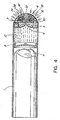
- FIG. 4 shows another embodiment of a pyrophoric flare according to the present invention wherein the rupturing disc 4, shell 1 and piston 8 are similar to those shown in the previous embodiments.
- the "pre-heating cavity" 30 is, in this embodiment, formed by a perforated dome 32 having a large number of perforations 38 open to the atmosphere.
- the dome 32 is attached to the exterior of the front cover assembly 3.
- the main nozzle duct 16 does not open directly towards the front of the dome 32 but feeds into two (branching) output ducts 18 and 18' in a central rearwardly facing hub 14 of dome 32, that hub having an axial rearwardly extending central opening between the branching ducts and an aligned opening of main duct 16 to which that central opening is connected.
- the branching ducts (18, 18') are at an angle to that axial extending central opening and open into the "pre-heating cavity" 30 formed between the dome 32 and front cover assembly 3.
- the interior of the "pre-heating cavity” 30 is filled with non-combustible fibers 34 (steel wool, asbestos, etc.) which act like a sponge for the pyrophoric liquid as it is ejected from the output ducts 18 and 18' and sprayed onto the fibers under pressure created by piston 8.
- the air flow surrounding the flare and the pressure produced by new pyrophoric liquid entering cavity 30 forces the pre-heated pyrophoric liquid in the cavity to exit through the small holes of the perforated dome 32 into the atmosphere where spontaneous combustion will occur.
- the flare burn times can be varied by changing the main and/or output ducts diameter, the number of output ducts and/or their orientation with respect to the main duct.
- This flare's IR signature can also be altered by changing the diameter and/or the number of holes in the perforated dome or by changing the pattern of the perforations.
- the IR signature furthermore, may also be varied by altering the density of fibers in the cavity or by removing those fibers entirely.
- a catalytic coating may be applied to the non-combustible fibers if the fibers are included in the "pre-heating cavity".
Landscapes
- Engineering & Computer Science (AREA)
- General Engineering & Computer Science (AREA)
- Aiming, Guidance, Guns With A Light Source, Armor, Camouflage, And Targets (AREA)
- Photometry And Measurement Of Optical Pulse Characteristics (AREA)
- Catching Or Destruction (AREA)
- Radiation Pyrometers (AREA)
- Special Spraying Apparatus (AREA)
- Spectrometry And Color Measurement (AREA)
- Filling Or Discharging Of Gas Storage Vessels (AREA)
- Radiation-Therapy Devices (AREA)
- Physical Water Treatments (AREA)
- Optical Filters (AREA)
- Agricultural Chemicals And Associated Chemicals (AREA)
Claims (10)
- Leuchtsatz mit einem Behälter für eine zündfähige Flüssigkeit (10), der eine äußere Hülle (1) mit einem Verschlussglied (3) enthält, das hermetisch mit der Hülle (1) verschlossen ist, um den Behälter auszubilden, wobei das Verschlussglied (3) eine zentrale Bruchscheibe (4) enthält, die bei einem vorbestimmten Druck bricht, mit einer Düsenkappe (5), die eine Düsenöffnung (6') enthält, die einer äußeren Oberfläche der Bruchscheibe (4) benachbart am Verschlussglied (3) angebracht ist, wobei die Düsenöffnung vor der äußeren Oberfläche liegt, wobei der Leuchtsatz einen Druckerzeugungsmechanismus (8) zum Ausüben von Druck auf die zündfähige Flüssigkeit (10) enthält, um die Bruchscheibe (5) zu brechen und die Flüssigkeit (10) durch die Düsenöffnung (6') auszustoßen,
dadurch gekennzeichnet, dass sich die Düsenöffnung (6') in eine Vorwärmkammer (20, 30) öffnet, die vor dem Verschlussglied (3) liegt, wobei die Vorwärmkammer (20, 30) durch ein Gehäuse (22, 32) ausgebildet wird, das die Düsenöffnung (6') umgibt, wobei das Gehäuse eine von der Düsenöffnung (6') beabstandete Außenfläche (24) enthält, die eine Anzahl von Löchern (28, 38) enthält, durch die Luft in die Vorwärmkammer (20, 30) eintreten kann, um die zündfähige Flüssigkeit zu zünden, und durch die die gezündete Flüssigkeit (10) in die Atmosphäre ausgestoßen werden kann. - Leuchtsatz wie in Anspruch 1 angegeben, bei dem das Gehäuse (20) durch eine Haube (22) ausgebildet wird, die sich von der Düsenkappe (5) her nach außen erstreckt und die die Düsenöffnung (6') umgibt, wobei die Außenfläche (24) eine mit Löchern versehene Scheibe ist, die in einer Öffnung an einem äußeren Rand der Haube (22) angeordnet ist.
- Leuchtsatz wie in Anspruch 2 angegeben, bei dem sich ein Flansch (26) am äußeren Rand der Haube (22) von der mit Löchern versehenen Scheibe (24) her nach vorne erstreckt.
- Leuchtsatz wie in Anspruch 1 angegeben, bei dem das Gehäuse eine Haube (22) ist, die durch einen rohrförmigen Vorsprung ausgebildet wird, der sich von der Düsenkappe (5) her nach außen erstreckt und die Düsenöffnung (6') umgibt, wobei die Außenfläche eine mit Löchern versehene Kuppel (32) ist, die in einer nach außen weisenden Öffnung des rohrförmigen Vorsprungs angeordnet ist.
- Leuchtsatz wie in Anspruch 4 angegeben, bei dem die Kuppel (32) eine konkave Innenfläche enthält, die der Düsenöffnung (6') gegenüberliegt, und ein Flansch an einem äußeren Rand des rohrförmigen Vorsprungs sich nach vorn zu einem inneren Rand der Kuppel erstreckt.
- Leuchtsatz wie in Anspruch 1 angegeben, bei dem das Gehäuse eine mit Löchern versehene Kuppel (32) ist, deren Rand eine Außenfläche des Verschlussgliedes (3) trifft.
- Leuchtsatz wie in einem der vorhergehenden Ansprüche angegeben, bei dem die Außenfläche (24) des Gehäuses eine zentrale, nach hinten vorstehende Nabe (14) mit einer Vielzahl von Düsenausgangskanälen (18, 18') enthält, die Öffnungen auf Oberflächen der Nabe (14) haben, wobei sich die Ausgangskanäle (18, 18') in eine sich nach hinten ersteckende zentrale Öffnung (16) der Nabe (14) öffnen, wobei die sich nach hinten ersteckende zentrale Öffnung (16) auf den Düsenkanal (6') in der Düsenkappe (5) ausgerichtet und damit verbunden ist.
- Leuchtsatz wie in einem der vorhergehenden Ansprüche angegeben, bei dem die Vorwärmkammer (20, 30) eine Menge von unbrennbaren Fasern (34) enthält.
- Leuchtsatz wie in Anspruch 8 angegeben, bei dem die unbrennbaren Fasern (34) Stahlwolle sind.
- Leuchtsatz wie in einem der vorhergehenden Ansprüche angegeben, der ein Täusch-Leuchtsatz für Infrarotsuch-Flugkörper ist, wobei die zündfähige Flüssigkeit (10) eine pyrophore Flüssigkeit ist.
Applications Claiming Priority (2)
| Application Number | Priority Date | Filing Date | Title |
|---|---|---|---|
| US08/932,626 US5866840A (en) | 1997-09-17 | 1997-09-17 | Nozzles for pyrophoric IR decoy flares |
| US932626 | 1997-09-17 |
Publications (3)
| Publication Number | Publication Date |
|---|---|
| EP0905472A2 EP0905472A2 (de) | 1999-03-31 |
| EP0905472A3 EP0905472A3 (de) | 2000-03-22 |
| EP0905472B1 true EP0905472B1 (de) | 2002-10-30 |
Family
ID=25462623
Family Applications (1)
| Application Number | Title | Priority Date | Filing Date |
|---|---|---|---|
| EP98306250A Expired - Lifetime EP0905472B1 (de) | 1997-09-17 | 1998-08-05 | Düse für pyrophorische, im Infrarotgebiet täuschende Leuchtsätze |
Country Status (10)
| Country | Link |
|---|---|
| US (1) | US5866840A (de) |
| EP (1) | EP0905472B1 (de) |
| AT (1) | ATE227017T1 (de) |
| AU (1) | AU732072B2 (de) |
| CA (1) | CA2237810C (de) |
| DE (1) | DE69809010T2 (de) |
| DK (1) | DK0905472T3 (de) |
| ES (1) | ES2185116T3 (de) |
| NO (1) | NO317748B1 (de) |
| PT (1) | PT905472E (de) |
Families Citing this family (14)
| Publication number | Priority date | Publication date | Assignee | Title |
|---|---|---|---|---|
| US6055909A (en) * | 1998-09-28 | 2000-05-02 | Raytheon Company | Electronically configurable towed decoy for dispensing infrared emitting flares |
| EP1342047B1 (de) * | 2000-12-13 | 2006-02-22 | The Secretary of State for Defence | Infrarot-leuchsatz |
| US7059250B1 (en) * | 2003-07-01 | 2006-06-13 | The United States Of America As Represented By The Secretary Of The Navy | Melted metal dispersal warhead |
| US7617776B1 (en) * | 2004-09-27 | 2009-11-17 | Diffraction, Ltd. | Selective emitting flare nanosensors |
| ATE527565T1 (de) | 2004-12-30 | 2011-10-15 | Proximion Fiber Systems Ab | Optischer koppler mit faser-bragg-gitter und fabry-perot-kavität entsprechende methode der nutzung |
| US7992496B2 (en) * | 2005-04-28 | 2011-08-09 | Alloy Surfaces Company, Inc. | Decoys for infra-red radiation seeking missiles and methods of producing and using the same |
| AU2006330065B2 (en) * | 2005-04-28 | 2011-12-01 | Alloy Surfaces Company, Inc. | Decoys for infra-red radiation seeking missiles and methods of producing and using the same |
| US7387060B1 (en) * | 2005-05-17 | 2008-06-17 | The United States Of America As Represented By The Secretary Of The Navy | Rocket exhaust defense system and method |
| WO2012037533A2 (en) | 2010-09-17 | 2012-03-22 | Dse, Inc. | Pyrophoric projectile |
| US9702670B2 (en) * | 2012-08-21 | 2017-07-11 | Omnitek Partners Llc | Countermeasure flares |
| US9593919B2 (en) * | 2013-04-12 | 2017-03-14 | The United States Of America As Represented By The Secretary Of The Navy | Method and apparatus for rapid deployment of a desirable material or chemical using a pyrophoric substrate |
| DE102013010266A1 (de) | 2013-06-18 | 2014-12-18 | Diehl Bgt Defence Gmbh & Co. Kg | Scheinzielwirkkörper mit einer pyrotechnischen Wirkmasse |
| DE102017114332B4 (de) * | 2017-06-28 | 2021-02-25 | Weco Pyrotechnische Fabrik Gmbh | Bühnenfeuerwerk |
| US10480783B2 (en) * | 2017-08-30 | 2019-11-19 | Lennox Industries Inc. | Positive pressure amplified gas-air valve for a low NOx premix combustion system |
Family Cites Families (10)
| Publication number | Priority date | Publication date | Assignee | Title |
|---|---|---|---|---|
| US3970003A (en) * | 1974-10-16 | 1976-07-20 | Avco Corporation | Pyrophoric flare |
| US3940605A (en) * | 1974-12-18 | 1976-02-24 | The United States Of America As Represented By The Secretary Of The Navy | Chemiluminescent marker apparatus |
| US5435224A (en) * | 1979-04-04 | 1995-07-25 | The United States Of America As Represented By The Secretary Of The Navy | Infrared decoy |
| FR2504670A1 (fr) * | 1981-04-23 | 1982-10-29 | Lacroix E | Eclairant pyrotechnique de grande puissance |
| CA1265988A (en) * | 1986-05-26 | 1990-02-20 | John Louis Halpin | Holder for flames of pyrophore-containing fuels in high-speed air |
| CA2027254C (en) * | 1990-10-10 | 1996-08-06 | John Louis Halpin | Flame-stabilized pyrophoric ir decoy flare |
| GB9120803D0 (en) * | 1991-10-01 | 1995-03-08 | Secr Defence | Pyrotechnic decoy flare |
| FR2694804B1 (fr) * | 1992-08-11 | 1994-09-16 | Poudres & Explosifs Ste Nale | Leurre stabilisée et propulsé, émettant dans l'infrarouge. |
| US5400712A (en) * | 1993-04-30 | 1995-03-28 | Alliant Techsystems Inc. | Decoy flare |
| US5631441A (en) * | 1996-04-02 | 1997-05-20 | Her Majesty The Queen In Right Of Canada, As Represented By The Minister Of National Defence Of Her Majesty's Canadian Government | XDM pyrophoric countermeasure flare |
-
1997
- 1997-09-17 US US08/932,626 patent/US5866840A/en not_active Expired - Fee Related
-
1998
- 1998-05-15 CA CA002237810A patent/CA2237810C/en not_active Expired - Fee Related
- 1998-08-03 AU AU78670/98A patent/AU732072B2/en not_active Ceased
- 1998-08-05 ES ES98306250T patent/ES2185116T3/es not_active Expired - Lifetime
- 1998-08-05 DK DK98306250T patent/DK0905472T3/da active
- 1998-08-05 PT PT98306250T patent/PT905472E/pt unknown
- 1998-08-05 DE DE69809010T patent/DE69809010T2/de not_active Expired - Fee Related
- 1998-08-05 EP EP98306250A patent/EP0905472B1/de not_active Expired - Lifetime
- 1998-08-05 AT AT98306250T patent/ATE227017T1/de not_active IP Right Cessation
- 1998-09-16 NO NO19984285A patent/NO317748B1/no unknown
Also Published As
| Publication number | Publication date |
|---|---|
| ATE227017T1 (de) | 2002-11-15 |
| NO984285L (no) | 1999-03-18 |
| PT905472E (pt) | 2003-03-31 |
| EP0905472A2 (de) | 1999-03-31 |
| DE69809010T2 (de) | 2003-03-20 |
| CA2237810A1 (en) | 1999-03-17 |
| US5866840A (en) | 1999-02-02 |
| AU7867098A (en) | 1999-04-01 |
| ES2185116T3 (es) | 2003-04-16 |
| EP0905472A3 (de) | 2000-03-22 |
| DK0905472T3 (da) | 2002-11-25 |
| DE69809010D1 (de) | 2002-12-05 |
| AU732072B2 (en) | 2001-04-12 |
| NO317748B1 (no) | 2004-12-13 |
| NO984285D0 (no) | 1998-09-16 |
| CA2237810C (en) | 2003-07-29 |
Similar Documents
| Publication | Publication Date | Title |
|---|---|---|
| EP0905472B1 (de) | Düse für pyrophorische, im Infrarotgebiet täuschende Leuchtsätze | |
| US5631441A (en) | XDM pyrophoric countermeasure flare | |
| US5074216A (en) | Infrared signature enhancement decoy | |
| US5952601A (en) | Recoilless and gas-free projectile propulsion | |
| US5390605A (en) | Stabilized and propelled decoy, emitting in the infra-red | |
| KR20040015333A (ko) | 진화방법 및 진화장치 | |
| US4171669A (en) | Decoy flare | |
| US20090223402A1 (en) | Pyrotechnic systems and associated methods | |
| US5136950A (en) | Flame-stabilized pyrophoric IR decoy flare | |
| GB2370625A (en) | A piece of ammunition for generating a fog | |
| WO2000034731A3 (en) | Gas generating eject motor | |
| US5929369A (en) | Assembly for the optical marking of the flight path of a projectile or aeroplane accelerated by a power unit | |
| US5099764A (en) | Propulsion unit fireable from an enclosure | |
| US6955125B1 (en) | Practice projectile with smoke signature | |
| US5157219A (en) | Primers | |
| US3670657A (en) | Signal flare | |
| US5610364A (en) | Nozzle plug for plume enhancement in a kinematic flare | |
| US5654522A (en) | Plume enhancement nozzle for achieving flare rotation | |
| RU68117U1 (ru) | Дымовая граната (варианты) | |
| GB1577901A (en) | Infra-red radiation device supply arrangement | |
| US3611936A (en) | Pyrotechnic tracer | |
| US11965722B2 (en) | Non-incendiary tracers | |
| Withey | Infrared countermeasure flares | |
| RU2321816C2 (ru) | Способ защиты объектов бронетанковой техники и устройство для его осуществления | |
| RU2060442C1 (ru) | Патрон специального назначения |
Legal Events
| Date | Code | Title | Description |
|---|---|---|---|
| PUAI | Public reference made under article 153(3) epc to a published international application that has entered the european phase |
Free format text: ORIGINAL CODE: 0009012 |
|
| AK | Designated contracting states |
Kind code of ref document: A2 Designated state(s): AT BE DE DK ES FI FR GB GR NL PT |
|
| AX | Request for extension of the european patent |
Free format text: AL;LT;LV;MK;RO;SI |
|
| PUAL | Search report despatched |
Free format text: ORIGINAL CODE: 0009013 |
|
| AK | Designated contracting states |
Kind code of ref document: A3 Designated state(s): AT BE CH CY DE DK ES FI FR GB GR IE IT LI LU MC NL PT SE |
|
| AX | Request for extension of the european patent |
Free format text: AL;LT;LV;MK;RO;SI |
|
| 17P | Request for examination filed |
Effective date: 20000508 |
|
| AKX | Designation fees paid |
Free format text: AT BE DE DK ES FI FR GB GR NL PT |
|
| GRAG | Despatch of communication of intention to grant |
Free format text: ORIGINAL CODE: EPIDOS AGRA |
|
| GRAG | Despatch of communication of intention to grant |
Free format text: ORIGINAL CODE: EPIDOS AGRA |
|
| 17Q | First examination report despatched |
Effective date: 20011217 |
|
| GRAG | Despatch of communication of intention to grant |
Free format text: ORIGINAL CODE: EPIDOS AGRA |
|
| GRAH | Despatch of communication of intention to grant a patent |
Free format text: ORIGINAL CODE: EPIDOS IGRA |
|
| GRAH | Despatch of communication of intention to grant a patent |
Free format text: ORIGINAL CODE: EPIDOS IGRA |
|
| GRAA | (expected) grant |
Free format text: ORIGINAL CODE: 0009210 |
|
| AK | Designated contracting states |
Kind code of ref document: B1 Designated state(s): AT BE DE DK ES FI FR GB GR NL PT |
|
| REF | Corresponds to: |
Ref document number: 227017 Country of ref document: AT Date of ref document: 20021115 Kind code of ref document: T |
|
| REG | Reference to a national code |
Ref country code: GB Ref legal event code: FG4D |
|
| REG | Reference to a national code |
Ref country code: DK Ref legal event code: T3 |
|
| REF | Corresponds to: |
Ref document number: 69809010 Country of ref document: DE Date of ref document: 20021205 |
|
| REG | Reference to a national code |
Ref country code: GR Ref legal event code: EP Ref document number: 20030400173 Country of ref document: GR |
|
| REG | Reference to a national code |
Ref country code: PT Ref legal event code: SC4A Free format text: AVAILABILITY OF NATIONAL TRANSLATION Effective date: 20030121 |
|
| REG | Reference to a national code |
Ref country code: ES Ref legal event code: FG2A Ref document number: 2185116 Country of ref document: ES Kind code of ref document: T3 |
|
| ET | Fr: translation filed | ||
| PLBE | No opposition filed within time limit |
Free format text: ORIGINAL CODE: 0009261 |
|
| STAA | Information on the status of an ep patent application or granted ep patent |
Free format text: STATUS: NO OPPOSITION FILED WITHIN TIME LIMIT |
|
| 26N | No opposition filed |
Effective date: 20030731 |
|
| PGFP | Annual fee paid to national office [announced via postgrant information from national office to epo] |
Ref country code: DE Payment date: 20070820 Year of fee payment: 10 |
|
| PGFP | Annual fee paid to national office [announced via postgrant information from national office to epo] |
Ref country code: DK Payment date: 20070827 Year of fee payment: 10 |
|
| PGFP | Annual fee paid to national office [announced via postgrant information from national office to epo] |
Ref country code: ES Payment date: 20070927 Year of fee payment: 10 |
|
| PGFP | Annual fee paid to national office [announced via postgrant information from national office to epo] |
Ref country code: FI Payment date: 20070807 Year of fee payment: 10 Ref country code: AT Payment date: 20070731 Year of fee payment: 10 |
|
| PGFP | Annual fee paid to national office [announced via postgrant information from national office to epo] |
Ref country code: GB Payment date: 20070824 Year of fee payment: 10 |
|
| PGFP | Annual fee paid to national office [announced via postgrant information from national office to epo] |
Ref country code: NL Payment date: 20070831 Year of fee payment: 10 Ref country code: BE Payment date: 20070726 Year of fee payment: 10 |
|
| PGFP | Annual fee paid to national office [announced via postgrant information from national office to epo] |
Ref country code: FR Payment date: 20070817 Year of fee payment: 10 |
|
| PGFP | Annual fee paid to national office [announced via postgrant information from national office to epo] |
Ref country code: GR Payment date: 20070730 Year of fee payment: 10 |
|
| REG | Reference to a national code |
Ref country code: PT Ref legal event code: MM4A Free format text: LAPSE DUE TO NON-PAYMENT OF FEES Effective date: 20090205 |
|
| REG | Reference to a national code |
Ref country code: DK Ref legal event code: EBP |
|
| GBPC | Gb: european patent ceased through non-payment of renewal fee |
Effective date: 20080805 |
|
| PG25 | Lapsed in a contracting state [announced via postgrant information from national office to epo] |
Ref country code: AT Free format text: LAPSE BECAUSE OF NON-PAYMENT OF DUE FEES Effective date: 20080805 |
|
| NLV4 | Nl: lapsed or anulled due to non-payment of the annual fee |
Effective date: 20090301 |
|
| PG25 | Lapsed in a contracting state [announced via postgrant information from national office to epo] |
Ref country code: PT Free format text: LAPSE BECAUSE OF NON-PAYMENT OF DUE FEES Effective date: 20090205 Ref country code: NL Free format text: LAPSE BECAUSE OF NON-PAYMENT OF DUE FEES Effective date: 20090301 Ref country code: FI Free format text: LAPSE BECAUSE OF NON-PAYMENT OF DUE FEES Effective date: 20080805 |
|
| REG | Reference to a national code |
Ref country code: FR Ref legal event code: ST Effective date: 20090430 |
|
| PG25 | Lapsed in a contracting state [announced via postgrant information from national office to epo] |
Ref country code: GR Free format text: LAPSE BECAUSE OF NON-PAYMENT OF DUE FEES Effective date: 20090304 |
|
| PG25 | Lapsed in a contracting state [announced via postgrant information from national office to epo] |
Ref country code: DK Free format text: LAPSE BECAUSE OF NON-PAYMENT OF DUE FEES Effective date: 20080831 Ref country code: BE Free format text: LAPSE BECAUSE OF NON-PAYMENT OF DUE FEES Effective date: 20080831 |
|
| PG25 | Lapsed in a contracting state [announced via postgrant information from national office to epo] |
Ref country code: FR Free format text: LAPSE BECAUSE OF NON-PAYMENT OF DUE FEES Effective date: 20080901 Ref country code: DE Free format text: LAPSE BECAUSE OF NON-PAYMENT OF DUE FEES Effective date: 20090303 |
|
| REG | Reference to a national code |
Ref country code: ES Ref legal event code: FD2A Effective date: 20080806 |
|
| PG25 | Lapsed in a contracting state [announced via postgrant information from national office to epo] |
Ref country code: GB Free format text: LAPSE BECAUSE OF NON-PAYMENT OF DUE FEES Effective date: 20080805 |
|
| PGFP | Annual fee paid to national office [announced via postgrant information from national office to epo] |
Ref country code: PT Payment date: 20070725 Year of fee payment: 10 |
|
| PG25 | Lapsed in a contracting state [announced via postgrant information from national office to epo] |
Ref country code: ES Free format text: LAPSE BECAUSE OF NON-PAYMENT OF DUE FEES Effective date: 20080806 |