EP0905460A2 - Kühlschrank - Google Patents
Kühlschrank Download PDFInfo
- Publication number
- EP0905460A2 EP0905460A2 EP98306687A EP98306687A EP0905460A2 EP 0905460 A2 EP0905460 A2 EP 0905460A2 EP 98306687 A EP98306687 A EP 98306687A EP 98306687 A EP98306687 A EP 98306687A EP 0905460 A2 EP0905460 A2 EP 0905460A2
- Authority
- EP
- European Patent Office
- Prior art keywords
- cool air
- refrigerator
- coupling
- tube
- dispersing
- Prior art date
- Legal status (The legal status is an assumption and is not a legal conclusion. Google has not performed a legal analysis and makes no representation as to the accuracy of the status listed.)
- Withdrawn
Links
Images


Classifications
-
- F—MECHANICAL ENGINEERING; LIGHTING; HEATING; WEAPONS; BLASTING
- F25—REFRIGERATION OR COOLING; COMBINED HEATING AND REFRIGERATION SYSTEMS; HEAT PUMP SYSTEMS; MANUFACTURE OR STORAGE OF ICE; LIQUEFACTION SOLIDIFICATION OF GASES
- F25D—REFRIGERATORS; COLD ROOMS; ICE-BOXES; COOLING OR FREEZING APPARATUS NOT OTHERWISE PROVIDED FOR
- F25D17/00—Arrangements for circulating cooling fluids; Arrangements for circulating gas, e.g. air, within refrigerated spaces
-
- F—MECHANICAL ENGINEERING; LIGHTING; HEATING; WEAPONS; BLASTING
- F24—HEATING; RANGES; VENTILATING
- F24F—AIR-CONDITIONING; AIR-HUMIDIFICATION; VENTILATION; USE OF AIR CURRENTS FOR SCREENING
- F24F13/00—Details common to, or for air-conditioning, air-humidification, ventilation or use of air currents for screening
- F24F13/02—Ducting arrangements
- F24F13/06—Outlets for directing or distributing air into rooms or spaces, e.g. ceiling air diffuser
- F24F13/075—Outlets for directing or distributing air into rooms or spaces, e.g. ceiling air diffuser having parallel rods or lamellae directing the outflow, e.g. the rods or lamellae being individually adjustable
-
- F—MECHANICAL ENGINEERING; LIGHTING; HEATING; WEAPONS; BLASTING
- F25—REFRIGERATION OR COOLING; COMBINED HEATING AND REFRIGERATION SYSTEMS; HEAT PUMP SYSTEMS; MANUFACTURE OR STORAGE OF ICE; LIQUEFACTION SOLIDIFICATION OF GASES
- F25D—REFRIGERATORS; COLD ROOMS; ICE-BOXES; COOLING OR FREEZING APPARATUS NOT OTHERWISE PROVIDED FOR
- F25D17/00—Arrangements for circulating cooling fluids; Arrangements for circulating gas, e.g. air, within refrigerated spaces
- F25D17/04—Arrangements for circulating cooling fluids; Arrangements for circulating gas, e.g. air, within refrigerated spaces for circulating air, e.g. by convection
- F25D17/042—Air treating means within refrigerated spaces
- F25D17/045—Air flow control arrangements
-
- F—MECHANICAL ENGINEERING; LIGHTING; HEATING; WEAPONS; BLASTING
- F25—REFRIGERATION OR COOLING; COMBINED HEATING AND REFRIGERATION SYSTEMS; HEAT PUMP SYSTEMS; MANUFACTURE OR STORAGE OF ICE; LIQUEFACTION SOLIDIFICATION OF GASES
- F25D—REFRIGERATORS; COLD ROOMS; ICE-BOXES; COOLING OR FREEZING APPARATUS NOT OTHERWISE PROVIDED FOR
- F25D17/00—Arrangements for circulating cooling fluids; Arrangements for circulating gas, e.g. air, within refrigerated spaces
- F25D17/04—Arrangements for circulating cooling fluids; Arrangements for circulating gas, e.g. air, within refrigerated spaces for circulating air, e.g. by convection
- F25D17/06—Arrangements for circulating cooling fluids; Arrangements for circulating gas, e.g. air, within refrigerated spaces for circulating air, e.g. by convection by forced circulation
- F25D17/062—Arrangements for circulating cooling fluids; Arrangements for circulating gas, e.g. air, within refrigerated spaces for circulating air, e.g. by convection by forced circulation in household refrigerators
- F25D17/065—Arrangements for circulating cooling fluids; Arrangements for circulating gas, e.g. air, within refrigerated spaces for circulating air, e.g. by convection by forced circulation in household refrigerators with compartments at different temperatures
-
- F—MECHANICAL ENGINEERING; LIGHTING; HEATING; WEAPONS; BLASTING
- F24—HEATING; RANGES; VENTILATING
- F24F—AIR-CONDITIONING; AIR-HUMIDIFICATION; VENTILATION; USE OF AIR CURRENTS FOR SCREENING
- F24F11/00—Control or safety arrangements
- F24F11/70—Control systems characterised by their outputs; Constructional details thereof
- F24F11/72—Control systems characterised by their outputs; Constructional details thereof for controlling the supply of treated air, e.g. its pressure
- F24F11/79—Control systems characterised by their outputs; Constructional details thereof for controlling the supply of treated air, e.g. its pressure for controlling the direction of the supplied air
-
- F—MECHANICAL ENGINEERING; LIGHTING; HEATING; WEAPONS; BLASTING
- F24—HEATING; RANGES; VENTILATING
- F24F—AIR-CONDITIONING; AIR-HUMIDIFICATION; VENTILATION; USE OF AIR CURRENTS FOR SCREENING
- F24F13/00—Details common to, or for air-conditioning, air-humidification, ventilation or use of air currents for screening
- F24F13/08—Air-flow control members, e.g. louvres, grilles, flaps or guide plates
- F24F13/10—Air-flow control members, e.g. louvres, grilles, flaps or guide plates movable, e.g. dampers
- F24F13/14—Air-flow control members, e.g. louvres, grilles, flaps or guide plates movable, e.g. dampers built up of tilting members, e.g. louvre
- F24F13/1426—Air-flow control members, e.g. louvres, grilles, flaps or guide plates movable, e.g. dampers built up of tilting members, e.g. louvre characterised by actuating means
- F24F2013/1473—Air-flow control members, e.g. louvres, grilles, flaps or guide plates movable, e.g. dampers built up of tilting members, e.g. louvre characterised by actuating means with cams or levers
-
- F—MECHANICAL ENGINEERING; LIGHTING; HEATING; WEAPONS; BLASTING
- F24—HEATING; RANGES; VENTILATING
- F24F—AIR-CONDITIONING; AIR-HUMIDIFICATION; VENTILATION; USE OF AIR CURRENTS FOR SCREENING
- F24F2221/00—Details or features not otherwise provided for
- F24F2221/48—HVAC for a wine cellar
-
- F—MECHANICAL ENGINEERING; LIGHTING; HEATING; WEAPONS; BLASTING
- F25—REFRIGERATION OR COOLING; COMBINED HEATING AND REFRIGERATION SYSTEMS; HEAT PUMP SYSTEMS; MANUFACTURE OR STORAGE OF ICE; LIQUEFACTION SOLIDIFICATION OF GASES
- F25D—REFRIGERATORS; COLD ROOMS; ICE-BOXES; COOLING OR FREEZING APPARATUS NOT OTHERWISE PROVIDED FOR
- F25D2317/00—Details or arrangements for circulating cooling fluids; Details or arrangements for circulating gas, e.g. air, within refrigerated spaces, not provided for in other groups of this subclass
- F25D2317/06—Details or arrangements for circulating cooling fluids; Details or arrangements for circulating gas, e.g. air, within refrigerated spaces, not provided for in other groups of this subclass with forced air circulation
- F25D2317/065—Details or arrangements for circulating cooling fluids; Details or arrangements for circulating gas, e.g. air, within refrigerated spaces, not provided for in other groups of this subclass with forced air circulation characterised by the air return
- F25D2317/0653—Details or arrangements for circulating cooling fluids; Details or arrangements for circulating gas, e.g. air, within refrigerated spaces, not provided for in other groups of this subclass with forced air circulation characterised by the air return through the mullion
-
- F—MECHANICAL ENGINEERING; LIGHTING; HEATING; WEAPONS; BLASTING
- F25—REFRIGERATION OR COOLING; COMBINED HEATING AND REFRIGERATION SYSTEMS; HEAT PUMP SYSTEMS; MANUFACTURE OR STORAGE OF ICE; LIQUEFACTION SOLIDIFICATION OF GASES
- F25D—REFRIGERATORS; COLD ROOMS; ICE-BOXES; COOLING OR FREEZING APPARATUS NOT OTHERWISE PROVIDED FOR
- F25D2317/00—Details or arrangements for circulating cooling fluids; Details or arrangements for circulating gas, e.g. air, within refrigerated spaces, not provided for in other groups of this subclass
- F25D2317/06—Details or arrangements for circulating cooling fluids; Details or arrangements for circulating gas, e.g. air, within refrigerated spaces, not provided for in other groups of this subclass with forced air circulation
- F25D2317/067—Details or arrangements for circulating cooling fluids; Details or arrangements for circulating gas, e.g. air, within refrigerated spaces, not provided for in other groups of this subclass with forced air circulation characterised by air ducts
- F25D2317/0672—Outlet ducts
-
- F—MECHANICAL ENGINEERING; LIGHTING; HEATING; WEAPONS; BLASTING
- F25—REFRIGERATION OR COOLING; COMBINED HEATING AND REFRIGERATION SYSTEMS; HEAT PUMP SYSTEMS; MANUFACTURE OR STORAGE OF ICE; LIQUEFACTION SOLIDIFICATION OF GASES
- F25D—REFRIGERATORS; COLD ROOMS; ICE-BOXES; COOLING OR FREEZING APPARATUS NOT OTHERWISE PROVIDED FOR
- F25D2400/00—General features of, or devices for refrigerators, cold rooms, ice-boxes, or for cooling or freezing apparatus not covered by any other subclass
- F25D2400/04—Refrigerators with a horizontal mullion
Definitions
- the present invention relates to a refrigerator comprising a cooling compartment, a heat pump, means for driving cool air generated by the heat pump through an aperture into the cooling compartment, and flow directing means associated with the aperture for directing said cool air.
- a refrigerator has a freezing compartment and a cooling compartment separated by a partition wall that are cooled by a cooling system, comprising a condenser, a compressor and an evaporator, to temperatures below and above freezing respectively, to maintain the freshness of food and beverages stored in the refrigerator.
- a cooling system comprising a condenser, a compressor and an evaporator
- a conventional refrigerator is illustrated in Figure 1 and includes a housing containing a freezing and a cooling compartment 2,3.
- An evaporator 4 is mounted to the rear of the freezing compartment 2 for generating cool air which is driven by a fan 5 along ducts 2a,3a into the freezing and cooling compartments 2,3.
- a cool air dispersing system 6 having a cool air dispersing device 7 for dispersing cool air within the refrigerating compartment 3 is disposed in the duct 3a and a motor 6a is provided for rotating the cool air dispersing device 7.
- a cool air dispersing device 7 of a conventional air dispersing system is illustrated in Figure 2 and comprises a plurality of air guides 8 disposed on a rotatable shaft 9.
- the cool air dispersing device 7 is divided into upper and lower parts 7a,7b to enable the guides 8 on each part 7a,7b to be oriented at different angles with respect to each other and effectively disperse the cool air.
- the upper and lower parts 7a,7b are coupled together by means of a projection extending from the end of the rotating shaft 9 of the upper part 7a which locates in a recess in the top of the rotating shaft 9 of the lower part 7b.
- a problem with conventional refrigerators is that the air dispersing system directs and supplies the cool air only to a particular area of the cooling compartment whilst other areas are less well served. Consequently, a uniform temperature is not maintained throughout the cooling compartment. This problem is particularly prevalent in large refrigerators and, in particular, when a large quantity of food is located on the uppermost or lowermost shelves of the cooling compartment.
- a refrigerator according to the present invention is characterised in that the flow directing means includes a first means for directing air flow in the vertical plane and second means for directing air flow in the horizontal plane, wherein the first means is drivingly coupled to the second means so as to be driven thereby.
- the flow directing means comprises a blade or plurality of horizontal blades reciprocally pivotable about respective horizontal axes.
- the refrigerator includes rotatably mounted cam means, and cam follower means for driving the or each blade during rotation of the cam means.
- the second means preferably includes a plurality of vane surfaces on a shaft mounted for rotation about a vertical axis, the cam means being disposed on the shaft.
- the rotatably mounted vane surfaces are partially surrounded by the or each horizontal blade, the or each horizontal blade having a cutout to receive the vane surfaces.
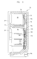
- a refrigerator includes a cabinet 10, a freezing and a cooling compartment 20,30 formed within the cabinet 10 and separated by a partition wall 11.
- the compartments 20,30 are provided with respective doors 21,31.
- a cooling system comprising a compressor 12a, a condenser (not shown) and an evaporator 12 for generating cool air is mounted in the cabinet 10.
- the cool air generated by the evaporator 12 is supplied into the freezing and cooling compartment 20,30 by a fan 13 disposed above the evaporator 12.
- Respective ducts 14a,14b are provided for guiding the cool air into the freezing and refrigerating compartments 20 and 30.
- An inlet hole 15 is formed in the duct 14a through which cool air can pass into the freezing compartment 20 and a cool air dispersing system 100 for uniformly dispersing cool air throughout the cooling compartment 30 is provided on the duct 14b.
- a plurality of outlet holes 141 are formed in an outlet plate 140 disposed in front of the cool air dispersing system 100 through which cool air can pass into the cooling compartment 30.
- the cool air dispersing system 100 comprises a first cool air dispersing device 110 for dispersing cool air in a substantially horizontal direction, a motor 120 for rotatably driving the first cool air dispersing device 110, and a second cool air dispersing device 130 for dispersing cool air in a substantially vertical direction.
- the second cool air dispersing device 130 is operated by means of a cam member and cam follower arrangement which converts rotation of the first air dispersing device 130 into reciprocal motion, and which will be explained in more detail hereafter.
- the first cool air dispersing device 100 is divided into upper and lower parts 110a, 110b each comprising a dispersing plate 112a for dispersing cool air in a horizontal direction, a plurality of vanes 112b arranged on opposite sides of the dispersing plate 112a oriented at different angles to each other, and a shaft 111 for rotatably mounting the device formed on opposite ends of the dispersing plate 112a.
- the upper end of rotatable shaft 111 of the upper part 110a is connected to the motor 120, and the rotatable shaft 111 of the lower device 110a is coupled at its lower end to the second cool air dispersing device 130.
- First and second coupling tubes 113a, 113b are respectively provided on the lower end of the shaft 111 of the upper part 110a and an upper end of shaft 111 of the lower part 110b.
- the second coupling tube 113b has a sloped upper edge and an exterior circumferential shoulder 115a is formed around its edge.
- the shaft 111 of the upper part 110a extends into the second coupling tube 113b.
- the first coupling tube 113a has a sloped upper edge corresponding to the sloped upper edge of the second coupling tube 113b and defines an interior circumferential shoulder portion 115a in which the exterior circumferential shoulder 115a locates to couple the first and second coupling tubes 113a,113b together.
- the depth d1 of the interior circumferential shoulder portion 115b is less than the depth d2 of the exterior circumferential shoulder portion 115a so that not all of the exterior circumferential shoulder portion 115a is received within the interior circumferential shoulder portion 115b leaving a sloped groove 114 between the coupled upper and lower coupling tubes 113a,113b.
- the coupled upper and lower coupling tubes together form a cam member.
- coupling means are provided and comprise a projection 116a extending from the end of the shaft 111 extending into the second coupling tube 113b and a notch 116b formed in the end of the shaft 111 extending into the first coupling tube 113a.
- projection 116a is inserted into the notch 116b.
- the projection 116b is X-shaped.
- the second cool air dispersing device 130 is disposed in front of the horizontal cool air dispersing device 110 and comprises a support member 131 having opposite opened ends through which cool air can pass, a plurality of blades 132 pivotably coupled to the support member 131 and an operating member 133 pivotally supporting the blades 132.
- Each blade 132 is made of a semi-circular plate and has a pair of first rollers 132a pivotally coupled to holders 131a on support member 131, and a second roller 132b pivotally coupled to a holder 133b on the operating bar 133.
- the blades 132 pivot about horizontal axis extending through each pair of rollers 132a in response to rotation of the motor 120.
- the device for converting the rotational motion of the first air dispersing device 110 into reciprocal motion which comprises a projection or cam follower 133a extending from the operating bar 133 and which is received in the sloped groove 114 so that when the first cool air dispersing device 110 is rotating, the projection 133a travels along the sloped groove 144 causing the operating bar 133 to reciprocate. Consequently, the blades 132 coupled to the operating bar 133 pivot to disperse the cool air in a vertical direction.
- the alternative first cool air dispersing device 210 is divided into upper and lower parts 210a and 210b as with the first embodiment, and each part 210a,210b comprises a dispersing plate 212a, a plurality of vanes 212b arranged on opposite sides of the dispersing plate 112a, and a rotating shaft 111 formed on opposite ends of the dispersing plate 112a.
- a second coupling tube 213b is disposed on an upper end of the lower part 219b, and has an upper edge which defines an exterior circumferential shoulder portion 215a.
- the overall diameter of the shoulder portion 215a of the second coupling tube 213b is less than the overall diameter of a first coupling tube 213a which depends from the lower end of the upper part and has a correspondingly sloped edge such that when the two coupling tubes are brought together the shoulder portion 215a is received within the first coupling tube 213a, thereby coupling the upper and lower parts 210a,110b together and leaving a sloped groove 214 therebetween, as with the first embodiment.
- the coupled coupling tubes together form a cam member.
- the coupling means comprises a seat 216 disposed on the inner lower surface of the second coupling tube 213b, and a projection 217a extending from the seat.
- the projection 217a is inserted into a tube 217b formed inside the first coupling tube 213a.
- a plurality of hooks 218 extend from the tip of the projection 217a and are received in a groove 219 in the end of the fixing tube 217b.
- the lower end of the fixing tube 217b contacts the upper end of the seat 216.
- the projection 217a is insertable into the tube 217b such that the shoulder 215a is not fully received within the first coupling tube 213a, thereby defining a sloping groove 214 between the first and second coupling tubes 213a,213b.
- the projection or cam follower 133a extending from the operating bar 133 of the second cool air dispersing device 130 is received in the sloped groove 214 so that rotation of the first air dispersing device 210 causes the projection to travel along the groove 214 and reciprocate the operating bar to cause the blades to pivot.
- a portion of cool air generated by the evaporator 12 is directed by fan 13 to the freezing compartment, and the remainder is directed to the cool air dispersing system 100.
- the cool air directed to the cool air dispersing system 100 is forced inside the refrigerating compartment by the first and second cool air dispersing devices 110,130.
- the operating bar reciprocates and causes the blades 132 connected to the support member 131 and the operating bar 133 to pivot up and down thereby assisting in the dispersal of the cool air.
Landscapes
- Engineering & Computer Science (AREA)
- Chemical & Material Sciences (AREA)
- Combustion & Propulsion (AREA)
- Mechanical Engineering (AREA)
- General Engineering & Computer Science (AREA)
- Physics & Mathematics (AREA)
- Thermal Sciences (AREA)
- Cold Air Circulating Systems And Constructional Details In Refrigerators (AREA)
- Structures Of Non-Positive Displacement Pumps (AREA)
Applications Claiming Priority (8)
| Application Number | Priority Date | Filing Date | Title |
|---|---|---|---|
| KR9749451 | 1997-09-27 | ||
| KR9749450 | 1997-09-27 | ||
| KR1019970049451A KR19990027079A (ko) | 1997-09-27 | 1997-09-27 | 냉장고의 냉기토출부 |
| KR2019970026846U KR19990013539U (ko) | 1997-09-27 | 1997-09-27 | 냉장고의 냉기토출부 |
| KR1019970049450A KR19990027078A (ko) | 1997-09-27 | 1997-09-27 | 냉장고의 냉기토출부 |
| KR2019970026845U KR19990013538U (ko) | 1997-09-27 | 1997-09-27 | 냉장고의 냉기토출부 |
| KR9726846U | 1997-09-27 | ||
| KR9726845U | 1997-09-27 |
Publications (2)
| Publication Number | Publication Date |
|---|---|
| EP0905460A2 true EP0905460A2 (de) | 1999-03-31 |
| EP0905460A3 EP0905460A3 (de) | 1999-10-20 |
Family
ID=27483209
Family Applications (1)
| Application Number | Title | Priority Date | Filing Date |
|---|---|---|---|
| EP98306687A Withdrawn EP0905460A3 (de) | 1997-09-27 | 1998-08-20 | Kühlschrank |
Country Status (5)
| Country | Link |
|---|---|
| US (1) | US6006539A (de) |
| EP (1) | EP0905460A3 (de) |
| JP (1) | JP3037274B2 (de) |
| KR (1) | KR100286169B1 (de) |
| CN (1) | CN1138956C (de) |
Cited By (1)
| Publication number | Priority date | Publication date | Assignee | Title |
|---|---|---|---|---|
| RU180809U1 (ru) * | 2017-11-07 | 2018-06-22 | федеральное государственное бюджетное образовательное учреждение высшего образования "Волгоградский государственный аграрный университет" (ФГБОУ ВО Волгоградский ГАУ) | Тепловой насос |
Families Citing this family (6)
| Publication number | Priority date | Publication date | Assignee | Title |
|---|---|---|---|---|
| US6268618B1 (en) * | 1997-05-08 | 2001-07-31 | Showa Denko K.K. | Electrode for light-emitting semiconductor devices and method of producing the electrode |
| KR20070093633A (ko) * | 2006-03-14 | 2007-09-19 | 엘지전자 주식회사 | 음료수용 냉장고 |
| JP5787837B2 (ja) * | 2012-07-23 | 2015-09-30 | 三菱電機株式会社 | 冷蔵庫 |
| CN102914115A (zh) * | 2012-11-20 | 2013-02-06 | 合肥美菱股份有限公司 | 一种风冷直冷相结合的冰箱 |
| KR102440430B1 (ko) * | 2015-12-24 | 2022-09-07 | 주식회사 위니아 | 에어컨 |
| CN107588589B (zh) * | 2017-09-22 | 2019-12-27 | 合肥华凌股份有限公司 | 用于制冷设备的控风装置和具有其的制冷设备 |
Family Cites Families (12)
| Publication number | Priority date | Publication date | Assignee | Title |
|---|---|---|---|---|
| FR2457190A1 (fr) * | 1979-05-22 | 1980-12-19 | Renault | Aerateur a ailettes orientables pour vehicule automobile |
| US4653386A (en) * | 1984-11-20 | 1987-03-31 | Toyota Jidosha Kabushiki Kaisha | Wind direction adjusting mechanism for air conditioner |
| KR0160424B1 (ko) * | 1994-06-01 | 1999-01-15 | 윤종용 | 냉장고 |
| TW326488B (en) * | 1994-06-02 | 1998-02-11 | Samsung Electronics Co Ltd | Refrigerator |
| KR0160423B1 (ko) * | 1994-07-19 | 1999-01-15 | 윤종용 | 냉장고의 냉기순환장치 |
| KR0170697B1 (ko) * | 1994-12-10 | 1999-03-20 | 윤종용 | 냉장고 및 냉기 토출 방향 제어에 의한 그 온도 제어 방법 |
| KR200143520Y1 (ko) * | 1995-08-19 | 1999-06-15 | 윤종용 | 냉장고 |
| KR0152148B1 (ko) * | 1995-08-19 | 1998-11-02 | 김광호 | 냉장고 |
| KR0152149B1 (ko) * | 1995-08-19 | 1998-11-02 | 김광호 | 냉장고 |
| KR0162412B1 (ko) * | 1995-10-13 | 1999-02-18 | 구자홍 | 냉장고의 신규 부하 집중 냉각장치 |
| JP2993412B2 (ja) * | 1995-11-20 | 1999-12-20 | 三菱電機株式会社 | 吹出口及び該吹出口を備えた空気調和装置 |
| KR100222942B1 (ko) * | 1997-07-31 | 1999-10-01 | 윤종용 | 냉기분배장치를 갖는 냉장고 |
-
1998
- 1998-07-15 KR KR1019980028753A patent/KR100286169B1/ko not_active Expired - Fee Related
- 1998-07-30 JP JP10216150A patent/JP3037274B2/ja not_active Expired - Fee Related
- 1998-08-04 US US09/129,182 patent/US6006539A/en not_active Expired - Fee Related
- 1998-08-18 CN CNB981183891A patent/CN1138956C/zh not_active Expired - Fee Related
- 1998-08-20 EP EP98306687A patent/EP0905460A3/de not_active Withdrawn
Cited By (1)
| Publication number | Priority date | Publication date | Assignee | Title |
|---|---|---|---|---|
| RU180809U1 (ru) * | 2017-11-07 | 2018-06-22 | федеральное государственное бюджетное образовательное учреждение высшего образования "Волгоградский государственный аграрный университет" (ФГБОУ ВО Волгоградский ГАУ) | Тепловой насос |
Also Published As
| Publication number | Publication date |
|---|---|
| CN1213068A (zh) | 1999-04-07 |
| JPH11108528A (ja) | 1999-04-23 |
| CN1138956C (zh) | 2004-02-18 |
| EP0905460A3 (de) | 1999-10-20 |
| US6006539A (en) | 1999-12-28 |
| KR100286169B1 (ko) | 2001-05-02 |
| JP3037274B2 (ja) | 2000-04-24 |
| KR19990029255A (ko) | 1999-04-26 |
Similar Documents
| Publication | Publication Date | Title |
|---|---|---|
| US20120011883A1 (en) | Cooling apparatus and refrigerator having the same | |
| EP1559975A2 (de) | Kühlschrank mit Querstromlüfter | |
| EP0905460A2 (de) | Kühlschrank | |
| EP0898134A2 (de) | Kühlschrank | |
| JPH10506986A (ja) | 螺旋状の冷気分配装置を備えた冷蔵庫 | |
| JPH11159934A (ja) | 冷気分配装置を有する冷蔵庫 | |
| EP0893661B1 (de) | Kühlschrank mit Kühlluftverteilungsvorrichtung | |
| EP0892227B1 (de) | Kühlschrank mit Kühlluftverteilungsvorrichtung | |
| JPH11101551A (ja) | 冷気分配羽根を有する冷蔵庫 | |
| EP0899524A2 (de) | Kühlschrank mit Kühlluftverteilungsmitteln | |
| JPH11159933A (ja) | 冷蔵庫の冷気分散作動の制御方法 | |
| EP0895041A2 (de) | Kühlschrank | |
| JPH11118319A (ja) | 垂直冷気分配羽根を有する冷蔵庫 | |
| EP0892228A2 (de) | Kühlschrank mit Kühlluftverteilungsvorrichtung | |
| EP0893662A2 (de) | Kühlschrank mit Kühlluftleitvorrichtung | |
| EP0899523A2 (de) | Kühlschrank mit Kühlluftverteilvorrichtung | |
| KR100500981B1 (ko) | 공기조화기 | |
| KR100584301B1 (ko) | 공기조화기 | |
| KR20000005840U (ko) | 냉장고 | |
| KR200217547Y1 (ko) | 냉장고 | |
| KR200163787Y1 (ko) | 냉장고용냉기순환장치 | |
| KR200157099Y1 (ko) | 창문형 공기조화기의 모터 고정장치 | |
| KR200217739Y1 (ko) | 냉장고의 냉기분산장치 | |
| KR100229490B1 (ko) | 냉기분배장치를 갖는 냉장고 | |
| KR200158684Y1 (ko) | 쇼우케이스의 통풍 장치 |
Legal Events
| Date | Code | Title | Description |
|---|---|---|---|
| PUAI | Public reference made under article 153(3) epc to a published international application that has entered the european phase |
Free format text: ORIGINAL CODE: 0009012 |
|
| AK | Designated contracting states |
Kind code of ref document: A2 Designated state(s): DE FR GB |
|
| AX | Request for extension of the european patent |
Free format text: AL;LT;LV;MK;RO;SI |
|
| RIN1 | Information on inventor provided before grant (corrected) |
Inventor name: KIM, CHAN-HO Inventor name: LEE, SUN-GUY Inventor name: JUNG, SANG-GYU Inventor name: LEE, JUNG-HOON Inventor name: LIM, JAE-HOON |
|
| PUAL | Search report despatched |
Free format text: ORIGINAL CODE: 0009013 |
|
| AK | Designated contracting states |
Kind code of ref document: A3 Designated state(s): AT BE CH CY DE DK ES FI FR GB GR IE IT LI LU MC NL PT SE |
|
| AX | Request for extension of the european patent |
Free format text: AL;LT;LV;MK;RO;SI |
|
| 17P | Request for examination filed |
Effective date: 20000222 |
|
| AKX | Designation fees paid |
Free format text: DE FR GB |
|
| RAP1 | Party data changed (applicant data changed or rights of an application transferred) |
Owner name: SAMSUNG ELECTRONICS CO., LTD. |
|
| STAA | Information on the status of an ep patent application or granted ep patent |
Free format text: STATUS: THE APPLICATION IS DEEMED TO BE WITHDRAWN |
|
| 18D | Application deemed to be withdrawn |
Effective date: 20050301 |