EP0905453A2 - Domestic hot water heater - Google Patents
Domestic hot water heater Download PDFInfo
- Publication number
- EP0905453A2 EP0905453A2 EP98110530A EP98110530A EP0905453A2 EP 0905453 A2 EP0905453 A2 EP 0905453A2 EP 98110530 A EP98110530 A EP 98110530A EP 98110530 A EP98110530 A EP 98110530A EP 0905453 A2 EP0905453 A2 EP 0905453A2
- Authority
- EP
- European Patent Office
- Prior art keywords
- hot water
- heat exchanger
- water tank
- secondary heat
- heating
- Prior art date
- Legal status (The legal status is an assumption and is not a legal conclusion. Google has not performed a legal analysis and makes no representation as to the accuracy of the status listed.)
- Granted
Links
Images


Classifications
-
- F—MECHANICAL ENGINEERING; LIGHTING; HEATING; WEAPONS; BLASTING
- F24—HEATING; RANGES; VENTILATING
- F24D—DOMESTIC- OR SPACE-HEATING SYSTEMS, e.g. CENTRAL HEATING SYSTEMS; DOMESTIC HOT-WATER SUPPLY SYSTEMS; ELEMENTS OR COMPONENTS THEREFOR
- F24D3/00—Hot-water central heating systems
- F24D3/08—Hot-water central heating systems in combination with systems for domestic hot-water supply
- F24D3/087—Tap water heat exchangers specially adapted therefore
-
- F—MECHANICAL ENGINEERING; LIGHTING; HEATING; WEAPONS; BLASTING
- F24—HEATING; RANGES; VENTILATING
- F24H—FLUID HEATERS, e.g. WATER OR AIR HEATERS, HAVING HEAT-GENERATING MEANS, e.g. HEAT PUMPS, IN GENERAL
- F24H1/00—Water heaters, e.g. boilers, continuous-flow heaters or water-storage heaters
- F24H1/48—Water heaters for central heating incorporating heaters for domestic water
- F24H1/52—Water heaters for central heating incorporating heaters for domestic water incorporating heat exchangers for domestic water
-
- F—MECHANICAL ENGINEERING; LIGHTING; HEATING; WEAPONS; BLASTING
- F28—HEAT EXCHANGE IN GENERAL
- F28D—HEAT-EXCHANGE APPARATUS, NOT PROVIDED FOR IN ANOTHER SUBCLASS, IN WHICH THE HEAT-EXCHANGE MEDIA DO NOT COME INTO DIRECT CONTACT
- F28D9/00—Heat-exchange apparatus having stationary plate-like or laminated conduit assemblies for both heat-exchange media, the media being in contact with different sides of a conduit wall
- F28D9/0031—Heat-exchange apparatus having stationary plate-like or laminated conduit assemblies for both heat-exchange media, the media being in contact with different sides of a conduit wall the conduits for one heat-exchange medium being formed by paired plates touching each other
- F28D9/0043—Heat-exchange apparatus having stationary plate-like or laminated conduit assemblies for both heat-exchange media, the media being in contact with different sides of a conduit wall the conduits for one heat-exchange medium being formed by paired plates touching each other the plates having openings therein for circulation of at least one heat-exchange medium from one conduit to another
- F28D9/005—Heat-exchange apparatus having stationary plate-like or laminated conduit assemblies for both heat-exchange media, the media being in contact with different sides of a conduit wall the conduits for one heat-exchange medium being formed by paired plates touching each other the plates having openings therein for circulation of at least one heat-exchange medium from one conduit to another the plates having openings therein for both heat-exchange media
-
- F—MECHANICAL ENGINEERING; LIGHTING; HEATING; WEAPONS; BLASTING
- F28—HEAT EXCHANGE IN GENERAL
- F28D—HEAT-EXCHANGE APPARATUS, NOT PROVIDED FOR IN ANOTHER SUBCLASS, IN WHICH THE HEAT-EXCHANGE MEDIA DO NOT COME INTO DIRECT CONTACT
- F28D9/00—Heat-exchange apparatus having stationary plate-like or laminated conduit assemblies for both heat-exchange media, the media being in contact with different sides of a conduit wall
- F28D9/0093—Multi-circuit heat-exchangers, e.g. integrating different heat exchange sections in the same unit or heat-exchangers for more than two fluids
Definitions
- the invention is based on a water heater the genus of the main claim.
- Water heater this Genus as e.g. in heaters from Central heating systems are built in increased convenience of hot water because when tapping Domestic hot water is immediately available.
- a hot water tank as a separate unit trained over pipes with the secondary heat exchanger connected is.
- This version claims proportionately a lot of installation space that is required for heaters of the type mentioned above is scarce. Because of the pipe connections thermal contact between the hot water tank and Secondary heat exchanger only limited and the arrangement of one separate hot water tank is also proportionate expensive.
- the arrangement according to the invention with the features of The main claim results in a compact and space-saving Unit in which the thermal contact between the Storage volume and the secondary heat exchanger significantly is improved and the connection and Heat transfer elements in the heat exchanger plates are function-integrable. This also results in a significant cost savings compared to a separate one Hot water tank, which is expensive with the Secondary heat exchanger must be connected.
- the cooling losses of the hot water tank can be reduced if this in the course of Domestic water pipe is because the temperature of stored domestic water less than the temperature of stored heating water can be kept.
- the aspiration according to the most compact design possible, is met if the hot water tank is also made of panels is. This is also a particularly tight thermal Connection of the hot water tank to the Secondary heat exchanger possible.
- the hot water tank can be used to save space Secondary heat exchanger must be attached.
- the hot water tank is designed as a basic body the unit trained secondary heat exchanger comprehensively trained. This results in great ones Contact areas between the two modules and the further advantage that the waste heat from the secondary heat exchanger to the ambient air due to the standing Storage volume, is less than a one-sided Attachment of the hot water tank to the plate stack of the Secondary heat exchanger.
- a particularly close contact between the hot water tank and Secondary heat exchanger results when the storage volume of the hot water tank in the secondary heat exchanger is integrated.
- Hot water storage tank A "shooting" of the service or heating water through the Hot water storage tank is avoided if the Hot water storage tank in individual, connected in series Areas are divided by the water one by one be flowed through.
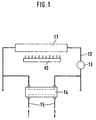
- FIG. 1 shows a simplified Representation of the common to all embodiments Basic structure
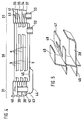
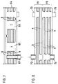
- Figures 2 to 4 each have a cross section the first, second and third embodiment
- Figure 5 enlarged a detail from Figure 4
- Figure 6 the Bottom view of a fourth embodiment
- the Figures 7 and 8 each have a cross section through the fifth and sixth embodiment.
- All of the embodiments have one from a heat source 10 heated primary heat exchanger 11 in a heating water network 12, the one via a circulation pump 13 and one Secondary heat exchanger and a hot water tank existing unit 14 leads, the heat from the heating water transfers to the water in a service water pipe 15.
- the hot water tank is in close thermal contact with the plate construction Secondary heat exchanger and can be used both for storage of domestic water, as well as heating water, or both be provided.
- a Secondary heat exchanger 18 through a stack of plates 19th formed, the 20 tight at their erected edges are interconnected and changing channels a for Limit heating water and channels b for process water.
- the Channels a and b are connected in parallel connected via passages 21, 22 which through appropriate shape of the plates 19 formed and against the intermediate, the other fluid leading Channels are sealed.
- a Connection piece 23 for one strand of the heating water network 12 attached, which leads into the passages 21. Removed from Connection piece 23 and not visible in the drawing is a second group of passages connecting the channels a and a corresponding connection piece for the another strand of the heating water network 12 is arranged.
- the incoming strand of the domestic water pipe 15 is in a hot water tank 25 performed on the Secondary heat exchanger 18 is placed and with this one Unit forms.
- a connecting piece 26 on the secondary heat exchanger 18th and a tube 27 provided through the passages 22 in the hot water tank 25 is guided.
- the tube 27 extends therein to a location 28 which removes is arranged by the group of passages 22 whose top immediately opens into the hot water tank 25. Removed from the connector 26 and not in the drawing a second group of channels b is visible connecting passages and a corresponding one Connection piece for the further strand of Service water line 15 arranged.
- the hot water tank 25 is in a large area close thermal contact with the plate 19 of the Secondary heat exchanger 18 which the upper heating water channel a limited.
- the flow in the hot water tank 25 is on this plate 19 inevitably led along and the exit of the hot water tank 25 opens out in the shortest possible way, i.e. directly into the group of service water channels b.
- the Storage volume is due to the already existing Heat exchanger function heated up, so that an additional There is no heat exchanger for the domestic hot water tank.
- FIG. 3 corresponds to that according to FIG. 2 except for the feature that the hot water tank 25th between two heating water channels a of the secondary heat exchanger is arranged so that there is an even more intense thermal contact between the heating water and the Hot water in the hot water tank 25 results.
- the hot water tank could also be exemplary embodiments be arranged on the heating water side.
- the Hot water tank even deeper in the plate stack of the Secondary heat exchanger, so that it is both from the heating water process water is also washed around in the secondary heat exchanger.
- a Secondary heat exchanger 30 a base body by a also made in panel construction Domestic hot water tank 31 is included.
- the Secondary heat exchanger 30 is on the underside Connections for the heating network 12 connected, of which one, 32, lies in the plane of the drawing and the other, not visible in the drawing, arranged away from it is.
- the internal structure of the secondary heat exchanger 30 is correct corresponds to that of Figure 2, so that not is received.
- the hot water tank 31 is with a Connection piece 33 for the incoming strand of Process water line 15 connected to an annular chamber 34 opens out, through which two further annular chambers 35, 36 are arranged.
- the annular chambers 34, 35, 36 are by plates 37, 38, 39, 40 limited, which is integral with the plates of the Secondary heat exchanger 30 are connected. This is a excellent thermal contact between the two Assemblies given.
- the annular chamber 34 is with the annular chamber 35 via an opening not visible in the drawing in the Plate 38 connected to the connecting piece 33 approximately diagonally opposite.
- the annular chamber 35 is a Opening 41 in the plate 39 connected to the annular chamber 36, which is arranged approximately coaxially to the connecting piece 33.
- the annular chamber 40 is attached to the plate 39 and pipe passed through the other plates 38, 37 42 connected to a chamber 43 which is between the lower Plate 37 and a hood 44 attached thereto is formed.
- the hood 44 extends in the area of Secondary heat exchanger 30 and engages there in the one Plate 37 arranged opening 45 through which the inflowing Service water enters the service water channels b.
- the alternative solution shown in Figure 6 for execution 4 has a secondary heat exchanger as the base body 50, which is enclosed by a heating water tank 51.
- the secondary heat exchanger 50 On the bottom is the secondary heat exchanger 50 with Connections 52, 53 for the hot water pipe 15 and one Provide connection 54 for the heating network 12.
- the inner one Structure of the secondary heat exchanger 50 and Domestic hot water tank 31 corresponds to the version Figure 4.
- the heating water tank 51 has a connection 55 for the second strand of the heating network 12, which in the lower Annulus 34 opens. This is via an opening 56 in the cover plate with the overlying ring chamber 35 connected, one of which is approximately coaxial with the terminal 55 arranged opening leads into the third annular chamber 36.
- connection 55 there is a pipe 42 in FIG. 4 corresponding channel 57 is provided, the third Annular chamber 36 to the underside of the heating water tank 51 leads.
- the channel 57 through a hood 58 with a Opening 59 in the bottom plate of the Secondary heat exchanger 50 connected to the input whose heating water channels forms.
- the special thing about the Execution according to Figure 6 is that between the Connection piece 50 and the underlying, the Annular chambers 35 and 36 connecting opening on the one hand and the leading from the annular chamber 34 into the annular chamber 35 Opening 56 on the other hand a partition 60 is provided, which penetrates all annular chambers and for example through appropriate embossing of the plates is formed.
- the Partition 60 forces one through in each annular chamber dashed line 61 indicated ring flow of the Heating water, which in the annular chambers 34 and 36 in Clockwise and in the annular chamber 35 against Runs clockwise. This makes it a particularly intense one Heat exchange between the heating water and the domestic water reached.
- FIG. 7 In the embodiment of Figure 7 are inside of a secondary heat exchanger 64 two storage spaces 65 and 66 integrated for process water, which at a connection piece 67 is supplied, the storage spaces 65, 66 in succession runs through and then in the parallel Service water channels b reaches the secondary heat exchanger. Out the process water flows through one in the drawing not visible, lying behind the connecting piece 67 Connection piece in the continuing strand of Service water line 15 from.
- the connections for the heating water and the internal connections of the parallel ones Heating water channels are in the drawing of simplicity omitted for the sake of it.
- the arrangement could also be so be that the storage spaces 65, 66 in the course of Heating water network and that as in Figure 4 individual Protruding plates with tongues into the storage spaces 65, 66.
- the embodiment of Figure 8 has one Secondary heat exchanger 70, on which a hot water tank 71st is attached, which is also carried out in panel construction is and both heating water channels a and Service water ducts b contains.
- the hot water channels b are in the hot water tank 71 in series and in Secondary heat exchanger 70 connected in parallel.
- the Heating water channels a are parallel in both assemblies 70, 71 switched.
- the channels a, b in the hot water tank 71 are internally with channels a, b in secondary heat exchanger 70 connected, so that in this case also special means and Measures for this are not required.
- the hot water tank 71 has a connection piece 72 for the incoming strand of the domestic water pipe 15 and one Connection piece 73 for the heating network 12.
- the Secondary heat exchanger 70 is with a connecting piece 74 for the heating network 12 and a connection 75 for the Continuing strand of the domestic water line 15 provided.
- the embodiment according to FIG. 8 is characterized by a particularly fast thermal coupling of the memory the secondary heat exchanger.
Landscapes
- Engineering & Computer Science (AREA)
- Physics & Mathematics (AREA)
- Thermal Sciences (AREA)
- Mechanical Engineering (AREA)
- General Engineering & Computer Science (AREA)
- Chemical & Material Sciences (AREA)
- Combustion & Propulsion (AREA)
- Water Supply & Treatment (AREA)
- Heat-Pump Type And Storage Water Heaters (AREA)
- Thermally Insulated Containers For Foods (AREA)
- Cookers (AREA)
- Resistance Heating (AREA)
- Steam Or Hot-Water Central Heating Systems (AREA)
Abstract
Description
Die Erfindung geht aus von einem Brauchwasserbereiter nach der Gattung des Hauptanspruchs. Brauchwasserbereiter dieser Gattung, wie sie z.B. in Heizgeräten von Zentralheizungsanlagen eingebaut sind, zeichnen sich durch einen erhöhten Brauchwasserkomfort aus, weil beim Zapfen von Brauchwasser sofort warmes Wasser zur Verfügung steht. Bei bekannten Brauchwasserbereitern der gattungsmäßigen Art ist ein Warmwasserspeicher als eine getrennte Baueinheit ausgebildet, die über Rohre mit dem Sekundärwärmetauscher verbunden ist. Diese Ausführung beansprucht verhältnismäßig viel Einbauraum, der bei Heizgeräten der obengenannten Art nur knapp bemessen ist. Wegen der Rohrverbindungen ist der thermische Kontakt zwischen Warmwasserspeicher und Sekundärwärmetauscher nur begrenzt und die Anordnung eines separaten Warmwasserspeichers ist auch verhältnismäßig kostenintensiv.The invention is based on a water heater the genus of the main claim. Water heater this Genus as e.g. in heaters from Central heating systems are built in increased convenience of hot water because when tapping Domestic hot water is immediately available. At known water heaters of the generic type a hot water tank as a separate unit trained over pipes with the secondary heat exchanger connected is. This version claims proportionately a lot of installation space that is required for heaters of the type mentioned above is scarce. Because of the pipe connections thermal contact between the hot water tank and Secondary heat exchanger only limited and the arrangement of one separate hot water tank is also proportionate expensive.
Die erfindungsgemäße Anordnung mit den Merkmalen des Hauptanspruchs ergibt eine kompakte und platzsparende Baueinheit, bei welcher der thermische Kontakt zwischen dem Speichervolumen und dem Sekundärwärmetauscher erheblich verbessert ist und die Verbindungs- und Wärmeübertragungselemente in die Wärmetauscherplatten funktionsintegrierbar sind. Dadurch ergibt sich auch eine wesentliche Kostenersparnis im Vergleich zu einem separaten Warmwasserspeicher, der aufwendig mit dem Sekundärwärmetauscher verbunden werden muß.The arrangement according to the invention with the features of The main claim results in a compact and space-saving Unit in which the thermal contact between the Storage volume and the secondary heat exchanger significantly is improved and the connection and Heat transfer elements in the heat exchanger plates are function-integrable. This also results in a significant cost savings compared to a separate one Hot water tank, which is expensive with the Secondary heat exchanger must be connected.
Durch die in den Unteransprüchen aufgeführten Merkmale sind vorteilhafte Ausgestaltungen und Weiterbildungen der Anordnung nach dem Hauptanspruch möglich.By the features listed in the subclaims advantageous refinements and developments of Arrangement possible according to the main claim.
Die Auskühlverluste des Warmwasserspeichers können verringert werden, wenn dieser im Zuge der Brauchwasserleitung liegt, weil die Temperatur von gespeichertem Brauchwasser geringer als die Temperatur von gespeichertem Heizwasser gehalten werden kann. Dem Bestreben nach möglichst kompakter Bauweise wird entsprochen, wenn auch der Warmwasserspeicher in Plattenbauweise ausgeführt ist. Dadurch ist auch eine besonders enge thermische Anbindung des Warmwasserspeichers an den Sekundärwärmetauscher möglich.The cooling losses of the hot water tank can be reduced if this in the course of Domestic water pipe is because the temperature of stored domestic water less than the temperature of stored heating water can be kept. The aspiration according to the most compact design possible, is met if the hot water tank is also made of panels is. This is also a particularly tight thermal Connection of the hot water tank to the Secondary heat exchanger possible.
Der Warmwasserspeicher kann platzsparend an den Sekundärwärmetauscher angesetzt sein. Bei einer bevorzugten Ausführung ist der Warmwasserspeicher den als Grundkörper der Baueinheit ausgebildeten Sekundärwärmetauscher umschließend ausgebildet. Dadurch ergeben sich große Kontaktflächen zwischen den beiden Baugruppen und der weitere Vorteil, daß die Abwärme des Sekundärwärmetauschers an die Umgebungsluft, bedingt durch das stehende Speichervolumen, geringer ist als bei einem einseitigen Anbau des Warmwasserspeichers an den Plattenstapel des Sekundärwärmetauschers. The hot water tank can be used to save space Secondary heat exchanger must be attached. In a preferred one The hot water tank is designed as a basic body the unit trained secondary heat exchanger comprehensively trained. This results in great ones Contact areas between the two modules and the further advantage that the waste heat from the secondary heat exchanger to the ambient air due to the standing Storage volume, is less than a one-sided Attachment of the hot water tank to the plate stack of the Secondary heat exchanger.
Ein besonders enger Kontakt zwischen Warmwasserspeicher und Sekundärwärmetauscher ergibt sich, wenn das Speichervolumen des Warmwasserspeichers in den Sekundärwärmetauscher integriert ist.A particularly close contact between the hot water tank and Secondary heat exchanger results when the storage volume of the hot water tank in the secondary heat exchanger is integrated.
Bei allen Kombinationsvarianten mit einem Heizwasserspeicher ist es vorteilhaft, wenn die Schnittstelle zwischen dem Heizwasserspeicher und dem Sekundärwärmetauscher mit einem Anschluß zum unmittelbaren, den Speicher umgehenden Zuführen des Heizwassers in den Sekundärwärmetauscher versehen ist.In all combination variants with a heating water tank it is advantageous if the interface between the Heating water tank and the secondary heat exchanger with one Connection for immediate feeding that bypasses the storage of the heating water is provided in the secondary heat exchanger.
Ein "Durchschießen" des Brauch- bzw. Heizwassers durch den Warmwasserspeicher wird vermieden, wenn der Warmwasserspeicher in einzelne, hintereinandergeschaltete Bereiche unterteilt ist, die vom Wasser nacheinander durchströmt werden.A "shooting" of the service or heating water through the Hot water storage tank is avoided if the Hot water storage tank in individual, connected in series Areas are divided by the water one by one be flowed through.
Sechs Ausführungsbeispiele der Erfindung sind in der Zeichnung dargestellt und in der nachfolgenden Beschreibung naher erläutert. Es zeigen Figur 1 eine vereinfachte Darstellung des allen Ausführungsbeispielen gemeinsamen Grundaufbaus, die Figuren 2 bis 4 je einen Querschnitt durch das erste, zweite und dritte Ausführungsbeispiel, Figur 5 vergrößert eine Einzelheit aus Figur 4, Figur 6 die Unteransicht eines vierten Ausführungsbeispiels und die Figuren 7 und 8 je einen Querschnitt durch das fünfte und sechste Ausführungsbeispiel.Six embodiments of the invention are in the Drawing shown and in the description below explained in more detail. 1 shows a simplified Representation of the common to all embodiments Basic structure, Figures 2 to 4 each have a cross section the first, second and third embodiment, Figure 5 enlarged a detail from Figure 4, Figure 6 the Bottom view of a fourth embodiment and the Figures 7 and 8 each have a cross section through the fifth and sixth embodiment.
Alle Ausführungsbeispiele haben einen von einer Wärmequelle
10 beheizten Primärwärmetauscher 11 in einem Heizwassernetz
12, das über eine Umwälzpumpe 13 und eine aus einem
Sekundärwärmetauscher und einem Warmwasserspeicher
bestehende Baueinheit 14 führt, die Wärme aus dem Heizwasser
auf das Wasser in einer Brauchwasserleitung 15 überträgt.
Der Warmwasserspeicher steht in engem thermischen Kontakt
mit dem in Plattenbauweise ausgeführten
Sekundärwärmetauscher und kann sowohl für die Speicherung
von Brauchwasser, als auch von Heizwasser, oder von beiden
vorgesehen sein.All of the embodiments have one from a
Beim Ausführungsbeispiel nach Figur 2 ist ein
Sekundärwärmetauscher 18 durch einen Stapel von Platten 19
gebildet, die an ihren aufgestellten Rändern 20 dicht
miteinander verbunden sind und wechselnde Kanäle a für
Heizwasser und Kanäle b für Brauchwasser begrenzen. Die
Kanäle a und b sind unter sich jeweils parallel geschaltet
über Durchgänge 21, 22 miteinander verbunden, die durch
entsprechende Formgebung der Platten 19 gebildet und gegen
die dazwischenliegenden, das jeweils andere Fluid führenden
Kanäle abgedichtet sind. Am Sekundärwärmetauscher 18 ist ein
Anschlußstutzen 23 für den einen Strang des Heizwassernetzes
12 befestigt, der in die Durchgänge 21 führt. Entfernt vom
Anschlußstutzen 23 und in der Zeichnung nicht sichtbar, ist
eine zweite Gruppe von die Kanäle a verbindenden Durchgängen
und ein damit korrespondierender Anschlußstutzen für den
anderen Strang des Heizwassernetzes 12 angeordnet.In the embodiment of Figure 2 is a
Der ankommende Strang der Brauchwasserleitung 15 ist in
einem Brauchwasserspeicher 25 geführt, der auf den
Sekundärwärmetauscher 18 aufgesetzt ist und mit diesem eine
Baueinheit bildet. Zum Anschließen der Brauchwasserleitung
15 sind ein Anschlußstutzen 26 am Sekundärwärmetauscher 18
und ein Rohr 27 vorgesehen, das durch die Durchgänge 22 in
den Brauchwasserspeicher 25 geführt ist. Das Rohr 27
erstreckt sich darin bis zu einer Stelle 28, die entfernt
von der Gruppe der Durchgänge 22 angeordnet ist, deren
oberster unmittelbar in den Brauchwasserspeicher 25 mündet.
Entfernt vom Anschlußstutzen 26 und in der Zeichnung nicht
sichtbar ist eine zweite Gruppe von die Kanäle b
verbindenden Durchgängen und ein damit korrespondierender
Anschlußstutzen für den weitergehenden Strang der
Brauchwasserleitung 15 angeordnet.The incoming strand of the
Der Brauchwasserspeicher 25 steht über eine große Fläche in
engem thermischen Kontakt mit der Platte 19 des
Sekundärwärmetauschers 18 die den oberen Heizwasserkanal a
begrenzt. Die Strömung im Brauchwasserspeicher 25 wird an
dieser Platte 19 zwangsläufig entlanggeführt und der Ausgang
des Brauchwasserspeichers 25 mündet auf kürzestem Wege, d.h.
unmittelbar in die Gruppe der Brauchwasserkanäle b ein. Das
Speichervolumen wird durch die ohnehin vorhandene
Wärmetauscherfunktion aufgeheizt, so daß ein zusätzlicher
Wärmetauscher für den Brauchwasserspeicher entfällt.The
Die Ausführung nach Figur 3 stimmt mit jener nach Figur 2
bis auf das Merkmal überein, daß der Brauchwasserspeicher 25
zwischen zwei Heizwasserkanälen a des Sekundärwärmetauschers
angeordnet ist, so daß sich ein noch intensiverer
thermischer Kontakt zwischen dem Heizwasser und dem
Brauchwasser im Brauchwasserspeicher 25 ergibt. Bei beiden
Ausführungsbeispielen könnte der Warmwasserspeicher auch
heizwasserseitig angeordnet sein.3 corresponds to that according to FIG. 2
except for the feature that the hot water tank 25th
between two heating water channels a of the secondary heat exchanger
is arranged so that there is an even more intense
thermal contact between the heating water and the
Hot water in the
Bei einer alternativen Ausführung sitzt der Warmwasserspeicher noch tiefer im Plattenstapel des Sekundärwärmetauschers, so daß er sowohl vom Heizwasser als auch vom Brauchwasser im Sekundärwärmetauscher umspült ist.In an alternative version, the Hot water tank even deeper in the plate stack of the Secondary heat exchanger, so that it is both from the heating water process water is also washed around in the secondary heat exchanger.
Beim Ausführungsbeispiel nach den Figuren 4 und 5 bildet ein
Sekundärwärmetauscher 30 einen Grundkörper, der von einem
ebenfalls in Plattenbauweise ausgeführten
Brauchwasserspeicher 31 umfaßt ist. Der
Sekundärwärmetauscher 30 ist an der Unterseite mit
Anschlußstutzen für das Heizungsnetz 12 verbunden, von denen
der eine, 32, in der Zeichnungsebene liegt und der andere,
in der Zeichnung nicht sichtbare, entfernt davon angeordnet
ist. Der innere Aufbau des Sekundärwärmetauschers 30 stimmt
mit jenem nach Figur 2 überein, so daß hierauf nicht
eingegangen wird. Der Brauchwasserspeicher 31 ist mit einem
Anschlußstutzen 33 für den ankommenden Strang der
Brauchwasserleitung 15 verbunden, der in eine Ringkammer 34
mündet, über welche noch zwei weitere Ringkammern 35, 36
angeordnet sind.In the embodiment according to Figures 4 and 5 forms a
Secondary heat exchanger 30 a base body by a
also made in panel construction
Domestic
Die Ringkammern 34, 35, 36 sind durch Platten 37, 38, 39, 40
begrenzt, die einstückig mit den Platten des
Sekundärwärmetauschers 30 verbunden sind. Dadurch ist ein
hervorragender thermischer Kontakt zwischen den beiden
Baugruppen gegeben. Die Ringkammer 34 ist mit der Ringkammer
35 über eine in der Zeichnung nicht sichtbare Öffnung in der
Platte 38 verbunden, die dem Anschlußstutzen 33 etwa
diagonal gegenüberliegt. Die Ringkammer 35 ist über eine
Öffnung 41 in der Platte 39 mit der Ringkammer 36 verbunden,
die etwa koaxial zum Anschlußstutzen 33 angeordnet ist.The
Die Ringkammer 40 ist über ein an der Platte 39 befestigtes
und durch die anderen Platten 38, 37 hindurchgeführtes Rohr
42 mit einer Kammer 43 verbunden, die zwischen der unteren
Platte 37 und einer daran befestigten Haube 44 gebildet ist.
Die Haube 44 erstreckt sich in den Bereich des
Sekundärwärmetauschers 30 und greift dort über eine in der
Platte 37 angeordnete Öffnung 45 über welche das zufließende
Brauchwasser in die Brauchwasserkanäle b gelangt. Durch die
versetzte Anordnung der Durchgänge von einer Kammer des
Brauchwasserspeichers 31 zur anderen ergibt sich eine
Reihenschaltung der Kammern, wobei ein "Durchschießen" des
Wassers durch den Speicher vermieden und das Brauchwasser in
jeder Kammer den Plattenstapel des Sekundärwärmetauschers 30
beidseitig umströmt. An der Unterseite des
Sekundärwärmetauschers 30 ist ein in der Zeichnung nicht
sichtbarer Anschlußstutzen für den weiterführenden Strang
der Brauchwasserleitung 15 entfernt von der Öffnung 45
angeordnet.The
Wie aus der Zeichnung ersichtlich, bildet nur jede zweite
Platte des Sekundärwärmetauschers 30 eine Trennwand zwischen
den Ringkammern 34, 35, 36, die daher die doppelte Höhe wie
die Kanäle im Sekundärwärmetauscher 30 haben. Die
dazwischenliegenden Platten 46 (Figur 5) weisen einen in die
entsprechende Ringkammer hineinragenden Rand 47 auf, der mit
örtlich herausgestellten Zungen 48 versehen ist. Durch diese
Anordnung wird die thermische Anbindung des Speichervolumens
an den Sekundärwärmetauscher 30 weiter erhöht.As can be seen from the drawing, only every second forms
Plate of the secondary heat exchanger 30 a partition between
the
Die in den Figuren 4 und 5 beschriebene Ausführung könnte
durch Vertauschen der Anschlüsse auch so eingesetzt werden,
daß Heizwasser gespeichert wird und das Brauchwasser nur die
Kanäle des Sekundärwärmetauschers füllt. In diesem Fall kann
es zweckmäßig sein, beispielsweise an der Haube 44 etwa
koaxial zur Öffnung 45 einen zweiten Anschlußstutzen für die
unmittelbare Zuführung von Heizwasser unter Umgehung des
Speichers vorzusehen.The embodiment described in Figures 4 and 5 could
can also be used by swapping the connections
that heating water is stored and the domestic water only that
Fills the channels of the secondary heat exchanger. In this case
it may be appropriate, for example on the
Die in Figur 6 dargestellte Alternativlösung zur Ausführung
nach Figur 4 hat als Grundkörper einen Sekundärwärmetauscher
50, der von einem Heizwasserspeicher 51 umschlossen ist. An
der Unterseite ist der Sekundärwärmetauscher 50 mit
Anschlüssen 52, 53 für die Brauchwasserleitung 15 und einem
Anschluß 54 für das Heizungsnetz 12 versehen. Der innere
Aufbau des Sekundärwärmetauschers 50 und des
Brauchwasserspeichers 31 entspricht der Ausführung nach
Figur 4. Der Heizwasserspeicher 51 hat einen Anschluß 55 für
den zweiten Strang des Heizungsnetzes 12, der in die untere
Ringkammer 34 mündet. Diese ist über eine Öffnung 56 in der
sie abdeckenden Platte mit der darüberliegenden Ringkammer
35 verbunden, von der eine etwa koaxial zum Anschluß 55
angeordnete Öffnung in die dritte Ringkammer 36 führt.The alternative solution shown in Figure 6 for execution
4 has a secondary heat exchanger as the
Neben dem Anschluß 55 ist ein dem Rohr 42 der Figur 4
entsprechender Kanal 57 vorgesehen, der aus der dritten
Ringkammer 36 zur Unterseite des Heizwasserspeichers 51
führt. Dort ist der Kanal 57 durch eine Haube 58 mit einer
Öffnung 59 in der untersten Platte des
Sekundärwärmetauschers 50 verbunden, die den Eingang zu
dessen Heizwasserkanälen bildet. Das besondere an der
Ausführung nach Figur 6 ist, daß zwischen dem
Anschlußstutzen 50 und der darunterliegenden, die
Ringkammern 35 und 36 verbindenden Öffnung einerseits und
der von der Ringkammer 34 in die Ringkammer 35 führenden
Öffnung 56 andererseits eine Trennwand 60 vorgesehen ist,
die alle Ringkammern durchsetzt und beispielsweise durch
entsprechende Prägungen der Platten gebildet ist. Die
Trennwand 60 erzwingt in jeder Ringkammer eine durch die
strichlinierte Linie 61 angedeutete Ringströmung des
Heizwassers, die in den Ringkammern 34 und 36 im
Uhrzeigersinn und in der Ringkammer 35 entgegen dem
Uhrzeigersinn verläuft. Dadurch ist ein besonders intensiver
Wärmeaustausch zwischen dem Heizwasser und dem Brauchwasser
erreicht.In addition to the
Beim Ausführungsbeispiel nach Figur 7 sind in das Innere
eines Sekundärwärmetauschers 64 zwei Speicherräume 65 und 66
für Brauchwasser integriert, das an einem Anschlußstutzen 67
zugeführt ist, die Speicherräume 65, 66 nacheinander
durchläuft und danach in die parallel geschalteten
Brauchwasserkanäle b des Sekundärwärmetauschers gelangt. Aus
diesem strömt das Brauchwasser durch einen in der Zeichnung
nicht sichtbaren, hinter dem Anschlußstutzen 67 liegenden
Anschlußstutzen in den weiterführenden Strang der
Brauchwasserleitung 15 ab. Die Anschlüsse für das Heizwasser
und die inneren Verbindungen der parallel geschalteten
Heizwasserkanäle sind in der Zeichnung der Einfachheit
halber weggelassen. Die Anordnung könnte auch so getroffen
sein, daß die Speicherräume 65, 66 im Zuge des
Heizwassernetzes liegen und daß wie bei Figur 4 einzelne
Platten mit Zungen in die Speicherräume 65, 66 hineinragen.In the embodiment of Figure 7 are inside
of a
Das Ausführungsbeispiel nach Figur 8 hat einen
Sekundärwärmetauscher 70, auf den ein Warmwasserspeicher 71
aufgesetzt ist, der ebenfalls in Plattenbauweise ausgeführt
ist und sowohl Heizwasserkanäle a als auch
Brauchwasserkanäle b enthält. Die Brauchwasserkanäle b sind
im Warmwasserspeicher 71 in Reihe und im
Sekundärwärmetauscher 70 parallel geschaltet. Die
Heizwasserkanäle a sind in beiden Baugruppen 70, 71 parallel
geschaltet. Die Kanäle a, b im Warmwasserspeicher 71 sind
intern mit den Kanälen a, b im Sekundärwärmetauscher 70
verbunden, so daß auch in diesem Fall besondere Mittel und
Maßnahmen hierfür nicht benötigt werden.The embodiment of Figure 8 has one
Der Warmwasserspeicher 71 hat einen Anschlußstutzen 72 für
den zulaufenden Strang der Brauchwasserleitung 15 und einen
Anschlußstutzen 73 für das Heizungsnetz 12. Der
Sekundärwärmetauscher 70 ist mit einem Anschlußstutzen 74
für das Heizungsnetz 12 und einen Anschluß 75 für den
weiterführenden Strang der Brauchwasserleitung 15 versehen.
Die Ausführung nach Figur 8 zeichnet sich durch eine
besonders schnelle thermische Ankopplung des Speichers an
den Sekundärwärmetauscher aus.The hot water tank 71 has a
Claims (8)
Applications Claiming Priority (2)
| Application Number | Priority Date | Filing Date | Title |
|---|---|---|---|
| DE19742075A DE19742075A1 (en) | 1997-09-24 | 1997-09-24 | Water heater |
| DE19742075 | 1997-09-24 |
Publications (4)
| Publication Number | Publication Date |
|---|---|
| EP0905453A2 true EP0905453A2 (en) | 1999-03-31 |
| EP0905453A3 EP0905453A3 (en) | 2001-04-11 |
| EP0905453B1 EP0905453B1 (en) | 2003-06-18 |
| EP0905453B2 EP0905453B2 (en) | 2006-03-01 |
Family
ID=7843430
Family Applications (1)
| Application Number | Title | Priority Date | Filing Date |
|---|---|---|---|
| EP98110530A Expired - Lifetime EP0905453B2 (en) | 1997-09-24 | 1998-06-09 | Domestic hot water heater |
Country Status (3)
| Country | Link |
|---|---|
| EP (1) | EP0905453B2 (en) |
| AT (1) | ATE243306T1 (en) |
| DE (2) | DE19742075A1 (en) |
Cited By (5)
| Publication number | Priority date | Publication date | Assignee | Title |
|---|---|---|---|---|
| WO2001048433A1 (en) * | 1999-12-23 | 2001-07-05 | Alfa Laval Corporate Ab | Plate heat exchanger |
| WO2001057452A1 (en) * | 2000-02-01 | 2001-08-09 | Alfa Laval Corporate Ab. | Heater and/or cooler |
| JP2003517558A (en) * | 1999-12-15 | 2003-05-27 | スウエプ インターナシヨナル アーベー | Water heater with plate heat exchanger and hot water storage container |
| WO2006059208A1 (en) * | 2004-12-01 | 2006-06-08 | Cosmogas S.R.L. | Heat exchanger for a combined boiler, and combined boiler using said heat exchanger |
| EP1703213A1 (en) * | 2005-02-07 | 2006-09-20 | Robert Bosch Gmbh | Sanitary water heater |
Families Citing this family (1)
| Publication number | Priority date | Publication date | Assignee | Title |
|---|---|---|---|---|
| EP1850082A1 (en) * | 2006-04-24 | 2007-10-31 | Sundsvall Energi AB | Heat exchanger |
Citations (5)
| Publication number | Priority date | Publication date | Assignee | Title |
|---|---|---|---|---|
| DE2214711A1 (en) * | 1972-03-25 | 1973-10-04 | Egon Laforce | HOT WATER HEATER |
| DE4027965A1 (en) * | 1989-09-14 | 1991-03-28 | Austria Email Eht Ag | Water heating system in building - includes storage tank with external heat-exchanger and circulating pump |
| DE4236967A1 (en) * | 1991-11-04 | 1993-05-06 | Joh. Vaillant Gmbh U. Co, 5630 Remscheid, De | Heating system with circulating pump - has hot-water storage tank in series with primary branch of heat-exchanger |
| GB2262593A (en) * | 1991-12-17 | 1993-06-23 | Inter Albion Ltd | An apparatus for and method of providing hot sanitary water |
| EP0778450A1 (en) * | 1995-12-08 | 1997-06-11 | Chaffoteaux Et Maury | Apparatus for producing domestic hot water |
-
1997
- 1997-09-24 DE DE19742075A patent/DE19742075A1/en not_active Ceased
-
1998
- 1998-06-09 EP EP98110530A patent/EP0905453B2/en not_active Expired - Lifetime
- 1998-06-09 AT AT98110530T patent/ATE243306T1/en active
- 1998-06-09 DE DE59808742T patent/DE59808742D1/en not_active Expired - Lifetime
Patent Citations (6)
| Publication number | Priority date | Publication date | Assignee | Title |
|---|---|---|---|---|
| DE2214711A1 (en) * | 1972-03-25 | 1973-10-04 | Egon Laforce | HOT WATER HEATER |
| DE4027965A1 (en) * | 1989-09-14 | 1991-03-28 | Austria Email Eht Ag | Water heating system in building - includes storage tank with external heat-exchanger and circulating pump |
| DE4236967A1 (en) * | 1991-11-04 | 1993-05-06 | Joh. Vaillant Gmbh U. Co, 5630 Remscheid, De | Heating system with circulating pump - has hot-water storage tank in series with primary branch of heat-exchanger |
| GB2262593A (en) * | 1991-12-17 | 1993-06-23 | Inter Albion Ltd | An apparatus for and method of providing hot sanitary water |
| EP0778450A1 (en) * | 1995-12-08 | 1997-06-11 | Chaffoteaux Et Maury | Apparatus for producing domestic hot water |
| DE69617175T2 (en) * | 1995-12-08 | 2002-07-25 | Chaffoteaux Et Maury Chatou | Devices for the production of hot domestic water |
Cited By (6)
| Publication number | Priority date | Publication date | Assignee | Title |
|---|---|---|---|---|
| JP2003517558A (en) * | 1999-12-15 | 2003-05-27 | スウエプ インターナシヨナル アーベー | Water heater with plate heat exchanger and hot water storage container |
| EP1238231B2 (en) † | 1999-12-15 | 2007-05-16 | SWEP International AB | Water heater comprising a plate heat exchanger and a storage container for heated water |
| WO2001048433A1 (en) * | 1999-12-23 | 2001-07-05 | Alfa Laval Corporate Ab | Plate heat exchanger |
| WO2001057452A1 (en) * | 2000-02-01 | 2001-08-09 | Alfa Laval Corporate Ab. | Heater and/or cooler |
| WO2006059208A1 (en) * | 2004-12-01 | 2006-06-08 | Cosmogas S.R.L. | Heat exchanger for a combined boiler, and combined boiler using said heat exchanger |
| EP1703213A1 (en) * | 2005-02-07 | 2006-09-20 | Robert Bosch Gmbh | Sanitary water heater |
Also Published As
| Publication number | Publication date |
|---|---|
| DE19742075A1 (en) | 1999-03-25 |
| EP0905453B2 (en) | 2006-03-01 |
| EP0905453A3 (en) | 2001-04-11 |
| ATE243306T1 (en) | 2003-07-15 |
| EP0905453B1 (en) | 2003-06-18 |
| DE59808742D1 (en) | 2003-07-24 |
Similar Documents
| Publication | Publication Date | Title |
|---|---|---|
| DE60010226T2 (en) | HOUSING-FREE HEAT EXCHANGER WITH TURBULEN INSERT | |
| EP0653043B1 (en) | Heat exchanger | |
| DE19519740B4 (en) | heat exchangers | |
| EP0911156A1 (en) | Tempering assembly in printing machines | |
| EP3371540B1 (en) | Heat exchanger module | |
| DE3630084C2 (en) | ||
| EP1637020B1 (en) | Cooling system for a switchgear cabinet | |
| EP0905453B1 (en) | Domestic hot water heater | |
| DE102020207966A1 (en) | Cooling arrangement for electronic components of a motor vehicle | |
| EP1760407A1 (en) | Manifold for heating and cooling system | |
| DE102006004756A1 (en) | Peltier heat-exchanger in modular design, has water channels incorporated into heat-exchanger plates | |
| EP1852663B1 (en) | Solar collector unit | |
| DE4308626C1 (en) | Multiple distributor for fluidic coaxial lines | |
| DE102006020502A1 (en) | Heat exchanger unit arrangement, has substrate plate forming cover of channel, where flowing fluid in guiding channel running parallel to substrate plate is guided by substrate plate | |
| DE3509674A1 (en) | CONDENSATE BOILER | |
| DE202005007941U1 (en) | Regulated two-zone buffer storage for use in e.g. solar heat plant, has container divided into lower and upper chambers by circular blank, where heat exchangers are arranged in lower chamber that is formed in low temperature zone | |
| DE102004020602A1 (en) | Plate heat exchanger for internal combustion engine, has plate gaps with another two plate gaps, which guide one of three heat exchange fluids, where fluids are exchanged with each other in adjoining gaps in respective same row sequence | |
| DE19628708B4 (en) | water heating system | |
| DE1451246B2 (en) | Multi-plate heat exchanger | |
| AT410713B (en) | WATER HEATING SYSTEM | |
| EP0823599B1 (en) | Gas-fired water heater | |
| DE3230351C2 (en) | Device for coke cooling | |
| AT408146B (en) | HEATING DEVICE | |
| DE3009215A1 (en) | Multi-cyclone dust extractor for flue gases - uses heat exchangers in common raw and clean gas chambers | |
| DE10311532A1 (en) | Heat spreader module |
Legal Events
| Date | Code | Title | Description |
|---|---|---|---|
| PUAI | Public reference made under article 153(3) epc to a published international application that has entered the european phase |
Free format text: ORIGINAL CODE: 0009012 |
|
| AK | Designated contracting states |
Kind code of ref document: A2 Designated state(s): AT DE FR GB IT |
|
| AX | Request for extension of the european patent |
Free format text: AL;LT;LV;MK;RO;SI |
|
| PUAL | Search report despatched |
Free format text: ORIGINAL CODE: 0009013 |
|
| AK | Designated contracting states |
Kind code of ref document: A3 Designated state(s): AT BE CH CY DE DK ES FI FR GB GR IE IT LI LU MC NL PT SE |
|
| AX | Request for extension of the european patent |
Free format text: AL;LT;LV;MK;RO;SI |
|
| 17P | Request for examination filed |
Effective date: 20011011 |
|
| AKX | Designation fees paid |
Free format text: AT DE FR GB IT |
|
| GRAH | Despatch of communication of intention to grant a patent |
Free format text: ORIGINAL CODE: EPIDOS IGRA |
|
| GRAH | Despatch of communication of intention to grant a patent |
Free format text: ORIGINAL CODE: EPIDOS IGRA |
|
| GRAA | (expected) grant |
Free format text: ORIGINAL CODE: 0009210 |
|
| AK | Designated contracting states |
Designated state(s): AT DE FR GB IT |
|
| REG | Reference to a national code |
Ref country code: GB Ref legal event code: FG4D Free format text: NOT ENGLISH |
|
| REF | Corresponds to: |
Ref document number: 59808742 Country of ref document: DE Date of ref document: 20030724 Kind code of ref document: P |
|
| GBT | Gb: translation of ep patent filed (gb section 77(6)(a)/1977) |
Effective date: 20031027 |
|
| ET | Fr: translation filed | ||
| PLBI | Opposition filed |
Free format text: ORIGINAL CODE: 0009260 |
|
| PLAX | Notice of opposition and request to file observation + time limit sent |
Free format text: ORIGINAL CODE: EPIDOSNOBS2 |
|
| 26 | Opposition filed |
Opponent name: VAILLANT GMBH Effective date: 20040315 |
|
| PLBB | Reply of patent proprietor to notice(s) of opposition received |
Free format text: ORIGINAL CODE: EPIDOSNOBS3 |
|
| PUAH | Patent maintained in amended form |
Free format text: ORIGINAL CODE: 0009272 |
|
| STAA | Information on the status of an ep patent application or granted ep patent |
Free format text: STATUS: PATENT MAINTAINED AS AMENDED |
|
| 27A | Patent maintained in amended form |
Effective date: 20060301 |
|
| AK | Designated contracting states |
Kind code of ref document: B2 Designated state(s): AT DE FR GB IT |
|
| GBTA | Gb: translation of amended ep patent filed (gb section 77(6)(b)/1977) |
Effective date: 20060510 |
|
| ET3 | Fr: translation filed ** decision concerning opposition | ||
| PGFP | Annual fee paid to national office [announced via postgrant information from national office to epo] |
Ref country code: AT Payment date: 20110620 Year of fee payment: 14 |
|
| REG | Reference to a national code |
Ref country code: AT Ref legal event code: MM01 Ref document number: 243306 Country of ref document: AT Kind code of ref document: T Effective date: 20120609 |
|
| PG25 | Lapsed in a contracting state [announced via postgrant information from national office to epo] |
Ref country code: AT Free format text: LAPSE BECAUSE OF NON-PAYMENT OF DUE FEES Effective date: 20120609 |
|
| PGFP | Annual fee paid to national office [announced via postgrant information from national office to epo] |
Ref country code: GB Payment date: 20130620 Year of fee payment: 16 |
|
| PGFP | Annual fee paid to national office [announced via postgrant information from national office to epo] |
Ref country code: FR Payment date: 20130703 Year of fee payment: 16 |
|
| PGFP | Annual fee paid to national office [announced via postgrant information from national office to epo] |
Ref country code: DE Payment date: 20130828 Year of fee payment: 16 |
|
| PGFP | Annual fee paid to national office [announced via postgrant information from national office to epo] |
Ref country code: IT Payment date: 20130622 Year of fee payment: 16 |
|
| REG | Reference to a national code |
Ref country code: DE Ref legal event code: R119 Ref document number: 59808742 Country of ref document: DE |
|
| GBPC | Gb: european patent ceased through non-payment of renewal fee |
Effective date: 20140609 |
|
| REG | Reference to a national code |
Ref country code: FR Ref legal event code: ST Effective date: 20150227 |
|
| REG | Reference to a national code |
Ref country code: DE Ref legal event code: R119 Ref document number: 59808742 Country of ref document: DE Effective date: 20150101 |
|
| PG25 | Lapsed in a contracting state [announced via postgrant information from national office to epo] |
Ref country code: IT Free format text: LAPSE BECAUSE OF NON-PAYMENT OF DUE FEES Effective date: 20140609 Ref country code: DE Free format text: LAPSE BECAUSE OF NON-PAYMENT OF DUE FEES Effective date: 20150101 |
|
| PG25 | Lapsed in a contracting state [announced via postgrant information from national office to epo] |
Ref country code: GB Free format text: LAPSE BECAUSE OF NON-PAYMENT OF DUE FEES Effective date: 20140609 Ref country code: FR Free format text: LAPSE BECAUSE OF NON-PAYMENT OF DUE FEES Effective date: 20140630 |