EP0905018B1 - Dekompressionsvorrichtung für Luftfahrzeug - Google Patents
Dekompressionsvorrichtung für Luftfahrzeug Download PDFInfo
- Publication number
- EP0905018B1 EP0905018B1 EP98203224A EP98203224A EP0905018B1 EP 0905018 B1 EP0905018 B1 EP 0905018B1 EP 98203224 A EP98203224 A EP 98203224A EP 98203224 A EP98203224 A EP 98203224A EP 0905018 B1 EP0905018 B1 EP 0905018B1
- Authority
- EP
- European Patent Office
- Prior art keywords
- baffle
- grille
- assembly
- holes
- aircraft
- Prior art date
- Legal status (The legal status is an assumption and is not a legal conclusion. Google has not performed a legal analysis and makes no representation as to the accuracy of the status listed.)
- Expired - Lifetime
Links
- 230000006837 decompression Effects 0.000 title claims description 32
- 229920006266 Vinyl film Polymers 0.000 claims description 2
- XAGFODPZIPBFFR-UHFFFAOYSA-N aluminium Chemical compound [Al] XAGFODPZIPBFFR-UHFFFAOYSA-N 0.000 claims description 2
- 229910052782 aluminium Inorganic materials 0.000 claims description 2
- 239000011888 foil Substances 0.000 claims description 2
- 230000014759 maintenance of location Effects 0.000 description 9
- 230000000712 assembly Effects 0.000 description 2
- 238000000429 assembly Methods 0.000 description 2
- 238000004519 manufacturing process Methods 0.000 description 2
- 239000000853 adhesive Substances 0.000 description 1
- 230000001070 adhesive effect Effects 0.000 description 1
- 230000033228 biological regulation Effects 0.000 description 1
- 230000000903 blocking effect Effects 0.000 description 1
- 238000004140 cleaning Methods 0.000 description 1
- 230000001143 conditioned effect Effects 0.000 description 1
- 230000009977 dual effect Effects 0.000 description 1
- 230000007613 environmental effect Effects 0.000 description 1
- 238000009434 installation Methods 0.000 description 1
- 238000012423 maintenance Methods 0.000 description 1
- 238000013022 venting Methods 0.000 description 1
Images


Classifications
-
- B—PERFORMING OPERATIONS; TRANSPORTING
- B64—AIRCRAFT; AVIATION; COSMONAUTICS
- B64C—AEROPLANES; HELICOPTERS
- B64C1/00—Fuselages; Constructional features common to fuselages, wings, stabilising surfaces or the like
- B64C1/18—Floors
-
- B—PERFORMING OPERATIONS; TRANSPORTING
- B64—AIRCRAFT; AVIATION; COSMONAUTICS
- B64C—AEROPLANES; HELICOPTERS
- B64C1/00—Fuselages; Constructional features common to fuselages, wings, stabilising surfaces or the like
- B64C2001/009—Fuselages; Constructional features common to fuselages, wings, stabilising surfaces or the like comprising decompression panels or valves for pressure equalisation in fuselages or floors
Definitions
- This invention relates to vent systems used for controlling return airflow and rapid decompression airflow within the fuselage of commercial aircraft, particularly those commercial aircraft known as "wide bodies.”
- a large number of air grilles are provided in an aircraft to serve a dual purpose, i.e., delivery of fresh air, and, in an emergency, to allow for the rapid movement of very large quantities of air during decompression.
- Such air grilles also are desired to reduce noise in the aircraft by blocking airflow noise from coming through the grilles during normal operations. See, for example, the U.S. Patent 5,137,231 by Boss, that is assigned to the assignee of this invention.
- the original design requirements for this vent design include the need for a large effective opening (approximately 600cm 2 (100 in 2 )) for lower lobe decompression.
- a small effective opening (approximately 60cm 2 (10 in 2 )) must be provided for main cabin decompression.
- the vent must provide this effective opening within fractions of a second (approximately 40 msec) at a very low pressure differential (approximately 15 psig) upon the onset of a rapid decompression.
- the small effective opening is also required for the normal air return flow from main cabin to lower lobe. The small opening creates a pressure drop that yields a direct air return flow through the vent assembly.
- This invention pertains to a vent assembly for use in aircraft and solves the problem of having to use heavy, mechanically complex and expensive vents for controlling return airflow and rapid decompression airflow within the fuselage of commercial aircraft.
- Prior attempts in solving the regulation of return airflow and rapid decompression airflow have resulted in the creation of heavy and expensive assemblies made of many diverse parts.
- Previous designs have relied on complex mechanical features, such as pivoting louvers hinged door/gates, and multiple baffles, for controlling the airflow.
- These prior vents are very costly because of the high recurring cost associated with assembling them. These assemblies have also required extensive adjustments in order to achieve the desired airflows.
- baffles in this prior art assembly have to be installed either during manufacture or later on in the aircraft, in both cases requiring cumbersome manual labour.
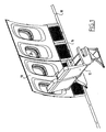
- FIGURE 1 shows an aircraft sidewall 10 and four of the decompression vents 16 of this invention as they are installed in an aircraft passenger cabin.
- Seats 12, windows 14, decompression vents 16, and a floor support angle 18 are attached to the floor beams.
- the two forward seats have been removed to aid visibility behind the forward seats,
- FIGURE 2 shows normal, non-decompression, low velocity airflow 20 moving from the passenger cabin 22 enroute to the cargo compartment 24 below.
- the decompression vents serve to circulate passenger return airflow, utilizing only several of the lower louvers of molded grille 28.
- the upper louvers are blocked by the thin baffle in this "normal" mode of operation.
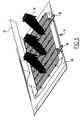
- FIGURE 3 is an isometric drawing showing the back side of the decompression vent 16.
- FIGURE 4 is an isometric drawing showing the backside of a decompression vent 16 during rapid decompression as shown by the airflow direction indicators 26.
- the thin baffle 32 is no longer attached to the molded grille 28 except at the upper row of bosses 40 and retention fasteners.
- FIGURE 5 shows details of the molded grille 28 which is held in place by multiple latches 30 while the thin baffle 32 is shown to be partly disconnected from the molded grille 28 to allow unrestricted airflow during rapid decompression from the passenger cabin to the cargo compartment.
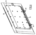
- FIGURE 6 shows a molded grille 28 with retention and release means for 34 and means 35 for permanently attaching the thin baffle 32 to the molded grille 28.
- FIGURE 7 shows the baffle 32 held by retention and release means 34 on the back of the grille 28.
- Retention means 34 such as standard screws engaged into the molded grille 28.
- the preferred embodiment includes a grille having a rectangular planar baffle which includes slits and holes manufactured using a blanking dic.
- the holes are 0.51 cm (.20 inches) in diameter and have four slits that are 0.89 cm (.35 inches) in length as measured from the center of the hole.
- the baffle 32 is a laminate comprised of vinyl films about 0.03 mm (.001 inches) thick and layers of aluminum foil 0.08 mm (.003 inches) thick and adhesive.
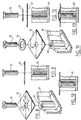
- FIGURES 8, 9, and 10 show the retention and release means 34, which, in this embodiment, retains the thin baffle 32 attached to the boss 40 of the molded grille 28 by a screw 42.
- a cut 44 and a circular hole 33 have been made in the thin baffle 32 to ease the assembly of the parts.
- FIGURES 11, 12 and 13 show the same parts as FIGURES 8, 9, and 10 except that
- FIGURES 11, 12 and 13 do not have cuts extending through its circular hole and a washer is used to secure the fastener to prevent any movement during the service life of the aircraft. It should be apparent that the intent is to allow all but one row at the top of the thin baffle to be disconnected to allow full venting under decompression loads.
- the fastener installation of FIGURE 10 is designed to allow the pressure loading of a rapid decompression to pull out and disconnect the thin baffle from the fasteners of FIGURE 10.
Landscapes
- Engineering & Computer Science (AREA)
- Mechanical Engineering (AREA)
- Aviation & Aerospace Engineering (AREA)
- Air-Conditioning For Vehicles (AREA)
- Air-Flow Control Members (AREA)
Claims (7)
- Baugruppe einer Frontplatte eines/r Rückluftentlüfters /Dekompressionsvorrichtung für ein Flugzeug umfassend ein modelliertes Gitter (28) zum Abdecken eines Rückluftentlüfters in einem Flugzeug und eine flexible Umlenkung (32), die ablösbar an der Ausströmseite des Gitters angebracht ist und davon einen Abschnitt überdeckt,
wobei die Umlenkung (32) eine Mehrzahl von Löchern darin und vier sich von jedem Loch auswärts erstreckende Schlitze (38) besitzt;
wobei das Gitter (28) eine Mehrzahl von an der Ausströmseite davon angebrachten Befestigungen mit Kopf besitzt, und
wobei die Position und Größe der Löcher, Schlitze (38) und Köpfe von den Befestigungen derart ausgestaltet sind, dass die Köpfe der Befestigungen durch die Löcher in der Umlenkung (32) während eines normalen Flugbetriebes hervorstehen, und die Umlenkung (32) sich zumindest teilweise im Fall einer raschen Dekompression von dem Gitter (28) ablöst. - Baugruppe nach Anspruch 1, wobei die Befestigung mit Kopf eine Schraube (42) ist.
- Baugruppe nach Anspruch 1 oder 2, wobei die Umlenkung (32) ein Verbundwerkstoff ist, der einen Vinylfilm und eine Aluminiumfolie umfasst.
- Baugruppe nach Anspruch 1, 2 oder 3, wobei die Umlenkung (32) entlang einer Oberkante fest an dem Gitter (28) angebracht ist.
- Baugruppe nach einem der Ansprüche 1 bis 4, welche zusätzlich zumindest eine nah an einer Oberkante der Umlenkung (32) angeordnete Befestigung mit Kopf umfasst, um an dieser Position die Umlenkung (32) fest an dem Gitter (28) anzubringen.
- Baugruppe nach einem der Ansprüche 1 bis 4, wobei die Umlenkung (32) eine Mehrzahl von horizontalen Reihen von derart angeordneten Löchern, dass sie über eine entsprechende Anzahl von Reihen von Befestigungen mit Kopf auf dem Gitter (28) passen, und eine Reihe von Löchern und Befestigungen entlang einer Oberkante des Gitters (28) besitzt, die derart angeordnet sind, dass die Umlenkung (32) entlang dieser Reihe an dem Gitter (28) fest angebracht ist.
- Baugruppe nach Anspruch 6, wobei die Umlenkung (32) entlang der Reihe mit Unterlegscheiben (53) und zum Gitter (28) hin befestigten Schrauben (52) an dem Gitter (28) fest angebracht ist.
Applications Claiming Priority (4)
| Application Number | Priority Date | Filing Date | Title |
|---|---|---|---|
| US6010997P | 1997-09-26 | 1997-09-26 | |
| US60109P | 1997-09-26 | ||
| US09/160,629 US6129312A (en) | 1997-09-26 | 1998-09-24 | Aircraft decompression vent assembly |
| US160629 | 1998-09-24 |
Publications (3)
| Publication Number | Publication Date |
|---|---|
| EP0905018A2 EP0905018A2 (de) | 1999-03-31 |
| EP0905018A3 EP0905018A3 (de) | 2000-12-06 |
| EP0905018B1 true EP0905018B1 (de) | 2003-04-16 |
Family
ID=26739569
Family Applications (1)
| Application Number | Title | Priority Date | Filing Date |
|---|---|---|---|
| EP98203224A Expired - Lifetime EP0905018B1 (de) | 1997-09-26 | 1998-09-28 | Dekompressionsvorrichtung für Luftfahrzeug |
Country Status (3)
| Country | Link |
|---|---|
| US (1) | US6129312A (de) |
| EP (1) | EP0905018B1 (de) |
| DE (1) | DE69813431T2 (de) |
Cited By (1)
| Publication number | Priority date | Publication date | Assignee | Title |
|---|---|---|---|---|
| US9440744B2 (en) | 2013-10-17 | 2016-09-13 | The Boeing Company | Decompression panel assembly and method of equalizing air pressure differential |
Families Citing this family (46)
| Publication number | Priority date | Publication date | Assignee | Title |
|---|---|---|---|---|
| DE19910779C2 (de) * | 1999-03-11 | 2002-01-24 | Airbus Gmbh | In einer Flugzeugkabine angeordnetes Staufach für Handgepäck |
| USD512365S1 (en) | 2002-06-25 | 2005-12-06 | The Boeing Company | Aircraft window |
| US6736352B2 (en) | 2002-06-25 | 2004-05-18 | The Boeing Company | Aircraft windows and associated methods for installation |
| DE102004009017B3 (de) * | 2004-02-25 | 2005-08-04 | Aircabin Gmbh | Dekompressionsvorrichtung für einen abrupten Druckausgleich zwischen zwei getrennten Bereichen, insbesondere zwischen zwei druckbeaufschlagten Bereichen eines Flugzeugs |
| US7210655B2 (en) * | 2004-12-03 | 2007-05-01 | The Boeing Company | Reconfigurable interior sidewall |
| DE102005061189B4 (de) * | 2005-12-21 | 2015-01-08 | Airbus Operations Gmbh | Flugzeugrumpf mit Ober- und Unterdeck |
| DE102007046479B4 (de) * | 2006-12-13 | 2015-08-27 | Airbus Operations Gmbh | Brandschutzvorrichtung für ein Luft- oder Raumfahrzeug |
| DE102007011627A1 (de) * | 2007-01-23 | 2008-07-31 | Airbus Deutschland Gmbh | Innenverkleidung für ein Luftfahrzeug |
| USD592584S1 (en) * | 2007-04-18 | 2009-05-19 | Airbus Deutschland Gmbh | Side lining panel for an aircraft cabin |
| US7654487B2 (en) * | 2007-05-25 | 2010-02-02 | The Boeing Company | Vent baffle |
| US8696418B1 (en) * | 2007-07-03 | 2014-04-15 | American Airlines, Inc. | System and method for securing a panel such as an aircraft air grille |
| USD589872S1 (en) * | 2007-09-20 | 2009-04-07 | Airbus Sas | Aircraft window |
| USD654008S1 (en) | 2007-11-19 | 2012-02-14 | British Airways P.L.C. | Window frame |
| DE102007061433B4 (de) * | 2007-12-20 | 2012-10-25 | Airbus Operations Gmbh | Verbesserte Dekompressionseinrichtung mit einem einstellbaren Auslösedruck |
| DE102009006395B4 (de) * | 2009-01-28 | 2014-07-10 | Airbus Operations Gmbh | Dekompressionsvorichtung für ein Flugzeug |
| DE102009012015A1 (de) * | 2009-03-06 | 2010-09-09 | Airbus Deutschland Gmbh | Dekompressionsanordnung für ein Luftfahrzeug |
| DE102009038644B4 (de) | 2009-08-24 | 2015-01-08 | Airbus Operations Gmbh | Dekompressionselementbefestigungssystem für ein Flugzeug |
| US8651924B1 (en) * | 2010-05-06 | 2014-02-18 | The Boeing Company | Interlocking vent assembly for equalizing pressure in a compartment |
| USD719895S1 (en) * | 2010-05-13 | 2014-12-23 | Embraer S.A. | Aircraft interior sidewall |
| DE102010045197B4 (de) * | 2010-09-13 | 2013-10-24 | Airbus Operations Gmbh | Dekompressionsvorrichtung und Dekompressionssystem |
| US20120074258A1 (en) * | 2010-09-23 | 2012-03-29 | Be Intellectual Property, Inc. | Integrated aircraft interior |
| DE102011011976B4 (de) * | 2011-02-22 | 2013-11-14 | Airbus Operations Gmbh | Dekompressionsanordnung für ein Luftfahrzeug |
| US9518757B2 (en) * | 2012-12-18 | 2016-12-13 | David James Boyce | Air return grille assembly |
| US9796245B2 (en) | 2013-09-24 | 2017-10-24 | The Boeing Company | Grille for vehicle wall opening |
| US10071795B2 (en) | 2013-10-25 | 2018-09-11 | The Boeing Company | Clamp device for use with a decompression panel in an aircraft assembly |
| US9233747B2 (en) | 2013-10-25 | 2016-01-12 | The Boeing Company | Decompression panel for use in an aircraft assembly |
| USD726093S1 (en) * | 2013-10-25 | 2015-04-07 | The Boeing Company | Decompression panel |
| US9566759B2 (en) * | 2013-10-25 | 2017-02-14 | The Boeing Company | Decompression panel for use in an aircraft assembly |
| US9499251B2 (en) * | 2013-10-25 | 2016-11-22 | The Boeing Company | Decompression panel for use in an aircraft |
| US10330334B2 (en) | 2014-01-28 | 2019-06-25 | The Boeing Company | Pressure equalization vent for use in an aircraft assembly |
| US9592902B2 (en) * | 2014-02-17 | 2017-03-14 | The Boeing Company | Hatch assembly for use in a vehicle and method of assembling the same |
| USD817851S1 (en) | 2014-03-28 | 2018-05-15 | The Boeing Company | Decompression panel |
| US10220931B2 (en) * | 2015-11-09 | 2019-03-05 | The Boeing Company | Sidewall panel assembly and return air bridge for use in an aircraft assembly |
| US10494079B2 (en) | 2016-03-30 | 2019-12-03 | The Boeing Company | Decompression panel assembly and methods of manufacturing the same |
| US10399660B2 (en) * | 2016-06-06 | 2019-09-03 | The Boening Company | Decompression panel assembly and methods of assembling the same |
| US10279887B2 (en) | 2016-06-06 | 2019-05-07 | The Boeing Company | Decompression panel assembly and methods of assembling the same |
| USD861537S1 (en) * | 2017-03-02 | 2019-10-01 | Newtl | Bus |
| USD908054S1 (en) * | 2018-12-19 | 2021-01-19 | The Boeing Company | Decompression panel assembly |
| USD1012815S1 (en) * | 2019-06-12 | 2024-01-30 | The Boeing Company | Air grille panel |
| US11548613B2 (en) * | 2019-06-27 | 2023-01-10 | The Boeing Company | Air grille panel assembly, system, and method of installing the same in a vehicle |
| US10992120B2 (en) | 2019-07-01 | 2021-04-27 | The Boeing Company | Sidewall closeout area assembly, system, and method for routing conductive elements in an aircraft |
| US11362494B2 (en) | 2019-07-01 | 2022-06-14 | The Boeing Company | Assembly, system, and methods for installing conductive elements in an aircraft |
| JP7840644B2 (ja) * | 2020-07-23 | 2026-04-06 | ザ・ボーイング・カンパニー | 航空機で使用するための環境制御システム |
| GB2599962B (en) | 2020-10-19 | 2023-09-13 | Amsafe Bridport Ltd | An aircraft compartmental barrier |
| US11780553B2 (en) * | 2021-03-23 | 2023-10-10 | The Boeing Company | Latch assembly and aircraft having same |
| US20250002149A1 (en) * | 2023-06-28 | 2025-01-02 | The Boeing Company | Venting systems and methods for an internal cabin of an aircraft |
Family Cites Families (14)
| Publication number | Priority date | Publication date | Assignee | Title |
|---|---|---|---|---|
| US32554A (en) * | 1861-06-18 | Seedietg-hariiow | ||
| US3571977A (en) * | 1969-06-27 | 1971-03-23 | Boeing Co | Access and pressure release door latch mechanism |
| FR2123097B1 (de) * | 1970-12-23 | 1975-01-10 | Seita | |
| USRE32554E (en) | 1975-12-17 | 1987-12-08 | Mcdonnell Douglas Corporation | Vent structure |
| US4390152A (en) * | 1976-05-13 | 1983-06-28 | Lockheed Corporation | Aircraft decompression vent assembly |
| US4432514A (en) * | 1976-09-23 | 1984-02-21 | The Boeing Company | Decompression equalization relief valve |
| US4498261A (en) * | 1981-12-07 | 1985-02-12 | Continental Disc Corporation | Low pressure venting panel |
| DE3715328C1 (de) * | 1987-05-08 | 1988-08-18 | Messerschmitt Boelkow Blohm | Dekompressionspanel |
| DE3922025C1 (de) * | 1989-07-05 | 1990-08-09 | Messerschmitt-Boelkow-Blohm Gmbh, 8012 Ottobrunn, De | |
| US5118053A (en) * | 1989-09-27 | 1992-06-02 | The Boeing Company | Pressure equalization systems |
| US5069401A (en) * | 1989-11-15 | 1991-12-03 | The Boeing Company | Compartment partition and pressure relief door therefor |
| DE4002447C1 (en) * | 1990-01-27 | 1991-03-14 | Deutsche Airbus Gmbh, 2103 Hamburg, De | Decompression panel esp. for aircraft - consists of plate which is releasably held in de-compression opening and consists of two inter-strapped plate parts |
| US5137231A (en) * | 1991-04-29 | 1992-08-11 | The Boeing Company | Decompression venting grille for aircraft |
| US6029933A (en) * | 1997-08-01 | 2000-02-29 | The Boeing Company | Fire resistant pressure relief panel assembly |
-
1998
- 1998-09-24 US US09/160,629 patent/US6129312A/en not_active Expired - Lifetime
- 1998-09-28 DE DE69813431T patent/DE69813431T2/de not_active Expired - Lifetime
- 1998-09-28 EP EP98203224A patent/EP0905018B1/de not_active Expired - Lifetime
Cited By (1)
| Publication number | Priority date | Publication date | Assignee | Title |
|---|---|---|---|---|
| US9440744B2 (en) | 2013-10-17 | 2016-09-13 | The Boeing Company | Decompression panel assembly and method of equalizing air pressure differential |
Also Published As
| Publication number | Publication date |
|---|---|
| US6129312A (en) | 2000-10-10 |
| DE69813431D1 (de) | 2003-05-22 |
| DE69813431T2 (de) | 2003-10-30 |
| EP0905018A3 (de) | 2000-12-06 |
| EP0905018A2 (de) | 1999-03-31 |
Similar Documents
| Publication | Publication Date | Title |
|---|---|---|
| EP0905018B1 (de) | Dekompressionsvorrichtung für Luftfahrzeug | |
| US6264141B1 (en) | Aircraft decompression protection panel | |
| US11142321B2 (en) | Aircraft door and privacy panel assemblies | |
| US5137231A (en) | Decompression venting grille for aircraft | |
| US5871178A (en) | Decompression panel for aircraft partition | |
| USRE32554E (en) | Vent structure | |
| US7654487B2 (en) | Vent baffle | |
| US5253484A (en) | High reliability avionic cooling system | |
| EP1186531B1 (de) | Dekompressionsplatte für ein Luftfahrzeug | |
| US11279461B2 (en) | Flight deck barrier door, aircraft comprising flight deck barrier door, and method of using flight deck barrier door | |
| US11999490B2 (en) | Air curtain systems and methods for vehicle cabins | |
| US6010286A (en) | Apparatus for rigidly retaining cargo | |
| US4390152A (en) | Aircraft decompression vent assembly | |
| US4552325A (en) | Emergency smoke disposal system for pressurized aircraft | |
| US20090159748A1 (en) | Decompression Device With Adjustable Release Pressure | |
| US20120234973A1 (en) | Decompression Device and Decompression System | |
| US10494077B2 (en) | Decompression assembly with two decompression openings | |
| US5915652A (en) | Method and apparatus for restraining a cargo barrier net beam assembly | |
| EP3170739B1 (de) | Dekompressionsanordnung mit zwei dekompressionsöffnungen | |
| US11548613B2 (en) | Air grille panel assembly, system, and method of installing the same in a vehicle | |
| EP3170738B1 (de) | Dekomprimierungsanordnung mit einem luftkanal | |
| CN101014498B (zh) | 用于航空器的安全内门 | |
| CA3120220A1 (en) | Air deflector and system including the air deflector | |
| HK40057626B (en) | Air deflector and system including the air deflector |
Legal Events
| Date | Code | Title | Description |
|---|---|---|---|
| PUAI | Public reference made under article 153(3) epc to a published international application that has entered the european phase |
Free format text: ORIGINAL CODE: 0009012 |
|
| AK | Designated contracting states |
Kind code of ref document: A2 Designated state(s): DE FR GB |
|
| AX | Request for extension of the european patent |
Free format text: AL;LT;LV;MK;RO;SI |
|
| PUAL | Search report despatched |
Free format text: ORIGINAL CODE: 0009013 |
|
| AK | Designated contracting states |
Kind code of ref document: A3 Designated state(s): AT BE CH CY DE DK ES FI FR GB GR IE IT LI LU MC NL PT SE |
|
| AX | Request for extension of the european patent |
Free format text: AL;LT;LV;MK;RO;SI |
|
| 17P | Request for examination filed |
Effective date: 20010418 |
|
| AKX | Designation fees paid |
Free format text: DE FR GB |
|
| 17Q | First examination report despatched |
Effective date: 20011122 |
|
| GRAH | Despatch of communication of intention to grant a patent |
Free format text: ORIGINAL CODE: EPIDOS IGRA |
|
| GRAH | Despatch of communication of intention to grant a patent |
Free format text: ORIGINAL CODE: EPIDOS IGRA |
|
| GRAA | (expected) grant |
Free format text: ORIGINAL CODE: 0009210 |
|
| AK | Designated contracting states |
Designated state(s): DE FR GB |
|
| REG | Reference to a national code |
Ref country code: GB Ref legal event code: FG4D |
|
| REF | Corresponds to: |
Ref document number: 69813431 Country of ref document: DE Date of ref document: 20030522 Kind code of ref document: P |
|
| ET | Fr: translation filed | ||
| PLBE | No opposition filed within time limit |
Free format text: ORIGINAL CODE: 0009261 |
|
| STAA | Information on the status of an ep patent application or granted ep patent |
Free format text: STATUS: NO OPPOSITION FILED WITHIN TIME LIMIT |
|
| 26N | No opposition filed |
Effective date: 20040119 |
|
| REG | Reference to a national code |
Ref country code: FR Ref legal event code: PLFP Year of fee payment: 19 |
|
| REG | Reference to a national code |
Ref country code: FR Ref legal event code: PLFP Year of fee payment: 20 |
|
| PGFP | Annual fee paid to national office [announced via postgrant information from national office to epo] |
Ref country code: GB Payment date: 20170927 Year of fee payment: 20 Ref country code: FR Payment date: 20170925 Year of fee payment: 20 |
|
| PGFP | Annual fee paid to national office [announced via postgrant information from national office to epo] |
Ref country code: DE Payment date: 20170927 Year of fee payment: 20 |
|
| REG | Reference to a national code |
Ref country code: DE Ref legal event code: R071 Ref document number: 69813431 Country of ref document: DE |
|
| REG | Reference to a national code |
Ref country code: GB Ref legal event code: PE20 Expiry date: 20180927 |
|
| PG25 | Lapsed in a contracting state [announced via postgrant information from national office to epo] |
Ref country code: GB Free format text: LAPSE BECAUSE OF EXPIRATION OF PROTECTION Effective date: 20180927 |