EP0904989B1 - Method and device for activating of passenger safety systems in vehicles - Google Patents
Method and device for activating of passenger safety systems in vehicles Download PDFInfo
- Publication number
- EP0904989B1 EP0904989B1 EP98115900A EP98115900A EP0904989B1 EP 0904989 B1 EP0904989 B1 EP 0904989B1 EP 98115900 A EP98115900 A EP 98115900A EP 98115900 A EP98115900 A EP 98115900A EP 0904989 B1 EP0904989 B1 EP 0904989B1
- Authority
- EP
- European Patent Office
- Prior art keywords
- protection systems
- occupant protection
- vehicle occupant
- activating
- sensor
- Prior art date
- Legal status (The legal status is an assumption and is not a legal conclusion. Google has not performed a legal analysis and makes no representation as to the accuracy of the status listed.)
- Expired - Lifetime
Links
- 238000000034 method Methods 0.000 title claims description 28
- 230000003213 activating effect Effects 0.000 title claims description 17
- 230000004913 activation Effects 0.000 claims description 8
- 238000011156 evaluation Methods 0.000 claims description 8
- 230000010355 oscillation Effects 0.000 claims description 4
- 230000005236 sound signal Effects 0.000 claims description 4
- 230000001143 conditioned effect Effects 0.000 claims description 2
- 230000005855 radiation Effects 0.000 claims description 2
- 230000006870 function Effects 0.000 claims 3
- 230000001133 acceleration Effects 0.000 description 10
- 230000000875 corresponding effect Effects 0.000 description 5
- 230000001419 dependent effect Effects 0.000 description 5
- 230000001960 triggered effect Effects 0.000 description 4
- 230000002596 correlated effect Effects 0.000 description 3
- 238000005259 measurement Methods 0.000 description 3
- 238000013459 approach Methods 0.000 description 2
- 238000013461 design Methods 0.000 description 2
- 238000012544 monitoring process Methods 0.000 description 2
- 230000005540 biological transmission Effects 0.000 description 1
- 230000001939 inductive effect Effects 0.000 description 1
- 230000000977 initiatory effect Effects 0.000 description 1
- 230000007257 malfunction Effects 0.000 description 1
- 230000000737 periodic effect Effects 0.000 description 1
- 239000007787 solid Substances 0.000 description 1
- 238000001228 spectrum Methods 0.000 description 1
- 238000002604 ultrasonography Methods 0.000 description 1
Images
Classifications
-
- B—PERFORMING OPERATIONS; TRANSPORTING
- B60—VEHICLES IN GENERAL
- B60R—VEHICLES, VEHICLE FITTINGS, OR VEHICLE PARTS, NOT OTHERWISE PROVIDED FOR
- B60R21/00—Arrangements or fittings on vehicles for protecting or preventing injuries to occupants or pedestrians in case of accidents or other traffic risks
- B60R21/01—Electrical circuits for triggering passive safety arrangements, e.g. airbags, safety belt tighteners, in case of vehicle accidents or impending vehicle accidents
- B60R21/013—Electrical circuits for triggering passive safety arrangements, e.g. airbags, safety belt tighteners, in case of vehicle accidents or impending vehicle accidents including means for detecting collisions, impending collisions or roll-over
- B60R2021/01302—Electrical circuits for triggering passive safety arrangements, e.g. airbags, safety belt tighteners, in case of vehicle accidents or impending vehicle accidents including means for detecting collisions, impending collisions or roll-over monitoring vehicle body vibrations or noise
-
- B—PERFORMING OPERATIONS; TRANSPORTING
- B60—VEHICLES IN GENERAL
- B60R—VEHICLES, VEHICLE FITTINGS, OR VEHICLE PARTS, NOT OTHERWISE PROVIDED FOR
- B60R21/00—Arrangements or fittings on vehicles for protecting or preventing injuries to occupants or pedestrians in case of accidents or other traffic risks
- B60R21/01—Electrical circuits for triggering passive safety arrangements, e.g. airbags, safety belt tighteners, in case of vehicle accidents or impending vehicle accidents
- B60R21/013—Electrical circuits for triggering passive safety arrangements, e.g. airbags, safety belt tighteners, in case of vehicle accidents or impending vehicle accidents including means for detecting collisions, impending collisions or roll-over
- B60R21/0134—Electrical circuits for triggering passive safety arrangements, e.g. airbags, safety belt tighteners, in case of vehicle accidents or impending vehicle accidents including means for detecting collisions, impending collisions or roll-over responsive to imminent contact with an obstacle, e.g. using radar systems
Definitions
- the invention relates to a method and a device for activating Occupant protection systems in motor vehicles in accidents, in which the protection systems be activated depending on sensor thresholds.
- inertial sensors consist of mass elements, when shifted by acceleration, or negative acceleration, a Change location. This change of location is detected in various ways or implemented as a signal. Exceed the accelerations and the resulting resulting mass shifts predeterminable limits, this leads to Activation of the above occupant protection systems, of which airbags and Belt tensioning systems are the best known.
- an inertial sensor in which an inertial mass a level is arranged.
- This inertial mass is connected to a rope and the rope is in turn connected to a rotatable toothed disc.
- the inertial mass is moved and leads over the rope one Turning on the toothed disk.
- the toothed disk is in the light beam a photocell, so that the periodic interruptions caused by the rotation provides a dependent of the rotational speed of the toothed pulley frequency signal. This leads to an evaluation of the acceleration acting on the inertial mass.
- US-A-4 842 301 discloses an automotive acoustic crash sensor. Out The received signal is filtered out of an interesting frequency range. The resulting signal is compared with a threshold. Once the threshold one predetermined time is exceeded, a corresponding protection signal is triggered.
- EP-A-0 728 628 a method is known in which the Relative speed between obstacle and vehicle determined and exclusive An accident assessment is created from this.
- the invention is therefore based on the object, a method and a device of further develop generic type such that on the one hand the Occupant protection systems are activated earlier and on the other just as fast one Information about the severity of the expected impact for initiation or activation appropriate measures or facilities is given.
- the parameters of the speed are determined from the relative speed.
- To the one is the own vehicle speed over the own speedometer system, and on the other hand, from the relative speed, for example, by infrared, Radar or ultrasonic transmission is determined according to the Doppler principle formed. That is, that the speed signal is present before the collision, and to record this Signals no valuable time is wasted during the accident.
- the second additional inventive measure is the ratio of the colliding Determine masses. This is based on the knowledge that from relative velocity and the mass ratio of the colliding vehicles or objects the Severity of the accident is clearly determinable. The mass is due to a frequency or amplitude measurement of that sound vibration, which is determined by the impact on the own vehicle is created.
- the sound vibration meant that on Body shell or the body shell of the own vehicle on impact arises.
- a major difference is acceleration or Not to use deformation sensors.
- the sound vibration at Shell of own vehicle measured. Amplitude and possibly also the frequency of this Vibration reflect the mass ratio of the colliding vehicles, or Vehicle and objects, again. From this, the severity of the impact as such or the energy now available for the deformation can be determined.
- the considerable The advantage is that such information is already executed after the first one Sound vibration or after the first or possibly even after the first half Vibration period is present.
- the structure-borne sound of the shell, which is generated on impact, although it lies in the audible sound spectrum, but the relevant vibration has a Period of one or less milliseconds.
- the information about the sounder is at an extremely early stage of the accident. The possibly correlated Relative speed is already present before the accident.
- the advantage of this method according to the invention lies essentially in the fact that the accident As such, it can be detected very quickly and, moreover, in the same short time already is assessable.
- Furnishings are here via the appropriately specified distance sensors a or several sound sensors used in the shell or the body of the Vehicle are attached. These are so easy from their mechanical effort designed or ipsbar that they compared to most other known so-called Inertia sensors work more reliably. This increases over the above functional Advantages include the active security and the event-dependent availability of the individual Occupant protection systems.
- the Speed by sending signals and receiving reflection signals is determined according to the Doppler principle.
- the determination of the relative velocity and the Knowledge of the own vehicle speed over the in-vehicle Tachometer device allows the evaluation of a variety of individual speeds, such as your own speed, the speed of the oncoming obstacle or of the other vehicle resulting therefrom Relative speed, as well as the rating may be a standing Obstacle too.
- the determined according to the Doppler principle Relative speed correlated with own speed.
- the task is achieved in that the shell of the Motor vehicle is connected in a structure-borne sound with a sound sensor, that at least one sensor for detecting the speed or the relative speed is provided to a colliding vehicle or object, and that over a electronic assessment unit can determine the severity of the collision and the Occupant protection systems are activated.
- Core here is also the invention Thought that on the one hand detects a structure-borne noise signal on the shell of the motor vehicle and on the other hand the relative speed to the colliding vehicle or Item is determined. From the structure-borne sound signal of the carcass can at rating the amplitude of the mass ratio of the colliding masses are determined; also the Evaluation of the frequency provides further information. Then be Speed signal and sound signal correlated with each other and it can from the Severity of the accident can be determined. Dependent on it then can, as above with the Revelation of the inventive method already shown, the Occupant protection systems are activated accordingly.
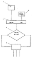
- the invention is in accordance with the method as well as in the manner according to the device in the Drawing shown and described in more detail below.
- the drawing shows the essential furnishings according to the device in such Linkage that also the procedure according to the invention can be seen therefrom.
- a speed sensor. 1 On the vehicle, which is not shown here, is a speed sensor. 1 arranged. This is located in the front of the vehicle and is either as Infrared sensor arrangement or as a radar signal arrangement or as an ultrasonic arrangement executed. In all three versions, according to the Doppler principle, the speed of the oncoming vehicle or the relative speed of the two themselves towards one another or the relative speed of a vehicle a standing object. Furthermore, a sound sensor 2 is somewhere sound-proof arranged on the shell of the vehicle. The impact generated in the shell a specific sound, according to the knowledge gained, which led to the invention has, frequency and amplitude of the mass ratio of the colliding vehicles, and depends on further parameters.
- the sound sensor 2 is so on the shell of the Vehicle arranged that a sound connection is given and any Structure-borne sound acting on or generated by the shell from the bodywork Sound sensor is detected directly.
- the shell itself is solid Welded joints or forced connection elements throughout sound conclusive. Therefore, it is theoretically irrelevant at which point the sound sensor is arranged. However, to rule out malfunction, it is appropriate to this to the load-bearing elements of the shell, the frontal deformation are relatively violently exposed.
- Both signals are read into an electronics 3 and conditioned accordingly.
- the speed signal is, for example, with the help of their own Tachometer signals the relative speed determined and possibly set in proportion.
- Out the sound sensor signal 2 a corresponding resolvable signal is created, already within the first half period, the edges and the amplitude are evaluated.
- the processed in this logic unit of the electronics 2 electronic information are subsequently fed to a valuation unit 4, in which, for example, limit values or signal threshold values are stored, exceeding one or the other Occupant protection system or possibly all occupant protection systems are triggered together.
- This rating can be either in the form of pure thresholds, the factory or be subsequently set, be fixed or it may be a limited number of be deposited as a data field so-called patterns. It can be a limited number given pattern, for example, given speed and Amplitudensignalmay be stored, the one or the other accident situations represent. Depending on this, either only the belt tensioning system or else the belt tensioning system can be activated together with the airbag system. Further Occupant protection systems are possible, which are also dependent on the severity of the Accident are selectively activated.
- this device or these process-appropriate leads Approach to a very fast deployment of a qualified Decision criterion on whether and which occupant protection systems are activated should.
- the triggering of the actual signal in the case of a maximum crash occurs more short-term than is possible with most conventional inertial sensors.
- the accident as such can be qualified at an extremely early stage of the time.
Landscapes
- Engineering & Computer Science (AREA)
- Mechanical Engineering (AREA)
- Air Bags (AREA)
- Automotive Seat Belt Assembly (AREA)
Description
Die Erfindung betrifft ein Verfahren sowie eine Einrichtung zum Aktivieren von Insassenschutzsystemen in Kraftfahrzeugen bei Unfällen, bei welchem die Schutzsysteme abhängig von Sensorschwellwerten aktiviert werden.The invention relates to a method and a device for activating Occupant protection systems in motor vehicles in accidents, in which the protection systems be activated depending on sensor thresholds.
Die mittlerweile grundsätzlich verwendeten Insassenschutzsysteme wie Airbag und darüber hinaus auch Rückhaltesysteme wie Gurtstraffer und dergleichen, werden im Falle eines Aufprallunfalles aktiviert. Die Aktivierung erfolgt dabei in den meisten Fällen durch sogenannte Trägheitssensoren. Diese Trägheitssensoren bestehen aus Masseelementen, die bei Verschiebung durch Beschleunigung, bzw. Negativbeschleunigung, eine Ortsveränderung ausführen. Diese Ortsveränderung wird in verschiedener Weise detektiert bzw. als Signal umgesetzt. Überschreiten dabei die Beschleunigungen und die daraus resultierenden Massenverschiebungen vorbestimmbare Grenzwerte, so führt dies zur Auslösung der oben genannten Insassenschutzsysteme, von denen Airbag und Gurtstraffsysteme die bekanntesten sind.The now generally used occupant protection systems such as airbags and above In addition, restraint systems such as belt tensioners and the like, in the case of Impact accident activated. The activation takes place in most cases by so-called inertial sensors. These inertial sensors consist of mass elements, when shifted by acceleration, or negative acceleration, a Change location. This change of location is detected in various ways or implemented as a signal. Exceed the accelerations and the resulting resulting mass shifts predeterminable limits, this leads to Activation of the above occupant protection systems, of which airbags and Belt tensioning systems are the best known.
So ist aus der DE-OS 38 34 005 ein Trägheitssensor bekannt, bei dem eine träge Masse auf einer Ebene angeordnet ist. Diese träge Masse ist mit einem Seil verbunden und das Seil ist wiederum mit einer drehbaren Zahnscheibe verbunden. Bei Verzögerung bzw. Beschleunigung wird die träge Masse bewegt und führt über das Seil eine Drehbeaufschlagung der Zahnscheibe herbei. Die Zahnscheibe wiederum ist im Lichtstrahl einer Lichtschranke, so daß die durch die Drehung bewirkten periodischen Unterbrechungen ein von der Drehgeschwindigkeit der Zahnscheibe abhängiges Frequenzsignal liefert. Dies führt zu einer Bewertbarkeit der auf die träge Masse wirkenden Beschleunigung. Thus, from DE-OS 38 34 005, an inertial sensor is known in which an inertial mass a level is arranged. This inertial mass is connected to a rope and the rope is in turn connected to a rotatable toothed disc. In case of delay or Acceleration, the inertial mass is moved and leads over the rope one Turning on the toothed disk. The toothed disk is in the light beam a photocell, so that the periodic interruptions caused by the rotation provides a dependent of the rotational speed of the toothed pulley frequency signal. This leads to an evaluation of the acceleration acting on the inertial mass.
Die US-A-4 842 301 offenbart einen akustischen Crash-Sensor für Kraftfahrzeuge. Aus dem aufgenommenen Signal wird ein Interessierender Frequenzbereich ausgefiltert. Das resultierende Signal wird mit einem Schwellwert verglichen. Sobald der Schwellwert eine vorbestimmte Zeit überschritten ist, wird ein entsprechendes Schutzsignal ausgelöst.US-A-4 842 301 discloses an automotive acoustic crash sensor. Out The received signal is filtered out of an interesting frequency range. The resulting signal is compared with a threshold. Once the threshold one predetermined time is exceeded, a corresponding protection signal is triggered.
Alternativ ist aus der EP-A-0 728 628 ein Verfahren bekannt, bei welchem die Relativgeschwindigkeit zwischen Hindernis und Fahrzeug ermittelt und ausschließlich daraus eine Unfallbewertung erstellt wird.Alternatively, from EP-A-0 728 628 a method is known in which the Relative speed between obstacle and vehicle determined and exclusive An accident assessment is created from this.
Diese Verfahren zielen auf eine jeweilige Reaktion der Sicherheitssysteme im Fahrzeug ab. These methods aim at a respective reaction of the safety systems in the vehicle from.
Es ist weiterhin bekannt, daß die gesamten Insassenschutzsysteme innerhalb weniger Millisekunden ausgelöst bzw. aktiviert werden müssen. Auch ein Aufprallunfall aus hoher Geschwindigkeit läuft, zumindest was die Deformationszeit der Fahrgastzelle betrifft, in Millisekunden bzw. mindestens Sekundenbruchteilen, ab. Auslösendes Element bleibt aber nach wie vor der eigentliche sogenannte Crash-Sensor. Der Crash-Sensor als solches detektiert den Unfall in derjenigen Zeitphase, in der der Aufprall bereits stattgefunden hat und die Deformation der Fahrgastzelle beginnt. Erst zu diesem Zeitpunkt wird dem Fahrzeug eine Negativbeschleunigung aufgeprägt, die der Sensor erfassen kann. Die Verwendung von trägen Massen und entsprechenden Anlenkmitteln hat sich jedoch in vielen Fällen als zu langsam erwiesen. Die Schnelligkeit der Bewertung des Aufpralles ist jedoch ausschlaggebend für eine sichere Aktivierung der Insassenschutzsysteme.It is further known that the entire occupant protection systems within less Milliseconds must be triggered or activated. Also a crash accident of high Speed runs, at least as far as the deformation time of the passenger compartment is concerned, in Milliseconds or at least split seconds, from. The triggering element remains as before the actual so-called crash sensor. The crash sensor as such detects the accident in the time phase in which the impact has already occurred and the deformation of the passenger compartment begins. Only at this time will the vehicle imprinted a negative acceleration, which can detect the sensor. The usage of inert masses and corresponding Anlenkmitteln but has in many cases as to slowly proved. However, the speed of the assessment of the impact is crucial for safe activation of occupant protection systems.
So sind aus der DE 32 05 560 A 1 induktive Beschleunigungssensoren bekannt, die versuchen, das Signal direkter abzugreifen. Jedoch auch hier muß mit entsprechenden beweglichen Massen gearbeitet werden.Thus, from DE 32 05 560 A1 inductive acceleration sensors are known which try to tap the signal more directly. However also here must with appropriate moving masses are worked.
Aus der DE 40 40 572 A 1 sowie weiteren Schriften sind eine Vielzahl von Trägheits- und Beschleunigungssensoren bekannt, die jedoch aufgrund beweglicher Teile und einer entsprechend komplizierten Anlenkung zu langsam sind.From DE 40 40 572 A 1 and other writings are a variety of inertial and Acceleration sensors known, however, due to moving parts and a according to complicated articulation are too slow.
Aus der EP 04 84 895 B 1 ist ein Ultraschall-Abstandsmeßverfahren bekannt. Dieses Abstandsmeßverfahren ist zur Verkehrsüberwachung eingesetzt und überwacht sich dem Fahrzeug relativ bewegende Hindernisse, wie vorausfahrende Fahrzeuge oder dergleichen in einem bestimmten Raum bzw. Zeitfenster. Der Einsatz hierbei ist lediglich auf Verkehrsüberwachungsmaßnahmen eingerichtet. Eine Verwendung wird dieses Ultraschallabstandsmeßverfahrens in Verbindung mit der Aktivierung von Insassenschutzsystemen ist in dieser vorgeschlagenen Verfahrensweise hierbei ungeeignet.From EP 04 84 895 B 1 an ultrasonic distance measuring method is known. This Distance measurement is used for traffic monitoring and monitors the Vehicle relatively moving obstacles, such as vehicles in front or the like in a given room or time window. The use here is only on Traffic monitoring measures set up. One use will be this Ultraschallabstandsmeßverfahrens in connection with the activation of Occupant protection systems is in this case unsuitable in this proposed procedure.
Der Erfindung liegt somit die Aufgabe zugrunde, ein Verfahren sowie eine Einrichtung der gattungsgemäßen Art dahingehend weiterzubilden, daß zum einen die Insassenschutzsysteme frühzeitiger aktivierbar sind und zum anderen ebenso schnell eine Information über die Schwere des zu erwartenden Aufpralles zur Einleitung bzw. Aktivierung entsprechender Maßnahmen bzw. Einrichtungen gegeben ist. The invention is therefore based on the object, a method and a device of further develop generic type such that on the one hand the Occupant protection systems are activated earlier and on the other just as fast one Information about the severity of the expected impact for initiation or activation appropriate measures or facilities is given.
Die gestellte Aufgabe wird erfindungsgemäß durch die Verfahrensschritte des Anspruches 1 gelöst.The stated object is achieved according to the invention solved by the method steps of claim 1.
Hinsichtlich der Einrichtung der gattungsgemäßen Art wird die gestellte Aufgabe erfindungsgemäß durch die kennzeichnenden Merkmale des Anspruches 7 gelöst.With regard to the device of the generic type is the task solved according to the invention by the characterizing features of claim 7.
Vorteilhafte Ausgestaltungen des erfindungsgemäßen Verfahrens sind in den Ansprüchen 2
bis 6 angegeben, und vorteilhafte Ausgestaltungen der erfindungsgemäßen Einrichtung sind
in den übrigen Ansprüchen angegeben.Advantageous embodiments of the method according to the invention are in the
Das Wesen der verfahrensgemäßen Erfindung besteht in der Bestimmung folgender
Größen,
Die Parameter der Geschwindigkeit werden aus der Relativgeschwindigkeit ermittelt. Zum einen liegt die eigene Fahrzeuggeschwindigkeit über das eigene Tachometersystem vor, und zum anderen wird aus der Relativgeschwindigkeit die beispielsweise durch Infrarot, Radar oder Ultraschallsendung nach dem Dopplerprinzip ermittelt wird, gebildet. D. h., daß das Geschwindigkeitssignal bereits vor der Kollision vorliegt, und zur Aufnahme dieses Signales keine wertvolle Zeit während des Unfalles vergeudet wird. Die zweite zusätzliche erfindungsgemäße Maßnahme besteht darin, das Verhältnis der aufeinanderprallenden Massen zu bestimmen. Dies beruht auf der Erkenntnis, daß aus Relativgeschwindigkeit und dem Massenverhältnis der aufeinanderprallenden Fahrzeuge oder Gegenstände die Schwere des Unfalles eindeutig bestimmbar ist. Dabei wird die Masse durch eine Frequenz bzw. Amplitudenmessung derjenigen Schallschwingung ermittelt, die beim Aufprall am eigenen Fahrzeug entsteht. Und zwar ist dabei die Schallschwingung gemeint, die am Rohbau bzw. der Rohkarosse des eigenen Fahrzeuges beim Aufprall entsteht. Wichtig ist hierbei, daß ein wesentlicher Unterschied darin besteht, Beschleunigungs- oder Deformationssensoren nicht zu verwenden. In der Erfindung wird die Schallschwingung am Rohbau des eigenen Fahrzeuges gemessen. Amplitude und ggf. auch die Frequenz dieser Schwingung spiegeln das Masseverhältnis der aufeinanderprallenden Fahrzeuge, bzw. Fahrzeug und Gegenstände, wieder. Daraus kann die Schwere des Aufpralles als solches bzw. die für die Deformation nun vorliegenden Energie ermittelt werden. Der erhebliche Vorteil ist, daß eine solche Information bereits nach der ersten vollzogenen Schallschwingung bzw. nach der ersten oder ggf. sogar nach der halben ersten Schwingungsperiode vorliegt. Der Körperschall des Rohbaus, der beim Aufprall erzeugt wird, liegt dabei zwar im hörbaren Schallspektrum, jedoch hat die maßgebliche Schwingung eine Periodendauer von einer oder weniger Millisekunden. Die Information über den Schallgeber liegt in einer extrem frühen Zeitphase des Unfalles vor. Die ggf. zu korrelierende Relativgeschwindigkeit liegt bereits vor dem Unfall vor.The parameters of the speed are determined from the relative speed. To the one is the own vehicle speed over the own speedometer system, and on the other hand, from the relative speed, for example, by infrared, Radar or ultrasonic transmission is determined according to the Doppler principle formed. That is, that the speed signal is present before the collision, and to record this Signals no valuable time is wasted during the accident. The second additional inventive measure is the ratio of the colliding Determine masses. This is based on the knowledge that from relative velocity and the mass ratio of the colliding vehicles or objects the Severity of the accident is clearly determinable. The mass is due to a frequency or amplitude measurement of that sound vibration, which is determined by the impact on the own vehicle is created. And that is the sound vibration meant that on Body shell or the body shell of the own vehicle on impact arises. Important is Here, that a major difference is acceleration or Not to use deformation sensors. In the invention, the sound vibration at Shell of own vehicle measured. Amplitude and possibly also the frequency of this Vibration reflect the mass ratio of the colliding vehicles, or Vehicle and objects, again. From this, the severity of the impact as such or the energy now available for the deformation can be determined. The considerable The advantage is that such information is already executed after the first one Sound vibration or after the first or possibly even after the first half Vibration period is present. The structure-borne sound of the shell, which is generated on impact, Although it lies in the audible sound spectrum, but the relevant vibration has a Period of one or less milliseconds. The information about the sounder is at an extremely early stage of the accident. The possibly correlated Relative speed is already present before the accident.
Abhängig von den so ermittelten Größen der Relativgeschwindigkeit und der Amplitude kann abhängig von darauf gesetzten Grenzwerten nun das ein oder andere Schutzsystem oder ggf. gleichzeitig alle Insassenschutzsysteme aktiviert werden.Depending on the variables of the relative velocity and the amplitude determined in this way Depending on the limit values set, one or the other protection system or if necessary, all occupant protection systems are activated at the same time.
Der Vorteil dieses erfindungsgemäßen Verfahrens liegt im wesentlichen darin, daß der Unfall als solches sehr schnell erfaßbar und darüber hinaus auch in der selben kurzen Zeit bereits bewertbar ist.The advantage of this method according to the invention lies essentially in the fact that the accident As such, it can be detected very quickly and, moreover, in the same short time already is assessable.
Einrichtungsgemäß wird hierbei über die entsprechend angegebenen Abstandssensoren ein oder mehrere Schallsensoren verwendet, die am Rohbau bzw. der Rohkarosse des Fahrzeuges befestigt sind. Diese sind von ihrem mechanischen Aufwand so einfach gestaltet bzw. gestaltbar, daß sie gegenüber den meisten anderen bekannten sogenannten Trägheitssensoren zuverlässiger arbeiten. Dies erhöht über die oben genannten funktionalen Vorteile auch die aktive Sicherheit und die ereignisabhängige Verfügbarkeit der einzelnen Insassenschutzsysteme.Furnishings are here via the appropriately specified distance sensors a or several sound sensors used in the shell or the body of the Vehicle are attached. These are so easy from their mechanical effort designed or gestaltungsbar that they compared to most other known so-called Inertia sensors work more reliably. This increases over the above functional Advantages include the active security and the event-dependent availability of the individual Occupant protection systems.
In weiterer vorteilhafter Ausgestaltung der Erfindung ist vorgegeben, daß die Geschwindigkeit durch Aussenden von Signalen und Empfangen von Reflexionssignalen nach dem Dopplerprinzip ermittelt wird. Die Ermittlung der Relativgeschwindigkeit sowie die Kenntnis der eigenen Fahrzeuggeschwindigkeit über die fahrzeuginterne Tachometereinrichtung, läßt die Bewertung einer Vielzahl von einzelnen Geschwindigkeiten, wie beispielsweise die eigene Geschwindigkeit, die Geschwindigkeit des entgegenkommenden Hindernisses oder des Fremdfahrzeuges, die sich daraus ergebende Relativgeschwindigkeit, sowie auch die Bewertung möglicherweise eines stehenden Hindernisses zu. Dabei wird, wie bereits gesagt, die nach dem Dopplerprinzip ermittelte Relativgeschwindigkeit mit der eigenen Geschwindigkeit korreliert.In a further advantageous embodiment of the invention is given that the Speed by sending signals and receiving reflection signals is determined according to the Doppler principle. The determination of the relative velocity and the Knowledge of the own vehicle speed over the in-vehicle Tachometer device, allows the evaluation of a variety of individual speeds, such as your own speed, the speed of the oncoming obstacle or of the other vehicle resulting therefrom Relative speed, as well as the rating may be a standing Obstacle too. Here, as already stated, the determined according to the Doppler principle Relative speed correlated with own speed.
In weiterer vorteilhafter Ausgestaltung des Verfahrens können verschiedene Methoden zweckmäßig sein, von denen sich drei Vorgehensweisen in Verbindung mit dem erfindungsgemäßen Verfahren als besonders zweckmäßig erwiesen haben. Dazu gehört die Geschwindigkeitsmessung über Infrarotstrahlung, über hochfrequente Radarsignale oder aber über Ultraschall. Diese drei Methoden bzw. Vorgehensweisen gewähren jeweils eine entsprechende zuverlässige Auswertung, die mit dem erfindungsgemäßen Verfahren gut kombinierbar ist.In a further advantageous embodiment of the method, various methods be appropriate, of which three approaches are related to the inventive method have been found to be particularly useful. This includes the Speed measurement via infrared radiation, via high-frequency radar signals or but about ultrasound. These three methods and procedures each grant one corresponding reliable evaluation, the well with the inventive method can be combined.
In weiterer vorteilhafter Ausgestaltung des erfindungsgemäßen Verfahrens wird bzw. werden in Abhängigkeit der Schwere der Kollision, die sich nach den oben genannten Maßgaben ermitteln läßt, entweder nur Gurtstraffsysteme oder Gurtstraffsysteme gemeinsam mit Airbag aktiviert. Weitere Insassenschutzsysteme sind denkbar, die dann ebenfalls, abhängig von der Schwere des Unfalles, entweder einzeln oder kumulativ ausgelöst werden.In a further advantageous embodiment of the method according to the invention is or will be depending on the severity of the collision, which varies according to the above specifications can determine, either only Gurtstraffsysteme or Gurtstraffsysteme together with Airbag activated. Other occupant protection systems are conceivable, which then also dependent be triggered by the severity of the accident, either individually or cumulatively.
Einrichtungsgemäß wird die gestellte Aufgabe dadurch gelöst, daß der Rohbau des Kraftfahrzeuges körperschallschlüssig mit einem Schallsensor verbunden ist, daß mindestens ein Sensor zur Erfassung der Geschwindigkeit bzw. der Relativgeschwindigkeit zu einem kollidierenden Fahrzeug oder Gegenstand vorgesehen ist, und daß über eine elektronische Bewertungseinheit die Schwere der Kollision ermittelbar und die Insassenschutzsysteme aktivierbar sind. Kern ist hierbei ebenfalls der erfindungsgemäße Gedanke, daß zum einen ein Körperschallsignal am Rohbau des Kraftfahrzeuges ermittelt wird und zum anderen die Relativgeschwindigkeit zum kollidierenden Fahrzeug oder Gegenstand ermittelt wird. Aus dem Körperschallsignal des Rohbaus kann bei Bewertung der Amplitude das Massenverhältnis der kollidierenden Massen bestimmt werden; auch die Auswertung der Frequenz liefert weitergehende Informationen. Sodann werden Geschwindigkeitssignal und Schallsignal miteinander korreliert und es kann daraus die Schwere des Unfalles ermittelt werden. Davon abhängig können sodann, wie oben bei der Offenbarung der verfahrensgemäßen Erfindung bereits dargestellt, die Insassenschutzsysteme entsprechend aktiviert werden. Einrichtungsgemäß the task is achieved in that the shell of the Motor vehicle is connected in a structure-borne sound with a sound sensor, that at least one sensor for detecting the speed or the relative speed is provided to a colliding vehicle or object, and that over a electronic assessment unit can determine the severity of the collision and the Occupant protection systems are activated. Core here is also the invention Thought that on the one hand detects a structure-borne noise signal on the shell of the motor vehicle and on the other hand the relative speed to the colliding vehicle or Item is determined. From the structure-borne sound signal of the carcass can at rating the amplitude of the mass ratio of the colliding masses are determined; also the Evaluation of the frequency provides further information. Then be Speed signal and sound signal correlated with each other and it can from the Severity of the accident can be determined. Dependent on it then can, as above with the Revelation of the inventive method already shown, the Occupant protection systems are activated accordingly.
Hierbei ist es besonders vorteilhaft, einen Schallsensor zu verwenden. Es hat sich gezeigt, daß, wie oben bereits dargestellt, ein entsprechenden Crash-Signal, bedingt durch die Deformation während des Aufpralles, bereits ein qualifiziertes und auswertbares Signal liefert, bereits innerhalb der ersten Schwingungsamplitude, ggf. sogar der ersten halben Periode. Der Abgriff eines solchen maßgeblichen Signales für die Aktivierung der Insassenschutzsysteme ist gegenüber herkömmlichen Trägheitssensoren deutlich zuverlässiger, da die Sensorgestaltung als solches einfacher ist.It is particularly advantageous to use a sound sensor. It has shown, that, as already shown above, a corresponding crash signal due to the Deformation during the impact, already a qualified and evaluable signal delivers, even within the first oscillation amplitude, possibly even the first half Period. The tap of such a significant signal for the activation of Occupant protection systems is clear compared to conventional inertial sensors more reliable, since the sensor design is easier as such.
Auf mechanisch bewegliche Teile kann gänzlich verzichtet werden, wenn Schallsensoren beispielsweise in piezoelektrischer Ausführung verwendet werden. Darüberhinaus liegt das Schaltsignal noch schneller vor, als dies Beschleunigungssensoren realisieren können, weil innerhalb des Sensors keine Massen mehr bewegt werden müssen.On mechanically moving parts can be completely dispensed with, if sound sensors be used for example in piezoelectric design. Beyond that, that lies Switch signal even faster before, as this acceleration sensors can realize, because no masses have to be moved within the sensor.
Da die Geschwindigkeit bzw. die Relativgeschwindigkeit bereits kurz vor dem Unfall bzw. der Kollision ermittelt wird, wird für diese Aktion keine kostbare Zeit während der Deformationsphase beim Unfall verdeudet. Obwohl letztendlich zwei Sensorsignale ausgewertet werden, bleibt das System extrem schnell.Since the speed or the relative speed already shortly before the accident or the Collision is detected, this action is not a precious time during the Deformation phase in the accident verdeudet. Although ultimately two sensor signals be evaluated, the system remains extremely fast.
Die Erfindung ist in verfahrensgemäßer sowie auch in einrichtungsgemäßer Weise in der Zeichnung dargestellt und nachfolgend noch näher beschrieben.The invention is in accordance with the method as well as in the manner according to the device in the Drawing shown and described in more detail below.
Die Zeichnung zeigt die wesentlichen einrichtungsgemäßen Elemente in einer derartigen Verknüpfung, daß auch die erfindungsgemäße Verfahrensweise daraus ersichtlich ist.The drawing shows the essential furnishings according to the device in such Linkage that also the procedure according to the invention can be seen therefrom.
Am Fahrzeug, welches hier nicht weiter dargestellt ist, ist ein Geschwindigkeitssensor 1
angeordnet. Dieser befindet sich im Frontbereich des Fahrzeuges und ist entweder als
Infrarotsensoranordnung oder als Radarsignalanordnung oder als Ultraschallanordnung
ausgeführt. In allen drei Versionen kann nach dem Doppler-Prinzip die Geschwindigkeit des
entgegenkommenden Fahrzeuges bzw. die Relativgeschwindigkeit der beiden sich
aufeinanderzubewegenden Fahrzeuge oder die Relativgeschwindigkeit eines Fahrzeuges zu
einem stehenden Gegenstand ermittelt werden. Desweiteren ist ein Schallsensor 2 irgendwo
schallschlüssig am Rohbau des Fahrzeuges angeordnet. Der Aufprall erzeugt im Rohbau
einen spezifischen Schall, wobei gemäß der gewonnen Erkenntnis, die zur Erfindung geführt
hat, Frequenz und Amplitude von dem Masseverhältnis der kollidierenden Fahrzeuge, und
weiteren Parametern abhängig ist. Der Schallsensor 2 ist dabei so an dem Rohbau des
Fahrzeuges angeordnet, daß eine schallschlüssige Verbindung gegeben ist und jedweder
Körperschall, der auf den Rohbau einwirkt oder von demselben erzeugt wird, vom
Schallsensor direkt erfaßbar ist. Der Rohbau selbst ist durch seine festen
Schweißverbindungen oder Zwangsverbindungselemente in sich durchgehend
schallschlüssig. Von daher ist es theoretisch unerheblich, an welcher Stelle der Schallsensor
angeordnet ist. Um jedoch Fehlfunktionen auszuschließen ist es zweckmäßig, diesen an den
tragenden Elementen des Rohbaus anzuordnen, die im Frontalbereich der Deformation
relativ heftig ausgesetzt sind.On the vehicle, which is not shown here, is a speed sensor. 1
arranged. This is located in the front of the vehicle and is either as
Infrared sensor arrangement or as a radar signal arrangement or as an ultrasonic arrangement
executed. In all three versions, according to the Doppler principle, the speed of the
oncoming vehicle or the relative speed of the two themselves
towards one another or the relative speed of a vehicle
a standing object. Furthermore, a
Beide Signale werden in eine Elektronik 3 eingelesen und entsprechend konditioniert. Aus
dem Geschwindigkeitssignal wird beispielsweise unter Zuhilfenahme des eigenen
Tachometersignales die Relativgeschwindigkeit ermittelt und ggf. ins Verhältnis gesetzt. Aus
dem Schallsensorsignal 2 wird ein entsprechendes auflösbares Signal erstellt, wobei bereits
innerhalb der ersten Halbperiode die Flanken und die Amplitude bewertet werden.Both signals are read into an
Die in dieser Logikeinheit der Elektronik 2 aufbereiteten elektronischen Informationen
werden hernach einer Bewertungseinheit 4 zugeführt, in welcher beispielsweise Grenzwerte
bzw. Signalschwellwerte abgelegt sind, bei deren Überschreitung das ein oder andere
Insassenschutzsystem oder ggf. alle Insassenschutzsysteme gemeinsam ausgelöst werden.
Diese Bewertung kann entweder in Form reiner Schwellwerte, die werksseitig oder
nachträglich einstellbar sind, festgelegt sein oder aber es können eine begrenzte Anzahl von
sogenannten Mustern als Datenfeld hinterlegt sein. Dabei können eine begrenzte Anzahl
vorgegebener Muster, beispielsweise vorgegebener Geschwindigkeits- und
Amplitudensignalverhältnisse abgelegt sein, die die ein oder andere Unfallsituationen
repräsentieren. Davon abhängig kann dann entweder nur das Gurtstraffsystem oder auch
das Gurtstraffsystem gemeinsam mit dem Airbagsystem aktiviert werden. Weitere
Insassenschutzsysteme sind möglich, die auch hierbei abhängig von der Schwere des
Unfalles selektiv aktivierbar sind.The processed in this logic unit of the
Wie oben bereits ausgeführt, führt diese Einrichtung bzw. diese verfahrensgemäße Vorgehensweise zu einer sehr schnellen Bereitstellung eines qualifizierten Entscheidungskriteriums darüber, ob und welche Insassenschutzsysteme aktiviert werden sollen. Auch die Auslösung des eigentlichen Signales im Falle eines Maximalcrashes erfolgt hierbei kurzfristiger, als dies bei den meisten herkömmlichen Trägheitssensoren möglich ist.As already stated above, this device or these process-appropriate leads Approach to a very fast deployment of a qualified Decision criterion on whether and which occupant protection systems are activated should. The triggering of the actual signal in the case of a maximum crash occurs more short-term than is possible with most conventional inertial sensors.
Darüber hinaus ist der Unfall als solches in einer extrem frühen Zeitphase qualifizierbar.Moreover, the accident as such can be qualified at an extremely early stage of the time.
Claims (14)
- Method for activating vehicle occupant protection systems in motor vehicles in the case of accidents, in which the protection systems are activated as a function of sensor threshold values, bya) measuring or determining the relative velocity dV of the driver's own vehicle with respect to a colliding vehicle or object before a collision,b) measuring the frequency and/or the amplitude A of the sound oscillation U which occurs directly at the shell of the vehicle as a result of the collision,c) determining a mass of the colliding vehicle or object from the measured frequency and/or amplitude of the sound oscillation U, andd) determining the severity of the collision from the relative velocity dV and the mass of the colliding vehicle or object and activating the protection systems when predefinable velocity and amplitude limiting values dVx and Ax are exceeded.
- Method for activating vehicle occupant protection systems according to Claim 1, characterized in that the relative velocity is determined by emitting signals and receiving reflective signals using the Doppler principle.
- Method for activating vehicle occupant protection systems according to Claim 1 or 2, characterized in that the relative velocity is measured using infrared radiation.
- Method for activating vehicle occupant protection systems according to Claim 1 or 2, characterized in that the relative velocity is measured using highfrequency radar signals.
- Method for activating vehicle occupant protection systems according to Claim 1 or 2, characterized in that the relative velocity is measured using ultrasonic sound.
- Method for activating vehicle occupant protection systems according to one or more of the preceding claims, characterized in that either only the seatbelt pretensioning system or the seatbelt pretensioning system together with the airbag are activated as a function of the severity of the collision.
- Method for activating vehicle occupant protection systems according to one or more of the preceding claims, characterized in that the severity of the collision is determined by comparing the relative velocity dV which is determined and the amplitude A with one or more stored patterns of given values, and in that the respective underlying limiting values dVx and Ax are determined from them in an ad hoc fashion.
- Device for activating vehicle occupant protection systems of a motor vehicle, having sensors (1, 2) by means of which the protection systems can be activated as a function of sensor threshold values in the case of accidents, one of the sensors being a sound sensor (2) which can be connected to the shell of the motor vehicle so as to pick up structure-borne sound signals, and another of the sensors is a sensor (1) for sensing the velocity or relative velocity with respect to a colliding vehicle or object, and an electronic evaluation unit (4) for determining a mass of the colliding vehicle or object from a frequency and/or amplitude of the sound oscillation which is detected by the sound sensor (2), and for also determining the severity of the collision from the sensed velocity or relative velocity and the determined mass, and for outputting corresponding activation signals to the vehicle occupant protection systems.
- Device for activating vehicle occupant protection systems in motor vehicles according to Claim 8, characterized in that the sound sensor (2) is arranged in the front region of the shell.
- Device for activating vehicle occupant protection systems in motor vehicles according to Claim 8 or 9, characterized in that the velocity sensor (1) is an infrared sensor or an RF radar sensor or an ultrasonic sound sensor.
- Device for activating vehicle occupant protection systems in motor vehicles according to one or more of the preceding claims, characterized in that the sensors (1, 2) are connected to an electronic unit (3) in such a way that a relative velocity signal can be determined from the velocity signal and the signal which is resolved over time can be determined from the sound signal.
- Device for activating vehicle occupant protection systems in motor vehicles according to one or more of the preceding claims, characterized in that the electronic unit (3) is connected to an electronic evaluation unit (4) in which the conditioned sensor signals dV and A can be compared with limiting values and when exceeded they generate the corresponding activation signals for the vehicle occupant protection systems (5).
- Device for activating vehicle occupant protection systems in motor vehicles, according to one or more of the preceding claims, characterized in that the electronic evaluation unit (4) is equipped with a memory element and a comparator.
- Device for activating vehicle occupant protection systems in motor vehicles, according to one or more of the preceding claims, characterized in that a non-volatile memory element is provided within the evaluation unit (4), in which memory element a data field which is provided with signal patterns dVi and Ai is stored.
Applications Claiming Priority (2)
| Application Number | Priority Date | Filing Date | Title |
|---|---|---|---|
| DE19742606 | 1997-09-26 | ||
| DE19742606A DE19742606B4 (en) | 1997-09-26 | 1997-09-26 | Method and device for activating occupant protection systems in motor vehicles |
Publications (3)
| Publication Number | Publication Date |
|---|---|
| EP0904989A2 EP0904989A2 (en) | 1999-03-31 |
| EP0904989A3 EP0904989A3 (en) | 2001-03-14 |
| EP0904989B1 true EP0904989B1 (en) | 2005-01-26 |
Family
ID=7843767
Family Applications (1)
| Application Number | Title | Priority Date | Filing Date |
|---|---|---|---|
| EP98115900A Expired - Lifetime EP0904989B1 (en) | 1997-09-26 | 1998-08-24 | Method and device for activating of passenger safety systems in vehicles |
Country Status (2)
| Country | Link |
|---|---|
| EP (1) | EP0904989B1 (en) |
| DE (2) | DE19742606B4 (en) |
Families Citing this family (14)
| Publication number | Priority date | Publication date | Assignee | Title |
|---|---|---|---|---|
| DE19913675B4 (en) * | 1999-03-25 | 2006-05-04 | Volkswagen Ag | Method and device for controlling a safety system in motor vehicles |
| DE19938891B4 (en) * | 1999-08-17 | 2010-04-22 | Continental Automotive Gmbh | Method and device for controlling the deployment of a motor vehicle occupant protection system |
| US6771166B2 (en) * | 2001-11-14 | 2004-08-03 | Motorola, Inc. | Air bag deployment sensing apparatus and method |
| DE10206351B4 (en) * | 2002-02-14 | 2004-08-05 | Daimlerchrysler Ag | Method and device for personal and collision protection on a vehicle |
| DE10234624B4 (en) * | 2002-07-29 | 2008-08-07 | Spies, Martin, Dipl.-Ing. (FH) | Passive safety system for motor vehicles with pre-crash sensor |
| DE10360138A1 (en) * | 2003-12-20 | 2005-07-21 | Daimlerchrysler Ag | Piezoelectric collision detector and safety equipment deployment system for vehicle, detects mass of object, e.g. pedestrian, with which collision occurs and activates appropriate safety device |
| DE10360769B4 (en) * | 2003-12-23 | 2012-04-12 | Conti Temic Microelectronic Gmbh | Method and device for triggering at least one occupant protection device in a vehicle |
| DE102004035738A1 (en) * | 2004-07-23 | 2005-09-15 | Siemens Ag | Device for release of person protection system in motor vehicle has sensing device with second sensor reacting to impact sound and sending out signal to evaluating means from which proving criterium can be determined |
| DE102004043597A1 (en) | 2004-09-06 | 2006-03-09 | Robert Bosch Gmbh | Device for detecting a collision of a vehicle with an obstacle |
| DE102005014013A1 (en) * | 2005-03-26 | 2006-09-28 | Conti Temic Microelectronic Gmbh | Vehicle sensor for e.g. passenger protection system of automobile, has measurement sensor with different direction-dependant sensing characteristics that are predetermined by its geometrical form and polarizations of piezoelectric material |
| DE102007061658A1 (en) | 2007-12-18 | 2009-06-25 | Adc Automotive Distance Control Systems Gmbh | Classification of the vehicle environment |
| DE102008039957A1 (en) | 2008-08-27 | 2010-03-04 | Continental Automotive Gmbh | Method for determining an accident severity criterion by means of an acceleration signal and a structure-borne sound signal |
| KR102587096B1 (en) * | 2019-02-22 | 2023-10-10 | 현대자동차주식회사 | Apparatus for detecting impact portion of vehicle and method thereof |
| CN118379832A (en) * | 2024-06-27 | 2024-07-23 | 山东冠县恒良管业有限公司 | Collision alarm system of highway guardrail plate |
Family Cites Families (26)
| Publication number | Priority date | Publication date | Assignee | Title |
|---|---|---|---|---|
| US3735398A (en) * | 1971-05-20 | 1973-05-22 | Sperry Rand Corp | Base band short range pre-collision sensor for actuation of vehicle safety apparatus |
| JPS4858533A (en) * | 1971-11-22 | 1973-08-16 | ||
| DE2922273A1 (en) * | 1979-05-31 | 1981-01-22 | Siemens Ag | Vehicle collision safety device with inflatable air bag - transmits ultrasonic beam ahead of vehicle to detect approaching obstacle |
| DE3001780C2 (en) * | 1980-01-18 | 1984-09-27 | Becker Autoradiowerk Gmbh, 7516 Karlsbad | Control arrangement for safety devices in vehicles |
| US4346914A (en) * | 1980-12-17 | 1982-08-31 | General Motors Corporation | Acoustic emission automotive crash sensor |
| DE3205560A1 (en) * | 1982-02-17 | 1983-08-25 | Ingenieurbüro für Industrietechnik Manfred Knüfelmann GmbH, 4000 Düsseldorf | Inductive accelerometer |
| DE3507381A1 (en) * | 1985-03-02 | 1986-09-04 | Bosch Gmbh Robert | DEVICE FOR PROTECTING VEHICLE VEHICLES IN ACCIDENTAL ACCIDENTS |
| DE3729019A1 (en) * | 1987-08-31 | 1989-03-16 | Messerschmitt Boelkow Blohm | DEVICE FOR RELEASING A SAFETY DEVICE |
| DE3733832A1 (en) * | 1987-10-07 | 1989-04-27 | Messerschmitt Boelkow Blohm | SENSOR FOR MOTOR VEHICLES |
| US4842301A (en) * | 1988-09-02 | 1989-06-27 | General Motors Corporation | Acoustic emission automotive crash sensor |
| DE3834005A1 (en) * | 1988-10-06 | 1990-04-19 | Schwant Wilfried Dipl Ing | Sensor for measuring changes in the speed of a vehicle, in particular a motor vehicle, in the event of a collision (impact) |
| US5216607A (en) * | 1989-05-30 | 1993-06-01 | Trw Vehicle Safety Systems Inc. | Method and apparatus for sensing a vehicle crash using energy and velocity as measures of crash violence |
| JPH0399957A (en) * | 1989-09-13 | 1991-04-25 | Fuji Heavy Ind Ltd | Forward vehicle detecting device |
| US5073860A (en) * | 1989-11-07 | 1991-12-17 | Trw Vehicle Safety Systems Inc. | Method and apparatus for sensing a vehicle crash in real time using frequency domain analysis |
| GB9004916D0 (en) * | 1990-03-05 | 1990-05-02 | Stresswave Tech | A collision detector for a vehicle |
| DE4035501A1 (en) * | 1990-11-08 | 1992-05-14 | Bosch Gmbh Robert | METHOD FOR DETERMINING THE RELATIVE POSITION OF VEHICLES IN ROAD TRANSPORT |
| DE4040572A1 (en) * | 1990-12-19 | 1992-06-25 | Bosch Gmbh Robert | METHOD FOR MEASURING THE DISTANCE AND SPEED OF AN OBJECT |
| JP2879613B2 (en) * | 1991-03-18 | 1999-04-05 | 本田技研工業株式会社 | Occupant protection device |
| DE9215382U1 (en) * | 1992-11-11 | 1994-03-17 | Siemens AG, 80333 München | Sound detector mounted in a vehicle |
| DE4323861C2 (en) * | 1993-07-16 | 1996-04-11 | Richard Lang | 4-point belt integrated in a vehicle seat |
| US5626359A (en) * | 1993-12-02 | 1997-05-06 | Trw Vehicle Safety Systems, Inc. | Method and apparatus for controlling an actuatable restraining device in response to discrete control zones |
| DE4426090C2 (en) * | 1994-01-14 | 1997-10-23 | Franz Mueller | Devices for protecting vehicle occupants and the body in a motor vehicle |
| DE4425846A1 (en) * | 1994-07-21 | 1996-01-25 | Telefunken Microelectron | Method for triggering side airbags of a passive safety device for motor vehicles |
| EP0728624A3 (en) * | 1995-02-24 | 1996-11-06 | Trw Inc | Method and apparatus for controlling an actuatable restraining device using predictive crash sensing |
| DE19520721C2 (en) * | 1995-06-12 | 1998-12-10 | Bsrs Restraint Syst Gmbh | Belt tensioner system of a passive restraint system for a motor vehicle |
| DE19644975B4 (en) * | 1995-10-31 | 2004-07-22 | Honda Giken Kogyo K.K. | Procedure for assessing a vehicle collision |
-
1997
- 1997-09-26 DE DE19742606A patent/DE19742606B4/en not_active Expired - Fee Related
-
1998
- 1998-08-24 DE DE59812510T patent/DE59812510D1/en not_active Expired - Lifetime
- 1998-08-24 EP EP98115900A patent/EP0904989B1/en not_active Expired - Lifetime
Also Published As
| Publication number | Publication date |
|---|---|
| EP0904989A3 (en) | 2001-03-14 |
| DE59812510D1 (en) | 2005-03-03 |
| DE19742606B4 (en) | 2005-09-15 |
| DE19742606A1 (en) | 1999-04-01 |
| EP0904989A2 (en) | 1999-03-31 |
Similar Documents
| Publication | Publication Date | Title |
|---|---|---|
| DE19848997B4 (en) | Vehicle occupant protection system | |
| EP1355805B1 (en) | Method for triggering means of restraint in a motor vehicle | |
| DE19743009B4 (en) | Method and apparatus for single point sensing of front and side impact crash conditions | |
| DE102005008190B4 (en) | Method and control device for triggering side impact restraint systems | |
| DE10132681C1 (en) | Method for classifying an obstacle using pre-crash sensor signals | |
| DE102004046360B4 (en) | Motor vehicle with a preventive protection system | |
| DE10049911B4 (en) | Method and device for activating occupant protection devices | |
| DE60200126T2 (en) | Device and method for checking an occupant protection device | |
| EP1261509B1 (en) | Method for detecting a rollover situation | |
| EP0842829A1 (en) | Trigger device for occupant restraint systems in a vehicle | |
| DE19742606B4 (en) | Method and device for activating occupant protection systems in motor vehicles | |
| EP1656282A1 (en) | Motor vehicle provided with a pre-safe system | |
| EP1523688A1 (en) | Device for monitoring the surroundings of a vehicle | |
| DE10202908B4 (en) | Method and arrangement for determining a detection range of a pre-crash sensor system | |
| DE10157203B4 (en) | Passive security system | |
| EP1542886B1 (en) | Method for the detection of an impact | |
| DE102008043637A1 (en) | Protection system e.g. active occupant protection system, activating and/or controlling method for use in motor vehicle, involves evaluating ambient situation and/or actual driving condition of vehicle to detect secondary crash | |
| DE10323483A1 (en) | Device for determining a relative speed between a vehicle and an impact object | |
| DE102004024265B4 (en) | Security system for operating at least one electrically operable closure device of a door of a vehicle | |
| EP1634099A2 (en) | Device for the classification of at least one object by means of an environment sensor | |
| EP0988180B1 (en) | Device for controlling a passenger protection device in a motor vehicle | |
| DE19753160C1 (en) | Arrangement for detecting an impending accident situation for a motor vehicle | |
| DE102005020146A1 (en) | Control unit for occupants and pedestrian protecting system at vehicle, comprising impact sensor and structure-borne sound detector | |
| EP1641655B1 (en) | Method for controlling an occupant protection device in a vehicle | |
| EP2244912A1 (en) | Method and controller for controlling safety means for a vehicle |
Legal Events
| Date | Code | Title | Description |
|---|---|---|---|
| PUAI | Public reference made under article 153(3) epc to a published international application that has entered the european phase |
Free format text: ORIGINAL CODE: 0009012 |
|
| AK | Designated contracting states |
Kind code of ref document: A2 Designated state(s): DE ES FR GB IT |
|
| AX | Request for extension of the european patent |
Free format text: AL;LT;LV;MK;RO;SI |
|
| PUAL | Search report despatched |
Free format text: ORIGINAL CODE: 0009013 |
|
| AK | Designated contracting states |
Kind code of ref document: A3 Designated state(s): AT BE CH CY DE DK ES FI FR GB GR IE IT LI LU MC NL PT SE |
|
| AX | Request for extension of the european patent |
Free format text: AL;LT;LV;MK;RO;SI |
|
| RIC1 | Information provided on ipc code assigned before grant |
Free format text: 7B 60R 21/00 A, 7G 01P 15/00 B, 7B 60R 21/01 B |
|
| 17P | Request for examination filed |
Effective date: 20010914 |
|
| AKX | Designation fees paid |
Free format text: DE ES FR GB IT |
|
| 17Q | First examination report despatched |
Effective date: 20020819 |
|
| GRAP | Despatch of communication of intention to grant a patent |
Free format text: ORIGINAL CODE: EPIDOSNIGR1 |
|
| GRAA | (expected) grant |
Free format text: ORIGINAL CODE: 0009210 |
|
| GRAS | Grant fee paid |
Free format text: ORIGINAL CODE: EPIDOSNIGR3 |
|
| AK | Designated contracting states |
Kind code of ref document: B1 Designated state(s): DE ES FR GB IT |
|
| PG25 | Lapsed in a contracting state [announced via postgrant information from national office to epo] |
Ref country code: IT Free format text: LAPSE BECAUSE OF FAILURE TO SUBMIT A TRANSLATION OF THE DESCRIPTION OR TO PAY THE FEE WITHIN THE PRESCRIBED TIME-LIMIT;WARNING: LAPSES OF ITALIAN PATENTS WITH EFFECTIVE DATE BEFORE 2007 MAY HAVE OCCURRED AT ANY TIME BEFORE 2007. THE CORRECT EFFECTIVE DATE MAY BE DIFFERENT FROM THE ONE RECORDED. Effective date: 20050126 Ref country code: GB Free format text: LAPSE BECAUSE OF FAILURE TO SUBMIT A TRANSLATION OF THE DESCRIPTION OR TO PAY THE FEE WITHIN THE PRESCRIBED TIME-LIMIT Effective date: 20050126 Ref country code: FR Free format text: LAPSE BECAUSE OF FAILURE TO SUBMIT A TRANSLATION OF THE DESCRIPTION OR TO PAY THE FEE WITHIN THE PRESCRIBED TIME-LIMIT Effective date: 20050126 |
|
| REG | Reference to a national code |
Ref country code: GB Ref legal event code: FG4D Free format text: NOT ENGLISH |
|
| REF | Corresponds to: |
Ref document number: 59812510 Country of ref document: DE Date of ref document: 20050303 Kind code of ref document: P |
|
| PG25 | Lapsed in a contracting state [announced via postgrant information from national office to epo] |
Ref country code: ES Free format text: LAPSE BECAUSE OF FAILURE TO SUBMIT A TRANSLATION OF THE DESCRIPTION OR TO PAY THE FEE WITHIN THE PRESCRIBED TIME-LIMIT Effective date: 20050507 |
|
| GBV | Gb: ep patent (uk) treated as always having been void in accordance with gb section 77(7)/1977 [no translation filed] |
Effective date: 20050126 |
|
| PLBE | No opposition filed within time limit |
Free format text: ORIGINAL CODE: 0009261 |
|
| STAA | Information on the status of an ep patent application or granted ep patent |
Free format text: STATUS: NO OPPOSITION FILED WITHIN TIME LIMIT |
|
| 26N | No opposition filed |
Effective date: 20051027 |
|
| EN | Fr: translation not filed | ||
| PGFP | Annual fee paid to national office [announced via postgrant information from national office to epo] |
Ref country code: DE Payment date: 20160831 Year of fee payment: 19 |
|
| REG | Reference to a national code |
Ref country code: DE Ref legal event code: R119 Ref document number: 59812510 Country of ref document: DE |
|
| PG25 | Lapsed in a contracting state [announced via postgrant information from national office to epo] |
Ref country code: DE Free format text: LAPSE BECAUSE OF NON-PAYMENT OF DUE FEES Effective date: 20180301 |