EP0904978B1 - Loading space for bulk material on transport vehicles. - Google Patents
Loading space for bulk material on transport vehicles. Download PDFInfo
- Publication number
- EP0904978B1 EP0904978B1 EP97116159A EP97116159A EP0904978B1 EP 0904978 B1 EP0904978 B1 EP 0904978B1 EP 97116159 A EP97116159 A EP 97116159A EP 97116159 A EP97116159 A EP 97116159A EP 0904978 B1 EP0904978 B1 EP 0904978B1
- Authority
- EP
- European Patent Office
- Prior art keywords
- loading
- loading space
- floor
- space
- suction
- Prior art date
- Legal status (The legal status is an assumption and is not a legal conclusion. Google has not performed a legal analysis and makes no representation as to the accuracy of the status listed.)
- Expired - Lifetime
Links
- 239000013590 bulk material Substances 0.000 title claims description 13
- 238000005192 partition Methods 0.000 claims description 20
- 238000002485 combustion reaction Methods 0.000 claims description 2
- 238000009434 installation Methods 0.000 claims description 2
- 239000002985 plastic film Substances 0.000 claims description 2
- 239000004753 textile Substances 0.000 claims description 2
- 238000011067 equilibration Methods 0.000 claims 1
- 239000002184 metal Substances 0.000 claims 1
- 239000007787 solid Substances 0.000 claims 1
- 239000000463 material Substances 0.000 abstract 3
- 239000011796 hollow space material Substances 0.000 abstract 2
- 239000007789 gas Substances 0.000 description 3
- 239000004033 plastic Substances 0.000 description 3
- 239000012530 fluid Substances 0.000 description 2
- 239000008187 granular material Substances 0.000 description 2
- 238000007664 blowing Methods 0.000 description 1
- 238000011109 contamination Methods 0.000 description 1
- 239000000428 dust Substances 0.000 description 1
- 239000004744 fabric Substances 0.000 description 1
- 239000000945 filler Substances 0.000 description 1
- 230000037431 insertion Effects 0.000 description 1
- 238000003780 insertion Methods 0.000 description 1
- 239000007788 liquid Substances 0.000 description 1
- 229920006327 polystyrene foam Polymers 0.000 description 1
- 239000000843 powder Substances 0.000 description 1
- 230000001737 promoting effect Effects 0.000 description 1
- 239000004460 silage Substances 0.000 description 1
Images
Classifications
-
- B—PERFORMING OPERATIONS; TRANSPORTING
- B60—VEHICLES IN GENERAL
- B60P—VEHICLES ADAPTED FOR LOAD TRANSPORTATION OR TO TRANSPORT, TO CARRY, OR TO COMPRISE SPECIAL LOADS OR OBJECTS
- B60P1/00—Vehicles predominantly for transporting loads and modified to facilitate loading, consolidating the load, or unloading
- B60P1/60—Vehicles predominantly for transporting loads and modified to facilitate loading, consolidating the load, or unloading using fluids, e.g. having direct contact between fluid and load
Definitions
- the invention relates to a loading space according to the preamble of the claim 1.
- WO 94/06648 is an insert for the transport of bulk goods in known a container.
- This insert consists of gas permeable and gas-impermeable layers as well as discharge and supply lines for gases. While or after loading, the bulk material introduced into the insert can be compressed by suction of air.
- a suction device should be available. If only at one directly at the suction opening arranged is sucked off, so remains a large, non-extractable remaining part in the cargo area. For that part to reduce, were already collecting pipes running across the loading area with inlet openings in the pipe walls. With these pipes the remaining portion could be reduced but not eliminated. If the remaining portion had to be removed manually, was this is due to the poor accessibility of the loading area and the hidden Areas of the pipes extremely tedious.
- silo In order to ensure a good exit behavior, it is also possible to do light Transport bulk goods in silo vehicles.
- the silo volume is however smaller than the maximum loading volume that can be achieved with a loading space. moreover the silo has to be lifted slightly on one side when emptying, to ensure that all bulk goods slide to the silo opening. Because the bulk material is often emptied in an interior at the destination, it is often not possible due to the structural conditions, the silo is sufficient to tend strongly.
- Other disadvantages of silos are that these have a high weight and a complex holding and actuating device need.
- a silo vehicle for the transport of dusty goods is in DE 30 21 869 A1.
- the vehicle can be pneumatic Conveyor be unloaded, using a suitable Attaching filters to the vehicle ensures that the cargo is decanted without dust a stand silo should be made possible.
- German patent application DE 1 024 883 describes a container vehicle for dusty or granular bulk goods with a drum-shaped, horizontal lying container.
- the container contents are unloaded by blowing of air under sloping shelves into a liquid-like one State shifted and squeezed out of the container like a liquid.
- the object of the invention is to find a simple solution, which ensures that bulk goods have the largest possible loading volume of a transport vehicle can be transported and that the Discharge is carried out as completely as possible with little effort.
- the floor of a cargo space is designed as a double floor, at that over a lower, essentially dense end surface and from a hole surface with through openings is arranged at a distance from it, so the bulk goods can be extracted from all areas of the cargo hold.
- the loading area or the perforated area is level and therefore easy to walk on, and there are no constricting areas where bulk goods get stuck can.
- the at least one outlet opening is with the intermediate space between the end and the perforated surface, so that the can be sucked out of the loading space through the outlet opening, the bulk material from the loading space through the through openings of the perforated surface got into the space.
- the perforated surface preferably consists of exchangeable perforated plates, so that the same loading space thanks to simple handles for the transport of bulk goods different grain sizes can be optimized by the respective bulk material adapted perforated sheets of different perforation diameters be used.
- the space is formed so that the suction line leading to the outlet opening can be connected, can completely empty the space.
- the space is preferably with at least one floor partition in at least two floor sub-rooms, each with an outlet opening divided.
- the floor partitions are essentially perpendicular to the perforated surface, and each part of the floor is bordered by part of the perforated area.
- a preferred subdivision provides that the floor partitions in the Run longitudinally or in the transverse direction of the cargo space and accordingly channel-shaped floor sub-spaces are formed.
- the outlet openings are arranged side by side, preferably directly into a transverse space serving as a suction area or longitudinal space, or possibly over - in particular root-shaped merging - pipelines connected to the suction area are.
- a transverse space serving as a suction area or longitudinal space, or possibly over - in particular root-shaped merging - pipelines connected to the suction area are.
- it may be in the range of Load space arranged a fan, which is connected on the suction side to the suction area is and has a delivery opening on the pressure side, which with a Delivery line is connectable.
- the blower is preferably electrical with a Three-phase drive, which must be connected to the mains, if necessary but also with a hydraulic or a combustion drive drivable.
- the suction power can be achieved with a fixed blower be achieved.
- the outlet openings that open into a common suction area can preferably by means of a controllable closure device be closed and opened so that the suction area with partial areas the hole surface is connectable. This can increase the full suction power a floor section can be created to completely empty it.
- each closed loading area is over an air balance connection, in particular at least one opening with a mesh or grid that has small openings, with the environment connectable.
- at least one cargo space partition arranged so that the cargo space in at least two cargo compartments are divided, each of which has at least one floor compartment is assigned, preferably each floor section only on connects a cargo compartment.
- each load compartment partition is made directly arranged over a floor partition.
- the cargo space is on the frame of a trailer, especially one EURO jumbo trailer as a particularly large-volume trailer version, one Trailer, a truck, a container, a swap body or if necessary also built a railroad car or a ship installation, the structure with fixed elements as a box body or, if necessary with textile or plastic sheeting as a tarpaulin structure.
- the drawing explains the invention using an exemplary embodiment.
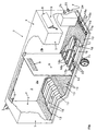
- the figure shows a perspective view of the cargo space with partial omitted areas.
- the cargo space 2 of the trailer 1 is outside of four walls 3 and a ceiling 4 completed in a box structure.
- the cargo space 2 is a cargo space partition 5, which is arranged transversely to the longitudinal direction of the loading space 2, in divided two cargo compartments 2a, 2b.
- two pipes 6 are arranged in the ceiling area, each of one Lead filling opening 7 into a loading compartment 2a, 2b.
- the floor of the loading space 2 is supported by a frame 10 with a wheel arrangement 11 worn and is designed as a double floor.
- a perforated bottom or perforated surface 13 is a lower end surface 12 arranged, which is provided with through openings 14.
- the size and distribution of the passage openings 14 is preferably towards that promotional product matched.
- polystyrene foam granulate have holes with a diameter of substantially Proven 10 mm.
- the holes are made in a grid, with a honeycomb Grid, each with a hole six - essentially the same Angular distances around the hole - nearest holes in a distance of essentially 100 mm are attached.
- an intermediate space is formed between the End surface 12 and the perforated surface 13, an intermediate space is formed.
- the intermediate space is preferably perpendicular to the end surface 12 arranged floor partitions 16 divided into sub-floors 15.
- Parallel channels are preferred, which are caused by the insertion of floor partitions 16 arise, which in the cargo space longitudinal, but possibly also in the transverse direction can run.
- At one end of the channels or the sub-floor spaces 15 is on each floor section 15 - or in a terminating one Bottom partition 16a, 16b, which is transverse to the other bottom partitions 1 6 runs - each formed an outlet opening 1 7a, 1 7b, the locked and opened by an actuatable closing member 18a, 18b can be.
- a mechanical, in particular, is preferably used as the closing member but fluidic, actuatable slide used, which has two fluid lines 19 can be pressurized according to the desired actuation is.
- the fluid lines 19 are below the end surface 12 connected to a pressure source via controllable valves.
- the valves are operated from a central controller 20, which is preferably at the rear of the Load space is arranged.
- the outlet openings 17a open directly into one Suction area 21, which is in the operational state as a closed space runs along the end faces of part of the channels or floor sub-spaces 15.
- the suction region 21 extends along the cargo area rear.
- the suction area in the area of the partition 5 or in the Longitudinal direction of the cargo space 2 is arranged, the channels then being transverse to get lost.
- the channels of the front cargo area are at the partition 5 with the outlet openings 17b and pipes 22 connected to the suction area 21.
- the closing members 18b of the outlet openings 17b are inserted into the pipes 22 in the area of the partition 5.
- the pipes are preferred rooted together, with changes in direction less than 60 °, preferably essentially 45 °, and the pipes are connected in pairs.
- the common pipeline 22 'preferably closes via a discharge opening 17a with a closure member 18a the suction area 21.
- the pipes 22 are in the space or in Floor compartments 15 of the rear cargo area arranged, with between the pipes 22 and the end surface 12 and the perforated surface 13 one free space is left in order not to allow bulk material to pass through hinder.
- this is at least provided with a connection opening to which the suction side a fan or a suction device can be connected.
- a blower not shown, in one small enclosed blower room 23 of the cargo space 2 arranged.
- the fan is connected to the suction area 21 via an intake port 24.
- a delivery opening leads from the blower out of the loading space 2.
- the blower can be operated from the central control 20.
- the blower is preferably driven by an electric motor that has a Electrical connection cable can be fed from the network. Because the bulk goods are close to the building can be expected with a mains connection.
- a volume of 100 m 3 can be loaded with bulk material with a loading space volume of 102 m 3 .
- a semi-trailer can also be designed with movable or insertable partition walls, in particular made of fabric or plastic sheets, so that the loading space can be adapted to the respective part quantities to be transported separately; the dividing walls are to be used above floor part space boundaries so that their contents can also be carried separately.
- a filling opening must be provided for every possible cargo compartment; if necessary, a flexible filler pipe, the inner opening of which can be assigned to different subspaces, can also be used.
- a door is used in case walls at least in one wall. In the case of tarpaulins, at least a partial area of a wall can be detached. Due to the flat perforated area, piece goods can also be easily transported in cargo compartments.
Landscapes
- Engineering & Computer Science (AREA)
- Transportation (AREA)
- Mechanical Engineering (AREA)
- Loading Or Unloading Of Vehicles (AREA)
- Fittings On The Vehicle Exterior For Carrying Loads, And Devices For Holding Or Mounting Articles (AREA)
- Air Transport Of Granular Materials (AREA)
- Control And Other Processes For Unpacking Of Materials (AREA)
- Catching Or Destruction (AREA)
- Handcart (AREA)
- Filling Or Emptying Of Bunkers, Hoppers, And Tanks (AREA)
Abstract
Description
Die Erfindung bezieht sich auf einen Laderaum nach dem Oberbegriff des Anspruches 1.The invention relates to a loading space according to the preamble of the claim 1.
Beim Transport von leichten Schüttgütern, wie etwa silierbarem Granulat oder Pulver, wird die mit einem Transportfahrzeug transportierbare Menge nicht durch das Gewicht, sondern durch das Volumen des Laderaumes beschränkt. Daher muss ein Transportfahrzeug für den effizienten Transport solcher Güter innerhalb der zulässigen Standard-Aussenmasse ein möglichst grosses Ladevolumen bereitstellen. Zudem ist es äusserst wichtig, dass das Befüllen und Entleeren mit minimalem Aufwand, schnell und jeweils so vollständig wie möglich erfolgen kann. Insbesondere nach dem Entleeren muss nämlich gewährleistet sein, dass im wesentlichen alles Schüttgut ausgetragen ist, so dass es beim anschliessenden Transport eines anderen Gutes nicht zu unerwünschten Verunreinigungen kommt. Bei einer einfachen Lösung wird auf einer normalen Ladefläche ein grosser Kunststoffsack bereitgestellt und dann mit Schüttgut befüllt. Am Bestimmungsort wird das Schüttgut mit einer Absaugvorrichtung des Bestimmungsortes aus dem Kunststoffsack abgesaugt. Mit den gängigen Säcken kann das mögliche Volumen auf der Ladefläche nicht vollständig ausgenützt werden. Zudem muss beim Entleeren, bzw. am Bestimmungsort eine von oben in den Sack einführbare Absaugvorrichtung vorhanden sein.When transporting light bulk goods, such as granulate or silage Powder is the amount that can be transported by a transport vehicle not limited by the weight, but by the volume of the cargo area. Therefore, a transport vehicle must be used for efficient transportation of such goods within the permissible standard external dimensions Provide a large loading volume. It is also extremely important that that Filling and emptying with minimal effort, quickly and so completely can be done as possible. Especially after emptying namely to be guaranteed that essentially all bulk goods are discharged is so that when it is subsequently transported another good there is no unwanted contamination. With a simple solution a large plastic bag is provided on a normal loading area and then filled with bulk goods. At the destination it will be Bulk material with a suction device of the destination from the Vacuumed plastic bag. With the usual bags, the possible volume not fully exploited on the loading area. In addition, must when emptying, or at the destination, an insertable from above into the sack Suction device should be available.
Aus der gattungsgemässen WO 94/06648 ist eine Einlage für den Transport von Schüttgut in einem Container bekannt. Diese Einlage besteht aus gasdurchlässigen und gasundurchlässigen Schichten sowie Ab- bzw. Zuleitungen für Gase. Während oder nach dem Beladen kann das in die Einlage eingebrachte Schüttgut durch Absaugen von Luft verdichtet werden. From the generic WO 94/06648 is an insert for the transport of bulk goods in known a container. This insert consists of gas permeable and gas-impermeable layers as well as discharge and supply lines for gases. While or after loading, the bulk material introduced into the insert can be compressed by suction of air.
Wenn das Schüttgut direkt in einen geschlossenen Laderaum gefüllt wird, kann wohl das ganze Volumen genützt werden, aber es ergeben sich dann beim Entleeren Probleme. Wie auch bei der Verwendung von Säcken muss eine Absaugvorrichtung vorhanden sein. Wenn lediglich an einer direkt bei der Ladefläche angeordneten Absaugöffnung abgesaugt wird, so bleibt ein zu grosser, nicht absaugbarer Restanteil im Laderaum zurück. Um diesen Anteil zu verkleinern, wurden schon über die Ladefläche verlaufende Sammelrohre mit Eintrittsöffnungen in den Rohrwänden eingesetzt. Mit diesen Rohren konnte der verbleibende Restanteil verkleinert, aber nicht beseitigt werden. Wenn nun der verbleibende Restanteil manuell beseitigt werden musste, war dies aufgrund der schlechten Begehbarkeit der Ladefläche und der versteckten Bereiche bei den Rohren äusserst mühsam.If the bulk goods are filled directly into a closed loading space, the entire volume can be used, but it then results problems with emptying. As with the use of sacks a suction device should be available. If only at one directly at the suction opening arranged is sucked off, so remains a large, non-extractable remaining part in the cargo area. For that part to reduce, were already collecting pipes running across the loading area with inlet openings in the pipe walls. With these pipes the remaining portion could be reduced but not eliminated. If the remaining portion had to be removed manually, was this is due to the poor accessibility of the loading area and the hidden Areas of the pipes extremely tedious.
Um ein gutes Austrittsverhalten zu gewährleisten, ist es auch möglich, leichtes Schüttgut in Silofahrzeugen zu transportieren. Das Silovolumen ist aber kleiner als das mit einem Laderaum erzielbare maximale Lade-Volumen. Zudem muss das Silo beim Entleeren auf der einen Seite etwas angehoben werden, um zu gewährleisten, dass alles Schüttgut zur Siloöffnung rutscht. Weil das Schüttgut am Bestimmungsort häufig in einem Innenraum entleert wird, ist es aufgrund der baulichen Verhältnisse häufig nicht möglich, das Silo genügend stark zu neigen. Weitere Nachteile von Silos bestehen darin, dass diese ein hohes Gewicht haben und eine aufwendige Halte- und Betätigungsvorrichtung benötigen.In order to ensure a good exit behavior, it is also possible to do light Transport bulk goods in silo vehicles. The silo volume is however smaller than the maximum loading volume that can be achieved with a loading space. moreover the silo has to be lifted slightly on one side when emptying, to ensure that all bulk goods slide to the silo opening. Because the bulk material is often emptied in an interior at the destination, it is often not possible due to the structural conditions, the silo is sufficient to tend strongly. Other disadvantages of silos are that these have a high weight and a complex holding and actuating device need.
Ein Beispiel für ein Silofahrzeug zum Transport staubförmiger Güter wird in der DE 30 21 869 A1 geoffenbart. Das Fahrzeug kann mit Hilfe einer pneumatischen Fördervorrichtung entladen werden, wobei durch eine geeignete Anbringung von Filtern am Fahrzeug ein staubfreies Umfüllen der Ladung in ein Standsilo ermöglicht werden soll.An example of a silo vehicle for the transport of dusty goods is in DE 30 21 869 A1. The vehicle can be pneumatic Conveyor be unloaded, using a suitable Attaching filters to the vehicle ensures that the cargo is decanted without dust a stand silo should be made possible.
In der US 5,199,826 wird ein LKW-Anhänger bzw. Auflieger zum Transport von Schüttgut gezeigt. Durch ein Kippen des Anhängers rutscht das Schüttgut zu einer Fördereinrichtung, die aus einer Zuleitung für Gase und einer Ableitung für das Schüttgut besteht und mittels einer Pumpe betrieben wird.In US 5,199,826 a truck trailer or semitrailer is used for transport of bulk goods shown. The bulk material slips when the trailer tilts to a conveyor consisting of a supply line for gases and a discharge line exists for the bulk material and is operated by means of a pump.
Die deutsche Auslegeschrift DE 1 024 883 beschreibt ein Behälterfahrzeug für staubförmiges oder körniges Schüttgut mit einem trommelförmigen, horizontal liegenden Behälter. Zum Entladen wird der Behälterinhalt durch Einblasen von Luft unter schräg geneigte Zwischenböden in einen flüssigkeitsähnlichen Zustand versetzt und wie eine Flüssigkeit aus dem Behälter hinausgedrückt.The German patent application DE 1 024 883 describes a container vehicle for dusty or granular bulk goods with a drum-shaped, horizontal lying container. The container contents are unloaded by blowing of air under sloping shelves into a liquid-like one State shifted and squeezed out of the container like a liquid.
Der Erfindung liegt nun die Aufgabe zugrunde, eine einfache Lösung zu finden, die gewährleistet, dass Schüttgut in einem möglichst grossen Ladevolumen eines Transportfahrzeuges transportiert werden kann und dass der Austrag mit kleinem Aufwand möglichst vollständig erfolgt.The object of the invention is to find a simple solution, which ensures that bulk goods have the largest possible loading volume of a transport vehicle can be transported and that the Discharge is carried out as completely as possible with little effort.
Diese Aufgabe wird durch die Merkmale des Anspruches 1 gelöst.This object is solved by the features of claim 1.
Wenn der Boden eines Laderaumes als doppelter Boden ausgebildet wird, bei dem über einer unteren, im wesentlichen dichten Abschlussfläche und von ihr beabstandet eine Lochfläche mit Durchtrittsöffnungen angeordnet ist, so kann das Schüttgut aus allen Bereichen des Laderaumes abgesaugt werden. Die Ladefläche, bzw. die Lochfläche ist eben und somit problemlos begehbar, und es gibt keine sich verengenden Bereiche, in denen sich Schüttgut festsetzen kann. Die mindestens eine Austrittsöffnung ist mit dem Zwischenraum zwischen der Abschluss- und der Lochfläche verbunden, so dass das durch die Austrittsöffnung aus dem Laderaum herausgesaugt werden kann, wobei das Schüttgut vom Laderaum durch die Durchtrittsöffnungen der Lochfläche in den Zwischenraum gelangt.If the floor of a cargo space is designed as a double floor, at that over a lower, essentially dense end surface and from a hole surface with through openings is arranged at a distance from it, so the bulk goods can be extracted from all areas of the cargo hold. The loading area or the perforated area is level and therefore easy to walk on, and there are no constricting areas where bulk goods get stuck can. The at least one outlet opening is with the intermediate space between the end and the perforated surface, so that the can be sucked out of the loading space through the outlet opening, the bulk material from the loading space through the through openings of the perforated surface got into the space.
Bevorzugt besteht die Lochfläche aus auswechselbaren Lochblechen, sodass derselbe Laderaum durch einfache Handgriffe für den Transport von Schüttgütern verschiedener Korngrösse dadurch optimiert werden kann, dass auf das jeweilige Schüttgut angepasste Lochbleche unterschiedlichen Lochdurchmessers eingesetzt werden.The perforated surface preferably consists of exchangeable perforated plates, so that the same loading space thanks to simple handles for the transport of bulk goods different grain sizes can be optimized by the respective bulk material adapted perforated sheets of different perforation diameters be used.
Der Zwischenraum wird so ausgebildet, dass die Saugleitung, die an die Austrittsöffnung anschliessbar ist, den Zwischenraum vollständig entleeren kann. Dazu wird der Zwischenraum vorzugsweise mit mindestens einer Bodentrennwand in mindestens zwei Bodenteilräume mit je einer Austrittsöffnung unterteilt. Die Bodentrennwände stehen im wesentlichen senkrecht zur Lochfläche, und jeder Bodenteilraum wird von einem Teil der Lochfläche berandet. Eine bevorzugte Unterteilung sieht vor, dass die Bodentrennwände in der Längs- oder aber in der Querrichtung des Laderaumes verlaufen und entsprechend kanalförmige Bodenteilräume gebildet werden. An den Stirnseiten der kanalförmigen Bodenteilräume sind nebeneinander die Austrittsöffnungen angeordnet, die vorzugsweise direkt in einen als Saugbereich dienenden Querraum bzw. Längsraum münden, oder gegebenenfalls über - insbesondere wurzelförmig zusammenführende - Rohrleitungen mit dem Saugbereich verbunden sind. Um die Saugleistung bereitzustellen, ist gegebenenfalls im Bereich des Laderaumes ein Gebläse angeordnet, das saugseitig an den Saugbereich angeschlossen ist und druckseitig eine Förderöffnung aufweist, die mit einer Förderleitung verbindbar ist. Das Gebläse ist vorzugsweise elektrisch mit einem Drehstromantrieb, der ans Stromnetz angeschlossen werden muss, gegebenenfalls aber auch mit einem Hydraulik- oder einem Verbrennungsantrieb antreibbar. Natürlich kann die Saugleistung aber mit einem ortsfesten Geläse erzielt werden. The space is formed so that the suction line leading to the outlet opening can be connected, can completely empty the space. For this purpose, the space is preferably with at least one floor partition in at least two floor sub-rooms, each with an outlet opening divided. The floor partitions are essentially perpendicular to the perforated surface, and each part of the floor is bordered by part of the perforated area. A preferred subdivision provides that the floor partitions in the Run longitudinally or in the transverse direction of the cargo space and accordingly channel-shaped floor sub-spaces are formed. On the front of the channel-shaped floor sections, the outlet openings are arranged side by side, preferably directly into a transverse space serving as a suction area or longitudinal space, or possibly over - in particular root-shaped merging - pipelines connected to the suction area are. In order to provide the suction power, it may be in the range of Load space arranged a fan, which is connected on the suction side to the suction area is and has a delivery opening on the pressure side, which with a Delivery line is connectable. The blower is preferably electrical with a Three-phase drive, which must be connected to the mains, if necessary but also with a hydraulic or a combustion drive drivable. Of course, the suction power can be achieved with a fixed blower be achieved.
Die Austrittsöffnungen, die in einen gemeinsamen Saugbereich münden, können vorzugsweise mittels einer steuerbaren Verschlussvorrichtung gezielt verschlossen und geöffnet werden, so dass der Saugbereich mit Teilbereichen der Lochfläche verbindbar ist. Dadurch kann die volle Saugleistung an einen Bodenteilraum angelegt werden, um diesen vollständig zu entleeren.The outlet openings that open into a common suction area can preferably by means of a controllable closure device be closed and opened so that the suction area with partial areas the hole surface is connectable. This can increase the full suction power a floor section can be created to completely empty it.
Um beim Befüllen und Entleeren eines geschlossenen Laderaumes den Aus- bzw. Eintritt von Luft zu ermöglichen, ist jeder geschlossene Ladebereich über eine Luftausgleich-Verbindung, insbesondere mindestens eine Öffnung mit einem Netz oder Gitter, das kleine Durchtrittsöffnungen hat, mit der Umgebung verbindbar. Um den Laderaum in Teilräume unterteilen zu können, ist mindestens eine Laderaumtrennwand so angeordnet, dass der Laderaum in mindestens zwei Ladeteilräume aufgeteilt wird, denen je mindestens ein Bodenteilraum zugeordnet ist, wobei vorzugsweise jeder Bodenteilraum nur an einen Ladeteilraum anschliesst. Dazu wird jede Laderaumtrennwand direkt über einer Bodentrennwand angeordnet.In order to ensure that the filling and emptying of a closed or to allow air to enter, each closed loading area is over an air balance connection, in particular at least one opening with a mesh or grid that has small openings, with the environment connectable. In order to be able to divide the cargo space into sub-spaces, at least one cargo space partition arranged so that the cargo space in at least two cargo compartments are divided, each of which has at least one floor compartment is assigned, preferably each floor section only on connects a cargo compartment. To do this, each load compartment partition is made directly arranged over a floor partition.
Der Laderaum ist auf dem Rahmen eines Aufliegers, insbesondere eines EURO-Jumboaufliegers als besonders grossvolumige Aufliegerversion, eines Anhängers, eines LKW's, eines Containers, einer Wechselbrücke oder gegebenenfalls auch eines Eisenbahnwagens oder eines Schiffs-Einbaus aufgebaut, wobei der Aufbau mit festen Elementen als Kofferaufbau oder gegebenenfalls mit Textil- oder Kunststoffbahnen als Planenaufbau ausgeführt ist.The cargo space is on the frame of a trailer, especially one EURO jumbo trailer as a particularly large-volume trailer version, one Trailer, a truck, a container, a swap body or if necessary also built a railroad car or a ship installation, the structure with fixed elements as a box body or, if necessary with textile or plastic sheeting as a tarpaulin structure.
Die Zeichnung erläutert die Erfindung anhand eines Ausführungsbeispieles.
Die Figur zeigt eine perspektivische Darstellung des Laderaumes mit teilweise
weggelassenen Flächen. Der Laderaum 2 des Aufliegers 1 ist aussen von
vier Wänden 3 und einer Decke 4 in Kofferaufbauweise abgeschlossen. In der
dargestellten Ausführungsform wird der Laderaum 2 von einer Laderaumtrennwand
5, die quer zur Längsrichtung des Laderaumes 2 angeordnet ist, in
zwei Ladeteilräume 2a, 2b unterteilt. Zur Befüllung der Ladeteilräume 2a, 2b
sind im Deckenbereich zwei Rohrleitungen 6 angeordnet, die je von einer
stirnseitigen Einfüllöffnung 7 in einen Ladeteilraum 2a, 2b führen. Damit die
beim Befüllen verdrängte Luft aus den Ladeteilräumen 2a, 2b austreten kann,
ist in der Laderaumtrennwand 5 und in der Heckwand 3 eine Öffnung mit einem
luftdurchlässigen Gitter 8 angeordnet. Das Gitter 8 der Heckwand ist mit
einer Klappe 9 verschliessbar. Beim Befüllen und Entleeren muss diese Klappe
9 geöffnet werden.The drawing explains the invention using an exemplary embodiment.
The figure shows a perspective view of the cargo space with partial
omitted areas. The
Der Boden des Laderaumes 2 wird von einem Rahmen 10 mit einer Radanordnung
11 getragen und ist als Doppelboden ausbildet. In einem Abstand über
einer unteren Abschlussfläche 12 ist ein Lochboden bzw. eine Lochfläche 13
angeordnet, der bzw. die mit Durchtrittsöffnungen 14 versehen ist. Die Grösse
und Verteilung der Durchtrittsöffnungen 14 wird vorzugsweise auf das zu
fördernde Produkt abgestimmt. In einer Ausführungsform für Polystyrolschaumgranulat
haben sich Bohrungen mit einem Durchmesser von im wesentlichen
10 mm bewährt. In einer bestimmten Ausführungsform der Erfindung
werden die Bohrungen rasterförmig angebracht, wobei etwa ein wabenartiger
Raster, bei dem je um eine Bohrung sechs - im wesentlichen in gleichen
Winkelabständen um die Bohrung verteilte - nächstliegende Bohrungen in
einem Abstand von im wesentlichen 100 mm angebracht sind. Zwischen der
Abschlussfläche 12 und der Lochfläche 13 ist ein Zwischenraum ausgebildet.
Der Zwischenraum wird vorzugsweise von senkrecht zur Abschlussfläche 12
angeordneten Bodentrennwänden 16 in Bodenteilräume 15 unterteilt.The floor of the
Bevorzugt sind Parallelkanäle, die durch das Einsetzen von Bodentrennwänden
16 entstehen, die in Laderaumlängs-, gegebenenfalls aber auch in Querrichtung
verlaufen können. An einem stirnseitigen Ende der Kanäle bzw. der Bodenteilräume
15 ist an jedem Bodenteilraum 15 - bzw. in einer diesen abschliessenden
Bodentrennwand 16a, 16b, die quer zu den anderen Bodentrennwänden
1 6 verläuft - je eine Austrittsöffnung 1 7a, 1 7b ausgebildet, die
von einem betätigbaren Schliessorgan 18a, 18b abgeschlossen und geöffnet
werden kann. Vorzugsweise wird als Schliessorgan ein mechanisch, insbesondere
aber fluidisch, betätigbarer Schieber eingesetzt, der über zwei Fluidleitungen
19 entsprechend der gewünschten Betätigung mit Druck beaufschlagbar
ist. Die Fluidleitungen 19 sind unterhalb der Abschlussfläche 12
über steuerbare Ventile mit einer Druckquelle verbunden. Die Ventile werden
von einer zentralen Steuerung 20 aus bedient, die vorzugsweise am Heck des
Laderaumes angeordnet ist. Die Austrittsöffnungen 17a münden direkt in einen
Saugbereich 21, der im betriebsbereiten Zustand als geschlossener Raum
entlang der Stirnseiten eines Teils der Kanäle bzw. Bodenteilräume 15 verläuft.
In der dargestellten Ausführungsform erstreckt sich der Saugbereich 21
entlang des Laderaumhecks. Es sind aber auch Ausführungsformen möglich,
bei denen der Saugbereich im Bereich der Trennwand 5 oder aber in der
Längsrichtung des Laderaumes 2 angeordnet ist, wobei dann die Kanäle quer
dazu verlaufen.Parallel channels are preferred, which are caused by the insertion of
Im dargestellten Beispiel sind die Kanäle des vorderen Laderaumbereiches bei
der Trennwand 5 über die Austrittsöffnungen 17b und Rohrleitungen 22 mit
dem Saugbereich 21 verbunden. Die Schliessorgane 18b der Austrittsöffnungen
17b sind im Bereich der Trennwand 5 in die Rohrleitungen 22 eingesetzt.
Um die Rohrleitungen zusammenzuführen und dabei aber Verstopfungsgefahren
im Knickbereich zu vermeiden, werden die Rohrleitungen vorzugsweise
wurzelförmig zusammengeführt, wobei die Richtungsänderungen weniger als
60°, vorzugsweise im wesentlichen 45°, betragen und die Rohrleitungen
paarweise verbunden sind. Die gemeinsame Rohrleitung 22' schliesst vorzugsweise
über eine Austrittsöffnung 17a mit einem Verschlussorgan 18a an
den Saugbereich 21 an. Die Rohrleitungen 22 sind im Zwischenraum bzw. in
Bodenteilräumen 15 des hinteren Laderaumbereiches angeordnet, wobei zwischen
den Rohrleitungen 22 und der Abschlussfläche 12 sowie der Lochfläche
13 je ein Freiraum belassen wird, um den Durchtritt von Schüttgut nicht zu
behindern.In the example shown, the channels of the front cargo area are at
the
Um den Saugbereich 21 mit einer Saugleistung beaufschlagen zu können, ist
dieser zumindest mit einer Anschlussöffnung versehen, an welche die Saugseite
eines Geläses bzw. einer Absaugvorrichtung anschliessbar ist. In der
dargestellten Ausführungsform ist ein nicht dargestelltes Gebläse in einem
kleinen abgeschlossenen Gebläseraum 23 des Laderaumes 2 angeordnet. Das
Geläse ist dabei über einen Ansaugstutzen 24 mit dem Saugbereich 21 verbunden.
Vom Geläse führt druckseitig eine Förderöffnung aus dem Laderaum
2. Das Gebläse ist von der zentralen Steuerung 20 aus bedienbar. Das Gebläse
wird vorzugsweise von einem Elektromotor angetrieben, der über ein
Elektroanschlusskabel vom Netz speisbar ist. Weil das Schüttgut in Gebäudenähe
entladen wird, kann mit einem Netzanschluss gerechnet werden.In order to be able to apply suction power to the suction area 21,
this is at least provided with a connection opening to which the suction side
a fan or a suction device can be connected. In the
The illustrated embodiment is a blower, not shown, in one
small enclosed blower room 23 of the
Mit dem erfindungsgemässen Auflieger kann bei einem Laderaumvolumen von 102 m3 ein Volumen von 100 m3 mit Schüttgut beladen werden. Zudem kann ein solcher Auflieger auch mit verschiebbaren oder einsetzbaren Trennwänden, insbesondere aus Stoff- oder Kunststoffbahnen, ausgebildet werden, so dass die Laderaumaufteilung den jeweiligen getrennt zu transportierenden Teilmengen angepasst werden kann; dabei sollen die Trennwände jeweils über Bodenteilraumgrenzen eingesetzt werden, damit deren Inhalte auch getrennt austragbar sind. Zum Befüllen muss für jeden möglichen Ladeteilraum eine Einfüllöffnung vorgesehen werden; gegebenenfalls kann auch ein flexibles Einfüllrohr, dessen innere Öffnung verschiedenen Teilräumen zugeordnet werden kann, eingesetzt werden. Um den Laderaum betretbar zu machen, ist bei Kofferwänden zumindest in einer Wand eine Tür eingesetzt. Bei Planen ist zumindest ein Teilbereich einer Wand lösbar. Aufgrund der ebenen Lochfläche können auch problemlos Stückgüter in Ladeteilräumen befördert werden.With the trailer according to the invention, a volume of 100 m 3 can be loaded with bulk material with a loading space volume of 102 m 3 . In addition, such a semi-trailer can also be designed with movable or insertable partition walls, in particular made of fabric or plastic sheets, so that the loading space can be adapted to the respective part quantities to be transported separately; the dividing walls are to be used above floor part space boundaries so that their contents can also be carried separately. For filling, a filling opening must be provided for every possible cargo compartment; if necessary, a flexible filler pipe, the inner opening of which can be assigned to different subspaces, can also be used. In order to make the loading space accessible, a door is used in case walls at least in one wall. In the case of tarpaulins, at least a partial area of a wall can be detached. Due to the flat perforated area, piece goods can also be easily transported in cargo compartments.
Claims (10)
- Loading space (2) for bulk material on a transport vehicle (1), comprising at least one closed loading region (2a, 2b) which can be filled through at least one filling orifice (7) and emptied through at least one outlet orifice and is closed at the bottom by a floor, characterized in that the floor is a double floor in which a perforated surface (13) which preferably consists of interchangeable perforated metal sheets and has passages (14) is arranged above a lower closure surface (12) and a distance away from it, at least one outlet orifice (17a, 17b) being connected to the intermediate space between the closure surface (12) and the perforated surface (13), through which outlet orifice bulk material can be sucked out of the loading space (2), the bulk material passing from the loading space (2) through the passages (14) of the perforated surface (13) into the intermediate space.
- Loading space according to Claim 1, characterized in that at least one floor partition (16), but preferably a plurality of floor partitions (16) is or are arranged between the closure surface (12) and the perforated surface (13) in such a way that the intermediate space is divided into at least two partial floor spaces (15), which are each bordered by a part of the perforated surface (13), each partial floor space (15) being connected to an outlet orifice (17a, 17b).
- Loading space according to Claim 2, characterized in that the outlet orifices (17a, 17b) open into a common suction region (21) and a controllable closure device (18a, 18b, 19, 20) for alternatively closing and opening the desired outlet orifices (17a, 17b) is preferably provided so that the suction region (21) can be connected to sections of the perforated surface (13).
- Loading space according to Claim 3, characterized in that the closure device (18a, 18b, 19, 20) at each outlet orifice (17a, 17b) comprises a closure member (18a, 18b), in particular a slide valve, which member or which valve optionally can be operated mechanically, but preferably fluidically - hydraulically or pneumatically, operation preferably being effected from a central control (20).
- Loading space according to Claim 3 or 4, characterized in that a blower is connected on the suction side to the suction region (21) and has, on the pressure side, a delivery orifice (25) which can be connected to a delivery line, the fan preferably being capable of being driven electrically by a three-phase drive which must be connected to the mains power supply, but optionally also capable of being driven by a hydraulic or an internal combustion drive.
- Loading space according to any of Claims 2 to 5, characterized in that the floor partitions (16) run in the longitudinal direction or in the transverse direction of the loading space (2) and accordingly form channel-like floor sections (15) at whose end faces one outlet orifice (17a, 17b) each is arranged side by side, which outlet orifices (17a, 17b) in particular open directly into a transverse space or longitudinal space serving as suction region (21) or optionally are connected via pipelines (22), in particular pipelines (22) converging in the manner of a root, to the suction region (21).
- Loading space according to any of Claims 2 to 6, characterized in that each closed loading region (2a, 2b) can be connected to the environment via an air equilibration connection, in particular at least one orifice having a net or grating (8) which has small passages.
- Loading space according to any of Claims 2 to 7, characterized in that at least one loading space partition (5) is arranged in the loading space (2) in such a way that the loading space (2) is divided into at least two loading sections (2a, 2b), each of which is coordinated with a floor section (15), each floor section (15) preferably being coordinated with only one of the at least two loading sections (2a, 2b).
- Loading space according to Claim 8, characterized in that the filling orifices (7) of all loading sections (2a, 2b) are arranged directly side by side, and that filling pipes (6) lead from the filling orifices (7) into the respective loading sections (2a, 2b).
- Loading space according to any of Claims 1 to 8, characterized in that the loading space (2) is mounted on the frame of a semitrailer, in particular of a EURO Jumbo semitrailer, of a trailer, of a truck, of a container, of a swap body or optionally of a railway wagon or of an interior ship's installation, the superstructure being produced as a box-type superstructure using solid elements or optionally as a tarpaulin superstructure using textile or plastic sheets.
Priority Applications (6)
| Application Number | Priority Date | Filing Date | Title |
|---|---|---|---|
| DE59709401T DE59709401D1 (en) | 1997-09-17 | 1997-09-17 | Loading space of a transport vehicle for bulk goods |
| EP97116159A EP0904978B1 (en) | 1997-09-17 | 1997-09-17 | Loading space for bulk material on transport vehicles. |
| AT97116159T ATE233187T1 (en) | 1997-09-17 | 1997-09-17 | LOADING COMPARTMENT OF A TRANSPORT VEHICLE FOR BULK GOODS |
| CZ982946A CZ294698A3 (en) | 1997-09-17 | 1998-09-15 | Loading space of a transport vehicle for bulk material |
| HU9802115A HU219965B (en) | 1997-09-17 | 1998-09-17 | Loading area of freight vehicle for bulk-goods |
| PL98328649A PL328649A1 (en) | 1997-09-17 | 1998-09-17 | Load carrying body a vehicle for transporting bulk particulate materials |
Applications Claiming Priority (1)
| Application Number | Priority Date | Filing Date | Title |
|---|---|---|---|
| EP97116159A EP0904978B1 (en) | 1997-09-17 | 1997-09-17 | Loading space for bulk material on transport vehicles. |
Publications (2)
| Publication Number | Publication Date |
|---|---|
| EP0904978A1 EP0904978A1 (en) | 1999-03-31 |
| EP0904978B1 true EP0904978B1 (en) | 2003-02-26 |
Family
ID=8227363
Family Applications (1)
| Application Number | Title | Priority Date | Filing Date |
|---|---|---|---|
| EP97116159A Expired - Lifetime EP0904978B1 (en) | 1997-09-17 | 1997-09-17 | Loading space for bulk material on transport vehicles. |
Country Status (6)
| Country | Link |
|---|---|
| EP (1) | EP0904978B1 (en) |
| AT (1) | ATE233187T1 (en) |
| CZ (1) | CZ294698A3 (en) |
| DE (1) | DE59709401D1 (en) |
| HU (1) | HU219965B (en) |
| PL (1) | PL328649A1 (en) |
Families Citing this family (2)
| Publication number | Priority date | Publication date | Assignee | Title |
|---|---|---|---|---|
| FR3011208B1 (en) * | 2013-09-30 | 2017-02-10 | Aspir | SYSTEM FOR RECOVERING AND STORING CONTENT AND VEHICLE EQUIPPED WITH SUCH A SYSTEM |
| IT202300022323A1 (en) | 2023-10-25 | 2025-04-25 | Grotti Srl | SUCTION DEVICE FOR MILLED MATERIAL, EQUIPMENT FOR SCARIFYING AND SUCTION OF RELATED MILLED MATERIAL, AND RESPECTIVE PROCEDURE |
Family Cites Families (6)
| Publication number | Priority date | Publication date | Assignee | Title |
|---|---|---|---|---|
| DE1024883B (en) * | 1955-10-04 | 1958-02-20 | Ver Westdeutsche Waggonfab | Container vehicle for dusty or granular bulk goods |
| WO1981000555A1 (en) * | 1979-08-28 | 1981-03-05 | A Jensen | A method and a system for pneumatically conveying a granular material out of a drying store |
| DE3021869A1 (en) * | 1980-06-11 | 1981-12-24 | Werner 4354 Datteln Knippenberg | Filter operating system for silo vehicle - uses multiple connections with control valves for pneumatic discharge and filter cleaning |
| EP0053412B1 (en) * | 1980-12-02 | 1985-03-06 | Shell Internationale Researchmaatschappij B.V. | Storage vessel for granular or particulate solid |
| US5199826A (en) * | 1992-02-14 | 1993-04-06 | Lawrence James C | Pump unloading trailer container for powdered bulk material |
| WO1994006648A1 (en) * | 1992-09-24 | 1994-03-31 | Podd Stephen D | Container aeration/vaccum liner pads and liner systems |
-
1997
- 1997-09-17 AT AT97116159T patent/ATE233187T1/en not_active IP Right Cessation
- 1997-09-17 DE DE59709401T patent/DE59709401D1/en not_active Expired - Fee Related
- 1997-09-17 EP EP97116159A patent/EP0904978B1/en not_active Expired - Lifetime
-
1998
- 1998-09-15 CZ CZ982946A patent/CZ294698A3/en unknown
- 1998-09-17 HU HU9802115A patent/HU219965B/en not_active IP Right Cessation
- 1998-09-17 PL PL98328649A patent/PL328649A1/en unknown
Also Published As
| Publication number | Publication date |
|---|---|
| EP0904978A1 (en) | 1999-03-31 |
| ATE233187T1 (en) | 2003-03-15 |
| CZ294698A3 (en) | 1999-04-14 |
| DE59709401D1 (en) | 2003-04-03 |
| HU9802115D0 (en) | 1998-11-30 |
| HUP9802115A3 (en) | 2000-04-28 |
| HUP9802115A2 (en) | 1999-03-29 |
| HU219965B (en) | 2001-10-28 |
| PL328649A1 (en) | 1999-03-29 |
Similar Documents
| Publication | Publication Date | Title |
|---|---|---|
| DE69017395T2 (en) | Portable vacuum cleaning system. | |
| DE60001621T2 (en) | Container lining with shifting means to facilitate the unloading of the container contents | |
| DE60128381T2 (en) | SYSTEN AND METHOD FOR UNLOADING BULK TANK FILLED WITH POWDER PRODUCT | |
| EP0904978B1 (en) | Loading space for bulk material on transport vehicles. | |
| DE7532419U (en) | DEVICE FOR EMPTYING BULK GOODS FROM CONTAINERS | |
| DE102013004401B4 (en) | Transport container and transport vehicle | |
| EP2133234B1 (en) | Variable storage space for transport and/or storage of goods | |
| DE2308029A1 (en) | VEHICLE FOR TRANSPORTING GOODS OF DIFFERENT KINDS | |
| DE3447125C2 (en) | ||
| EP0036962A2 (en) | Tube-like inlet for filling and emptying bulk containers | |
| DE2248154C3 (en) | Device for emptying bulk goods from transport containers | |
| DE102008056134B4 (en) | Container for bulk material | |
| DE4437614C2 (en) | Transport container for a truck for the transport of dry sludge | |
| EP3287316B1 (en) | Adapter for transforming a dump truck and dump truck | |
| DE8628334U1 (en) | Device for storing and dispensing powdery to dusty bulk material | |
| DE69109735T2 (en) | Device for extracting gas from a tank container. | |
| EP1552982A2 (en) | Load transporting vehicle | |
| DE3013418A1 (en) | Transport vehicle for granular loads - has gravity fed chamber with compressed air drive | |
| DE2822052C2 (en) | Device for transporting and storing different goods in the same container | |
| DE1901372A1 (en) | Material discharge device for container | |
| AT220552B (en) | Long container for storing or transporting bulk goods with a built-in emptying device | |
| DE102005044245A1 (en) | Filler device for e.g. cargo container, has chamber filled with flowable medium e.g. gas medium, where area of device is designed such that bulk goods placed on device are partly pushed towards chamber | |
| CH471027A (en) | Transport containers for bulk goods, on trucks or trailers | |
| DE9313365U1 (en) | Flexible transport container | |
| DE102009060769A1 (en) | Body for use in e.g. disposal vehicle for transporting waste oil, has transportation tank secured at chassis, solid and/or bulk material container movably arranged above transportation tank, and tilting device associated to container |
Legal Events
| Date | Code | Title | Description |
|---|---|---|---|
| PUAI | Public reference made under article 153(3) epc to a published international application that has entered the european phase |
Free format text: ORIGINAL CODE: 0009012 |
|
| AK | Designated contracting states |
Kind code of ref document: A1 Designated state(s): AT BE CH DE DK ES FI FR GB IT LI LU MC NL PT SE |
|
| AX | Request for extension of the european patent |
Free format text: AL;LT;LV;RO;SI |
|
| 17P | Request for examination filed |
Effective date: 19990930 |
|
| AKX | Designation fees paid |
Free format text: AT BE CH DE DK ES FI FR GB GR IE IT LI LU MC NL |
|
| RAP3 | Party data changed (applicant data changed or rights of an application transferred) |
Owner name: GASS INTERNATIONAL LOGISTICS GMBH & CO. KG |
|
| RBV | Designated contracting states (corrected) |
Designated state(s): AT BE CH DE DK ES FI FR GB IT LI LU MC NL PT SE |
|
| 17Q | First examination report despatched |
Effective date: 20011029 |
|
| GRAH | Despatch of communication of intention to grant a patent |
Free format text: ORIGINAL CODE: EPIDOS IGRA |
|
| GRAH | Despatch of communication of intention to grant a patent |
Free format text: ORIGINAL CODE: EPIDOS IGRA |
|
| GRAA | (expected) grant |
Free format text: ORIGINAL CODE: 0009210 |
|
| AK | Designated contracting states |
Designated state(s): AT BE CH DE DK ES FI FR GB IT LI LU MC NL PT SE |
|
| PG25 | Lapsed in a contracting state [announced via postgrant information from national office to epo] |
Ref country code: NL Free format text: LAPSE BECAUSE OF FAILURE TO SUBMIT A TRANSLATION OF THE DESCRIPTION OR TO PAY THE FEE WITHIN THE PRESCRIBED TIME-LIMIT Effective date: 20030226 Ref country code: IT Free format text: LAPSE BECAUSE OF FAILURE TO SUBMIT A TRANSLATION OF THE DESCRIPTION OR TO PAY THE FEE WITHIN THE PRE;WARNING: LAPSES OF ITALIAN PATENTS WITH EFFECTIVE DATE BEFORE 2007 MAY HAVE OCCURRED AT ANY TIME BEFORE 2007. THE CORRECT EFFECTIVE DATE MAY BE DIFFERENT FROM THE ONE RECORDED.SCRIBED TIME-LIMIT Effective date: 20030226 Ref country code: GB Free format text: LAPSE BECAUSE OF FAILURE TO SUBMIT A TRANSLATION OF THE DESCRIPTION OR TO PAY THE FEE WITHIN THE PRESCRIBED TIME-LIMIT Effective date: 20030226 Ref country code: FR Free format text: LAPSE BECAUSE OF NON-PAYMENT OF DUE FEES Effective date: 20030226 Ref country code: FI Free format text: LAPSE BECAUSE OF FAILURE TO SUBMIT A TRANSLATION OF THE DESCRIPTION OR TO PAY THE FEE WITHIN THE PRESCRIBED TIME-LIMIT Effective date: 20030226 |
|
| REG | Reference to a national code |
Ref country code: GB Ref legal event code: FG4D Free format text: NOT ENGLISH |
|
| REG | Reference to a national code |
Ref country code: CH Ref legal event code: EP |
|
| REF | Corresponds to: |
Ref document number: 59709401 Country of ref document: DE Date of ref document: 20030403 Kind code of ref document: P |
|
| PG25 | Lapsed in a contracting state [announced via postgrant information from national office to epo] |
Ref country code: SE Free format text: LAPSE BECAUSE OF FAILURE TO SUBMIT A TRANSLATION OF THE DESCRIPTION OR TO PAY THE FEE WITHIN THE PRESCRIBED TIME-LIMIT Effective date: 20030526 Ref country code: PT Free format text: LAPSE BECAUSE OF FAILURE TO SUBMIT A TRANSLATION OF THE DESCRIPTION OR TO PAY THE FEE WITHIN THE PRESCRIBED TIME-LIMIT Effective date: 20030526 Ref country code: DK Free format text: LAPSE BECAUSE OF FAILURE TO SUBMIT A TRANSLATION OF THE DESCRIPTION OR TO PAY THE FEE WITHIN THE PRESCRIBED TIME-LIMIT Effective date: 20030526 |
|
| PGFP | Annual fee paid to national office [announced via postgrant information from national office to epo] |
Ref country code: GB Payment date: 20030710 Year of fee payment: 7 |
|
| NLV1 | Nl: lapsed or annulled due to failure to fulfill the requirements of art. 29p and 29m of the patents act | ||
| GBV | Gb: ep patent (uk) treated as always having been void in accordance with gb section 77(7)/1977 [no translation filed] |
Effective date: 20030226 |
|
| PG25 | Lapsed in a contracting state [announced via postgrant information from national office to epo] |
Ref country code: ES Free format text: LAPSE BECAUSE OF FAILURE TO SUBMIT A TRANSLATION OF THE DESCRIPTION OR TO PAY THE FEE WITHIN THE PRESCRIBED TIME-LIMIT Effective date: 20030828 |
|
| PG25 | Lapsed in a contracting state [announced via postgrant information from national office to epo] |
Ref country code: LU Free format text: LAPSE BECAUSE OF NON-PAYMENT OF DUE FEES Effective date: 20030917 Ref country code: AT Free format text: LAPSE BECAUSE OF NON-PAYMENT OF DUE FEES Effective date: 20030917 |
|
| PG25 | Lapsed in a contracting state [announced via postgrant information from national office to epo] |
Ref country code: MC Free format text: LAPSE BECAUSE OF NON-PAYMENT OF DUE FEES Effective date: 20030930 Ref country code: LI Free format text: LAPSE BECAUSE OF NON-PAYMENT OF DUE FEES Effective date: 20030930 Ref country code: CH Free format text: LAPSE BECAUSE OF NON-PAYMENT OF DUE FEES Effective date: 20030930 Ref country code: BE Free format text: LAPSE BECAUSE OF NON-PAYMENT OF DUE FEES Effective date: 20030930 |
|
| PLBE | No opposition filed within time limit |
Free format text: ORIGINAL CODE: 0009261 |
|
| STAA | Information on the status of an ep patent application or granted ep patent |
Free format text: STATUS: NO OPPOSITION FILED WITHIN TIME LIMIT |
|
| EN | Fr: translation not filed | ||
| 26N | No opposition filed |
Effective date: 20031127 |
|
| BERE | Be: lapsed |
Owner name: *GASS INTERNATIONAL LOGISTICS G.M.B.H. & CO. K.G. Effective date: 20030930 |
|
| PG25 | Lapsed in a contracting state [announced via postgrant information from national office to epo] |
Ref country code: DE Free format text: LAPSE BECAUSE OF NON-PAYMENT OF DUE FEES Effective date: 20040401 |
|
| REG | Reference to a national code |
Ref country code: CH Ref legal event code: PL |