EP0904941A2 - Printer for print medium and ink ribbon cartridge for use in a printer - Google Patents
Printer for print medium and ink ribbon cartridge for use in a printer Download PDFInfo
- Publication number
- EP0904941A2 EP0904941A2 EP98115024A EP98115024A EP0904941A2 EP 0904941 A2 EP0904941 A2 EP 0904941A2 EP 98115024 A EP98115024 A EP 98115024A EP 98115024 A EP98115024 A EP 98115024A EP 0904941 A2 EP0904941 A2 EP 0904941A2
- Authority
- EP
- European Patent Office
- Prior art keywords
- ribbon
- section
- ribbon cassette
- printing
- printer
- Prior art date
- Legal status (The legal status is an assumption and is not a legal conclusion. Google has not performed a legal analysis and makes no representation as to the accuracy of the status listed.)
- Granted
Links
Images

Classifications
-
- B—PERFORMING OPERATIONS; TRANSPORTING
- B41—PRINTING; LINING MACHINES; TYPEWRITERS; STAMPS
- B41J—TYPEWRITERS; SELECTIVE PRINTING MECHANISMS, i.e. MECHANISMS PRINTING OTHERWISE THAN FROM A FORME; CORRECTION OF TYPOGRAPHICAL ERRORS
- B41J32/00—Ink-ribbon cartridges
- B41J32/02—Ink-ribbon cartridges for endless ribbons
-
- B—PERFORMING OPERATIONS; TRANSPORTING
- B41—PRINTING; LINING MACHINES; TYPEWRITERS; STAMPS
- B41J—TYPEWRITERS; SELECTIVE PRINTING MECHANISMS, i.e. MECHANISMS PRINTING OTHERWISE THAN FROM A FORME; CORRECTION OF TYPOGRAPHICAL ERRORS
- B41J35/00—Other apparatus or arrangements associated with, or incorporated in, ink-ribbon mechanisms
- B41J35/04—Ink-ribbon guides
Definitions
- the invention relates to a printer for recording media, with one across the transport path of the record carrier extending pressure beam, with at least one approximately over the entire length of the pressure beam extending ribbon cassette for recording and Transporting an endless ribbon, the two on their opposite End arranged deflector has between which is a section of ribbon outside the cassette runs, and with a between the pressure bar and the Ribbon cassette arranged, parallel to the print bar Movable printing device that a needle printhead for Printing on the record carrier and a guide device has a portion of the ribbon section passes the needle printhead.
- a ribbon cartridge for use in a printer Such a printer and one usable therein Ribbon cartridges are known from US 3 977 512.
- a printer of the type mentioned is used for printing of recording media such as individual sheets of paper, Continuous paper webs or fanfold paper webs used.
- recording media such as individual sheets of paper, Continuous paper webs or fanfold paper webs used.
- the pressure bar is usually made of metal manufactured profile element, whose at the back of the Record carrier adjacent printing surface with a elastic coating is provided.
- the Printer a ribbon cartridge in which an ink soaked Continuous ribbon is recorded, with the ink of the Recording medium is printed.
- the well-known ribbon cassette usually spans the entire Length of the pressure beam and has the pressure beam on it facing front two at their opposite Deflection elements arranged at the ends, for example arms or rollers, between which a ribbon section of the Continuous ribbon is stretched outside the cassette.
- the Ribbon Within the ribbon is layered in a meandering pattern and passed through a device in which is soaked in ink.
- the Printer transports one with the drive of the printer coupled transport device on the ribbon cassette the ribbon continuously through the ribbon cartridge through it.
- Between the print bar and the ribbon cassette is also a movable parallel to the pressure bar Arranged printing device that a printhead like one Needle print head or a type wheel print head used to print on the record carrier. To do this by means of a guide device provided on the printing device a portion of the outside of the Ribbon cassette arranged ribbon section on Printhead passed.
- the individual needles or types of Printhead according to image data supplied to the printer the ribbon against the one against the pressure bar Record carrier.
- the invention has for its object a printer or to specify a ribbon cassette of the type mentioned at the outset, in which the ribbon is soiled is protected.
- This task is solved for a printer in that the ribbon section running outside the ribbon cassette seen from the pressure bar behind the needle print head lies, and that on the needle printhead a housing is provided for the guide device in which the Section of the ribbon section is guided and that one facing the pressure bar in front of the printing device Opening that has the section of the ribbon section released for printing. Furthermore, the task by an ink ribbon cassette with the features of the claim 9 solved. Advantageous further developments result itself from the dependent subclaims.
- the outside of the ribbon cassette running ribbon section with the greatest possible distance held to the print bar when the ribbon cassette is inserted in the printer. Dust that accumulates during the transport of the record carrier through the printer from the recording medium in the area of the pressure bar triggers, due to the large distance of the Ribbon section to the print bar only negligible to a small extent up to the ribbon section. At the same time, this prevents the printer from working on the printer provided housing a contamination of the near the pressure beam held in the guide device Section of the ribbon.
- the ribbon section To protect against pollution is at least one near the outside of the ribbon cartridge running ribbon section, arranged above the same Provide web that is parallel to the pressure beam runs and with one of its narrow sides to the pressure beam shows. Through this additional web, the area between the printing device and the ribbon cassette protected from paper dust despite the large Distance to the ribbon section. Further is it is possible to add another web below the ribbon section to provide.
- the web is rectangular in cross section, with its other narrow side on a pressure bar facing Front of the ribbon cassette attached and stands perpendicular from this. By attaching the web directly on the ribbon cassette, for example Glue or by integrating the web with the ribbon cassette is formed, the web is replaced with every replacement the ribbon cassette with replaced. Another It is possible to arrange the web in the printer in attaching the bar to the frame of the printer.
- the printer has the guide device on the side facing away from the pressure beam Back of the printing device two rotatably mounted Guide rollers and two on both sides of the needle print head arranged, pivotally mounted, in front of the needle print head arranged section of the ribbon section exciting wings.
- One of the two leadership roles directs the section of the ribbon section in the housing of the guide device.
- the other of the two guide rollers leads the section from the Casing.
- the use is rotatably mounted Guide rollers advantageous because the continuous ribbon underneath comparatively low tensile forces in the pressure device redirected and issued by this.
- To the To further increase the positional accuracy of the section is also proposed at the management facility additionally between each leadership role and that to provide a further guide role for the adjacent rocker.
- the ribbon becomes through these additional guide rollers defined held to the wings.
- Both the first Leadership roles as well as the other leadership roles can be cylindrical or barrel-shaped be.
- the Ribbon section with such a small distance to the Ribbon section facing the front of the ribbon cassette, that with the ribbon cartridge installed in the printer seen from the pressure bar behind the printing device lies, causing soiling of the continuous ribbon is prevented.
- the two deflection elements on the opposite Ends of the ribbon cartridge preferably on the the front facing the ribbon section rotatably mounted Pulleys.
- the axes of rotation of the pulleys run parallel in this preferred embodiment to the front of the ribbon cartridge and are vertical aligned to the longitudinal direction of the ribbon section. Due to the rotatable bearing of the pulleys and their symmetrical arrangement to the longitudinal direction of the ribbon section the continuous ribbon is comparatively exposed to low tensile forces, increasing the lifespan of the continuous ribbon is increased.
- pulleys can also be used, the rounded arms free ends parallel to the front of the ribbon cartridge and perpendicular to the longitudinal direction of the ribbon section run.
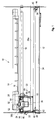
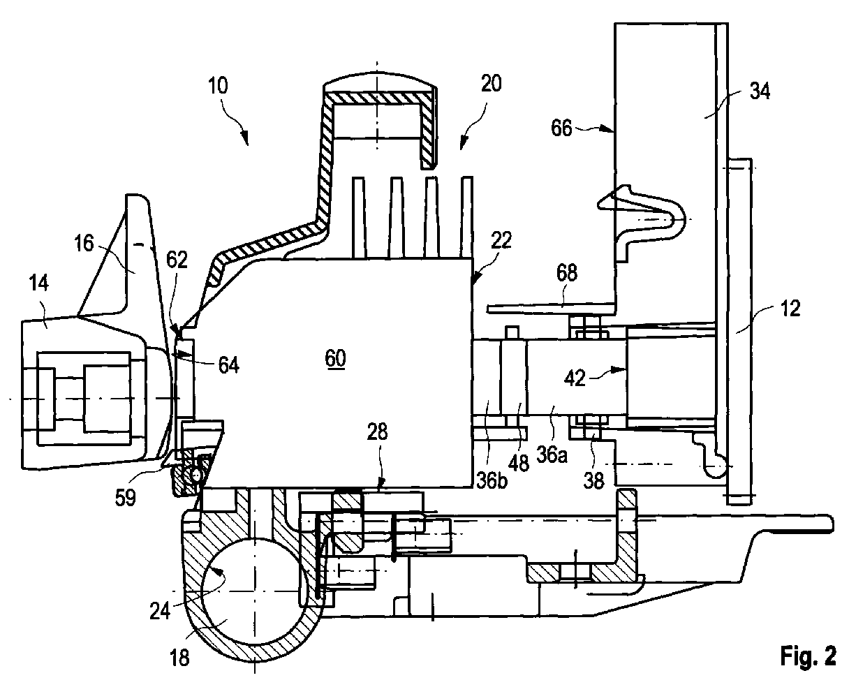
- FIGS. 1 and 2 show a printer 10 for printing of recording media such as single sheets of paper or continuous paper webs. For reasons of clarity are only components in FIGS. 1 and 2 of the printer 10, which is essential for the invention are.
- the printer 10 has a frame 12 that is only partially is shown, a transport device arranged in the frame 12 (not shown) and a controller (not shown).
- On frame 12 is made of aluminum manufactured pressure beam 14 attached, which is transverse to Direction of transport of the record carrier extends.
- the Pressure beam 14 is a hollow section with a rectangular cross section educated. There is one on its upper face inclined at an angle of about 5 ° to the pressure beam 14 Guide bar 16 formed in one piece, the Record carrier on the pressure bar 14 leads.
- Parallel to The pressure beam 14 on the frame 12 is round in cross section Guide 18 attached, along which a printing device 20 traversable across the transport path of the record carrier is.
- the printing device 20 has a print head carrier 22, the guide bushings 24 and 26 on the Guide 18 is slidably mounted.
- the print head carrier 22 has a carrier plate 28, on the top a needle print head 30 is attached centrally, the needle guide 32 faces the pressure bar 14.
- an ink ribbon cassette 34 Seen from the pressure bar 14 behind the printing device 20 is on the frame 12 by locking means (not shown) an ink ribbon cassette 34 is attached.
- the ribbon cartridge 34 runs parallel to the pressure beam 14 and extends over its entire length.
- an endless ink ribbon 36 is recorded, the one arranged in the ribbon cassette 34, from Printer 10 driven conveyor during printing (not shown) transported continuously becomes.
- the ribbon cassette has near each of its ends 34 each have a deflection roller 38 or 40, the Rotation axis parallel to the pressure surface of the pressure bar 14 and perpendicular to the direction of movement of the printing device 20 runs.
- the ribbon cassette 34 Immediately on each pulley 38 or 40, the ribbon cassette 34 has an opening 42 or 44, through which the continuous ribbon 36 from the ribbon cassette 34 is pulled or guided into this.
- the printing device 20 is also located a guide device 46 is provided, which is a section 36b of the ribbon section 36a on the needle guide 32 of the needle print head 30 passes.
- a guide device 46 is provided, which is a section 36b of the ribbon section 36a on the needle guide 32 of the needle print head 30 passes.
- the guide device 46 on the side facing away from the pressure beam 14
- two on the Carrier plate 28 rotatably mounted first guide rollers 48 and 50 and two arranged on both sides of the needle print head 30, on the support plate 28 pivotally mounted Swing 52 and 54.
- a second guide roller 56 and 58 is also arranged, which is also rotatable on the support plate 28 is stored.
- the printing device moves during the printing process 20 along the guide 18.
- the endless ribbon 36 continuously from that not shown Conveyor transported through the ribbon cassette 34.
- the first leadership roles enable 48 and 50 and the second guide rollers 56 and 58 a Relative movement between the continuous ribbon 36 and the Printing device 20.
- the printer 10 shown is a Printer type, which also includes continuous paper as a recording medium can print.
- continuous paper is for this purpose on the print head carrier 22 an additional knife wheel 59 rotatably mounted with a swiveling rail (not shown) can engage the paper to cut.
- the housing 60 surrounds a large part of the guide device 46 and the needle printhead 30.
- Front side 62 has the housing 60 immediately in front the needle printhead 30 an opening 64 that the portion 36b of the ribbon section 36a for printing releases.
- Through the housing 60 is in the guide device 46 guided section 36b of the ink-soaked Continuous ribbon 36 protected from paper dust, who transported himself past the pressure beam 14 Record carrier releases.
Landscapes
- Impression-Transfer Materials And Handling Thereof (AREA)
Abstract
Die Erfindung betrifft einen Drucker (10) für Aufzeichnungsträger,
der einen Druckbalken (14), eine Farbbandkassette
(34) sowie eine parallel zum Druckbalken (14)
bewegbare Druckeinrichtung (20) hat. In der Farbbandkassette
(34) ist ein Endlosfarbband (36) aufgenommen, von
dem ein Abschnitt (36a) zwischen zwei Umlenkelementen (38
und 40) außerhalb der Farbbandkassette (34) verläuft. An
der Druckeinrichtung (20) ist eine Führungseinrichtung
vorgesehen, mit der ein Teilabschnitt (36b) des außerhalb
der Farbbandkassette (34) verlaufenden Farbbandabschnittes
(36a) an einem Nadeldruckkopf der Druckeinrichtung
(20) vorbeigeführt wird. Der außerhalb der Farbbandkassette
(34) verlaufende Farbbandabschnitt (36a) ist vom
Druckbalken (14) aus gesehen hinter der Druckeinrichtung
(20), nahe der Farbbandkassette (34) angeordnet. Ferner
ist an der Druckeinrichtung (20) ein Gehäuse (60) für die
Führungseinrichtung vorgesehen, in der der Teilabschnitt
(36b) des Farbbandabschnittes (36a) geführt ist.
Description
Die Erfindung betrifft einen Drucker für Aufzeichnungsträger, mit einem quer zum Transportweg des Aufzeichnungsträgers verlaufenden Druckbalken, mit einer sich zumindest annähernd über die gesamte Länge des Druckbalkens erstreckenden Farbbandkassette zur Aufnahme und zum Transport eines Endlosfarbbandes, die zwei an ihren entgegengesetzten Enden angeordnete Umlenkelemente hat, zwischen denen ein Farbbandabschnitt außerhalb der Kassette verläuft, und mit einer zwischen dem Druckbalken und der Farbbandkassette angeordneten, parallel zum Druckbalken bewegbaren Druckeinrichtung, die einen Nadeldruckkopf zum Bedrucken des Aufzeichnungsträgers und eine Führungseinrichtung hat, die einen Teilabschnitt des Farbbandabschnittes am Nadeldruckkopf vorbeiführt. Ferner betrifft die Erfindung eine Farbbandkassette zur Verwendung in einem Drucker. Ein solcher Drucker und eine darin verwendbare Farbbandkassette sind aus der US 3 977 512 bekannt.The invention relates to a printer for recording media, with one across the transport path of the record carrier extending pressure beam, with at least one approximately over the entire length of the pressure beam extending ribbon cassette for recording and Transporting an endless ribbon, the two on their opposite End arranged deflector has between which is a section of ribbon outside the cassette runs, and with a between the pressure bar and the Ribbon cassette arranged, parallel to the print bar Movable printing device that a needle printhead for Printing on the record carrier and a guide device has a portion of the ribbon section passes the needle printhead. Furthermore concerns the invention a ribbon cartridge for use in a printer. Such a printer and one usable therein Ribbon cartridges are known from US 3 977 512.
Ein Drucker der eingangs genannten Art wird zum Bedrucken von Aufzeichnungsträgern wie beispielsweise einzelnen Papierblättern, Endlospapierbahnen oder auch Fanfold-Papierbahnen verwendet. Zum Bedrucken des Aufzeichnungsträgers wird dieser an einem Druckbalken vorbeigeführt, der quer zum Transportweg des Aufzeichnungsträgers verläuft. Der Druckbalken ist üblicherweise ein aus Metall gefertigtes Profilelement, dessen an der Rückseite des Aufzeichnungsträgers anliegende Druckfläche mit einer elastischen Beschichtung versehen ist. Ferner hat der Drucker eine Farbbandkassette, in der ein tintengetränktes Endlosfarbband aufgenommen ist, mit dessen Tinte der Aufzeichnungsträger bedruckt wird. Die bekannte Farbbandkassette erstreckt sich üblicherweise über die gesamte Länge des Druckbalkens und hat an ihrer dem Druckbalken zugewandten Vorderseite zwei an ihren entgegengesetzten Enden angeordnete Umlenkelemente, beispielsweise Arme oder Rollen, zwischen denen ein Farbbandabschnitt des Endlosfarbbandes außerhalb der Kassette gespannt ist. Innerhalb der Kassette ist das Farbband mäanderförmig geschichtet und durch eine Einrichtung hindurchgeführt, in der es mit Tinte getränkt wird. Während des Betriebes des Druckers transportiert eine mit dem Antrieb des Druckers gekoppelte Transporteinrichtung an der Farbbandkassette das Farbband kontinuierlich durch die Farbbandkassette hindurch. Zwischen dem Druckbalken und der Farbbandkassette ist ferner eine parallel zum Druckbalken bewegbare Druckeinrichtung angeordnet, die einen Druckkopf wie einen Nadeldruckkopf oder einen Typenraddruckkopf verwendet, um den Aufzeichnungsträger zu bedrucken. Hierzu wird mittels einer an der Druckeinrichtung vorgesehenen Führungseinrichtung ein Teilabschnitt des außerhalb der Farbbandkassette angeordneten Farbbandabschnittes am Druckkopf vorbeigeführt. Zum Bedrucken des Aufzeichnungsträgers drücken die einzelnen Nadeln oder Typen des Druckkopfes entsprechend dem Drucker zugeführten Bilddaten das Farbband gegen den am Druckbalken anliegenden Aufzeichnungsträger.A printer of the type mentioned is used for printing of recording media such as individual sheets of paper, Continuous paper webs or fanfold paper webs used. For printing on the record carrier if this is led past a pressure bar, that runs across the transport path of the record carrier. The pressure bar is usually made of metal manufactured profile element, whose at the back of the Record carrier adjacent printing surface with a elastic coating is provided. Furthermore, the Printer a ribbon cartridge in which an ink soaked Continuous ribbon is recorded, with the ink of the Recording medium is printed. The well-known ribbon cassette usually spans the entire Length of the pressure beam and has the pressure beam on it facing front two at their opposite Deflection elements arranged at the ends, for example arms or rollers, between which a ribbon section of the Continuous ribbon is stretched outside the cassette. Within the ribbon is layered in a meandering pattern and passed through a device in which is soaked in ink. During the operation of the Printer transports one with the drive of the printer coupled transport device on the ribbon cassette the ribbon continuously through the ribbon cartridge through it. Between the print bar and the ribbon cassette is also a movable parallel to the pressure bar Arranged printing device that a printhead like one Needle print head or a type wheel print head used to print on the record carrier. To do this by means of a guide device provided on the printing device a portion of the outside of the Ribbon cassette arranged ribbon section on Printhead passed. For printing on the record carrier press the individual needles or types of Printhead according to image data supplied to the printer the ribbon against the one against the pressure bar Record carrier.
Bei den bekannten Druckern hat die in diesen verwendete Farbbandkassette Umlenkelemente, die den zwischen diesen verlaufenden Farbbandabschnitt mit möglichst geringem Abstand zum Druckbalken halten. Dadurch soll einerseits das Austauschen einer Farbbandkassette erleichtert sein, andererseits soll der am Druckkopf vorbeigeführte Teilabschnitt des Farbbandabschnittes unter möglichst geringen Reibungsverlusten in die Druckeinrichtung umgelenkt werden, um den Verschleiß des Endlosfarbbandes so klein wie möglich zu halten. Durch diese Art der Anordnung des Farbbandes besteht jedoch das Problem, daß am Aufzeichnungsträger anhaftender oder beim Schneiden des Papiers entstehender Papierstaub sich während des Transportes durch den Drucker vom Aufzeichnungsträger löst und sich auf dem tintengetränkten Endlosfarbband niederschlägt. Durch den am Endlosfarbband anhaftenden Papierstaub kommt es zu Verschmutzungen des Druckkopfes, die zu Betriebsstörungen der Druckeinrichtung führen. Gleichzeitig verkürzt sich die Lebensdauer des Endlosfarbbandes.In the known printers, the one used in them Ribbon cassette deflection elements, the between these running ribbon section with the smallest possible distance hold to the pressure beam. This should on the one hand Replacing a ribbon cartridge may be easier, on the other hand should be the section past the printhead of the ribbon section at the lowest possible Friction losses are diverted into the printing device, to the wear of the continuous ribbon as small as to keep possible. Through this type of arrangement of the Ribbon, however, has the problem that on the record carrier sticky or when cutting the paper arising paper dust during transport detached from the recording medium by the printer and on the ink-soaked ribbon. Due to the paper dust adhering to the continuous ribbon There is dirt on the printhead, which leads to malfunctions of the printing device. Shortened at the same time the life of the continuous ribbon.
Der Erfindung liegt die Aufgabe zugrunde, einen Drucker bzw. eine Farbbandkassette der eingangs genannten Art anzugeben, bei dem bzw. bei der das Farbband vor Verschmutzungen geschützt ist.The invention has for its object a printer or to specify a ribbon cassette of the type mentioned at the outset, in which the ribbon is soiled is protected.
Diese Aufgabe wird für einen Drucker dadurch gelöst, daß der außerhalb der Farbbandkassette verlaufende Farbbandabschnitt vom Druckbalken aus gesehen hinter dem Nadeldruckkopf liegt, und daß am Nadeldruckkopf ein Gehäuse für die Führungseinrichtung vorgesehen ist, in dem der Teilabschnitt des Farbbandabschnittes geführt ist und das vor der Druckeinrichtung eine dem Druckbalken zugewandte Öffnung hat, die den Teilabschnitt des Farbbandabschnittes für das Bedrucken freigibt. Ferner wird die Aufgabe durch eine Farbbandkassette mit den Merkmalen des Patentanspruchs 9 gelöst. Vorteilhafte Weiterbildungen ergeben sich aus den jeweils abhängigen Unteransprüchen.This task is solved for a printer in that the ribbon section running outside the ribbon cassette seen from the pressure bar behind the needle print head lies, and that on the needle printhead a housing is provided for the guide device in which the Section of the ribbon section is guided and that one facing the pressure bar in front of the printing device Opening that has the section of the ribbon section released for printing. Furthermore, the task by an ink ribbon cassette with the features of the claim 9 solved. Advantageous further developments result itself from the dependent subclaims.
Bei der Erfindung wird der außerhalb der Farbbandkassette verlaufende Farbbandabschnitt mit möglichst großem Abstand zum Druckbalken gehalten, wenn die Farbbandkassette in den Drucker eingesetzt ist. Staub, der sich während des Transportes des Aufzeichnungsträgers durch den Drucker von dem Aufzeichnungsträger im Bereich des Druckbalkens löst, gelangt aufgrund des großen Abstandes des Farbbandabschnittes zum Druckbalken nur mehr in vernachlässigbar geringem Ausmaß bis zum Farbbandabschnitt. Gleichzeitig verhindert bei dem Drucker das an der Druckeinrichtung vorgesehene Gehäuse ein Verschmutzen des nahe dem Druckbalken in der Führungseinrichtung gehaltenen Teilabschnittes des Farbbandes.In the invention, the outside of the ribbon cassette running ribbon section with the greatest possible distance held to the print bar when the ribbon cassette is inserted in the printer. Dust that accumulates during the transport of the record carrier through the printer from the recording medium in the area of the pressure bar triggers, due to the large distance of the Ribbon section to the print bar only negligible to a small extent up to the ribbon section. At the same time, this prevents the printer from working on the printer provided housing a contamination of the near the pressure beam held in the guide device Section of the ribbon.
Eine weitere Maßnahme bei dem Drucker, den Farbbandabschnitt vor Verschmutzung zu schützen, besteht darin mindestens einen nahe dem außerhalb der Farbbandkassette verlaufenden Farbbandabschnitt, oberhalb desselben angeordneten Steg vorzusehen, der parallel zum Druckbalken verläuft und mit einer seiner Schmalseiten zum Druckbalken zeigt. Durch diesen zusätzlichen Steg wird der Bereich zwischen der Druckeinrichtung und der Farbbandkassette vor Papierstaub geschützt, der trotz des großen Abstandes bis zum Farbbandabschnitt gelangt. Ferner ist es möglich, einen weiteren Steg unterhalb des Farbbandabschnittes vorzusehen. Bei einer bevorzugten Ausführungsform ist der Steg im Querschnitt rechteckig, mit seiner anderen Schmalseite an einer dem Druckbalken zugewandten Vorderseite der Farbbandkassette befestigt und steht senkrecht von dieser ab. Durch das Befestigen des Steges unmittelbar an der Farbbandkassette beispielsweise durch Kleben oder, indem der Steg einstückig mit der Farbbandkassette ausgebildet ist, wird der Steg bei jedem Austausch der Farbbandkassette mit ausgewechselt. Eine andere Möglichkeit, den Steg im Drucker anzuordnen, besteht darin, den Steg am Rahmen des Druckers zu befestigen.Another measure at the printer, the ribbon section To protect against pollution is at least one near the outside of the ribbon cartridge running ribbon section, arranged above the same Provide web that is parallel to the pressure beam runs and with one of its narrow sides to the pressure beam shows. Through this additional web, the area between the printing device and the ribbon cassette protected from paper dust despite the large Distance to the ribbon section. Further is it is possible to add another web below the ribbon section to provide. In a preferred embodiment the web is rectangular in cross section, with its other narrow side on a pressure bar facing Front of the ribbon cassette attached and stands perpendicular from this. By attaching the web directly on the ribbon cassette, for example Glue or by integrating the web with the ribbon cassette is formed, the web is replaced with every replacement the ribbon cassette with replaced. Another It is possible to arrange the web in the printer in attaching the bar to the frame of the printer.
Bei einer bevorzugten Ausführungsform des Druckers hat die Führungseinrichtung an der dem Druckbalken abgewandten Rückseite der Druckeinrichtung zwei drehbar gelagerte Führungsrollen sowie zwei beidseitig des Nadeldruckkopfes angeordnete, schwenkbar gelagerte, den vor dem Nadeldruckkopf angeordneten Teilabschnitt des Farbbandabschnittes spannende Schwingen. Die eine der beiden Führungsrollen lenkt den Teilabschnitt des Farbbandabschnittes in das Gehäuse der Führungseinrichtung. Die andere der beiden Führungsrollen führt den Teilabschnitt aus dem Gehäuse. Auch hier ist die Verwendung drehbar gelagerter Führungsrollen vorteilhaft, da das Endlosfarbband unter vergleichsweise geringen Zugkräften in die Druckeinrichtung umgelenkt und von dieser ausgegeben wird. Um die Lagegenauigkeit des Teilabschnittes weiter zu erhöhen, wird ferner vorgeschlagen, bei der Führungseinrichtung zusätzlich zwischen jeder Führungsrolle und der dieser benachbarten Schwinge eine weitere Führungsrolle vorzusehen. Durch diese weiteren Führungsrollen wird das Farbband definiert zu den Schwingen gehalten. Sowohl die ersten Führungsrollen als auch die weiteren Führungsrollen können zylinderförmig oder auch tonnenförmig ausgebildet sein.In a preferred embodiment the printer has the guide device on the side facing away from the pressure beam Back of the printing device two rotatably mounted Guide rollers and two on both sides of the needle print head arranged, pivotally mounted, in front of the needle print head arranged section of the ribbon section exciting wings. One of the two leadership roles directs the section of the ribbon section in the housing of the guide device. The other of the two guide rollers leads the section from the Casing. Here, too, the use is rotatably mounted Guide rollers advantageous because the continuous ribbon underneath comparatively low tensile forces in the pressure device redirected and issued by this. To the To further increase the positional accuracy of the section, is also proposed at the management facility additionally between each leadership role and that to provide a further guide role for the adjacent rocker. The ribbon becomes through these additional guide rollers defined held to the wings. Both the first Leadership roles as well as the other leadership roles can be cylindrical or barrel-shaped be.
Bei der Farbbandkassette nach Anspruch 9 verläuft der Farbbandabschnitt mit so geringem Abstand zu einer dem Farbbandabschnitt zugewandten Vorderseite der Farbbandkassette, daß er bei in den Drucker eingebauter Farbbandkassette vom Druckbalken aus gesehen hinter der Druckeinrichtung liegt, wodurch ein Verschmutzen des Endlosfarbbandes verhindert ist.In the ribbon cassette according to claim 9, the Ribbon section with such a small distance to the Ribbon section facing the front of the ribbon cassette, that with the ribbon cartridge installed in the printer seen from the pressure bar behind the printing device lies, causing soiling of the continuous ribbon is prevented.
Bei einer bevorzugten Ausführungsform der Farbbandkassette sind die beiden Umlenkelemente an den entgegengesetzten Enden der Farbbandkassette vorzugsweise an der dem Farbbandabschnitt zugewandten Vorderseite drehbar gelagerte Umlenkrollen. Die Rotationsachsen der Umlenkrollen verlaufen bei dieser bevorzugten Ausführungsform parallel zur Vorderseite der Farbbandkassette und sind senkrecht zur Längsrichtung des Farbbandabschnittes ausgerichtet. Durch die drehbare Lagerung der Umlenkrollen und deren symmetrische Anordnung zur Längsrichtung des Farbbandabschnittes ist das Endlosfarbband vergleichsweise geringen Zugkräften ausgesetzt, wodurch die Lebensdauer des Endlosfarbbandes erhöht wird. Anstelle von Umlenkrollen können auch Umlenkarme verwendet werden, deren abgerundete freie Enden parallel zur Vorderseite der Farbbandkassette und senkrecht zur Längsrichtung des Farbbandabschnittes verlaufen.In a preferred embodiment of the ribbon cassette are the two deflection elements on the opposite Ends of the ribbon cartridge preferably on the the front facing the ribbon section rotatably mounted Pulleys. The axes of rotation of the pulleys run parallel in this preferred embodiment to the front of the ribbon cartridge and are vertical aligned to the longitudinal direction of the ribbon section. Due to the rotatable bearing of the pulleys and their symmetrical arrangement to the longitudinal direction of the ribbon section the continuous ribbon is comparatively exposed to low tensile forces, increasing the lifespan of the continuous ribbon is increased. Instead of pulleys can also be used, the rounded arms free ends parallel to the front of the ribbon cartridge and perpendicular to the longitudinal direction of the ribbon section run.
Weitere Merkmale und Vorteile der Erfindung ergeben sich aus der folgenden Beschreibung, welche in Verbindung mit den beigefügten Zeichnungen ein Ausführungsbeispiel erläutert. Es zeigen:
- Fig. 1
- eine Draufsicht auf einen erfindungsgemäßen Drucker, und
- Fig. 2
- eine Seitenansicht des Druckers nach Fig. 1.
- Fig. 1
- a plan view of a printer according to the invention, and
- Fig. 2
- a side view of the printer of FIG. 1st
Die Fig. 1 und 2 zeigen einen Drucker 10 zum Bedrucken
von Aufzeichnungsträgern wie beispielsweise Einzelpapierblättern
oder Endlospapierbahnen. Aus Übersichtlichkeitsgründen
sind in den Fig. 1 und 2 nur Bestandteile
des Druckers 10 dargestellt, die für die Erfindung wesentlich
sind.1 and 2 show a
Der Drucker 10 hat einen Rahmen 12, der nur teilweise
dargestellt ist, eine im Rahmen 12 angeordnete Transporteinrichtung
(nicht dargestellt) sowie eine Steuerung
(nicht dargestellt). Am Rahmen 12 ist ein aus Aluminium
gefertigter Druckbalken 14 befestigt, der sich quer zur
Transportrichtung des Aufzeichnungsträgers erstreckt. Der
Druckbalken 14 ist als im Querschnitt rechteckiges Hohlprofil
ausgebildet. An seiner oberen Stirnseite ist eine
unter einem Winkel von etwa 5° zum Druckbalken 14 hin geneigte
Führungsleiste 16 einstückig ausgebildet, die den
Aufzeichnungsträger am Druckbalken 14 führt. Parallel zum
Druckbalken 14 ist am Rahmen 12 eine im Querschnitt runde
Führung 18 befestigt, entlang der eine Druckeinrichtung
20 quer zum Transportweg des Aufzeichnungsträgers verfahrbar
ist. Die Druckeinrichtung 20 hat einen Druckkopfträger
22, der über Führungsbuchsen 24 und 26 auf der
Führung 18 verschieblich gelagert ist. Der Druckkopfträger
22 hat eine Trägerplatte 28, auf deren Oberseite
ein Nadeldruckkopf 30 mittig befestigt ist, dessen Nadelführung
32 dem Druckbalken 14 zugewandt ist.The
Vom Druckbalken 14 aus gesehen hinter der Druckeinrichtung
20 ist am Rahmen 12 durch Rastmittel (nicht dargestellt)
eine Farbbandkassette 34 befestigt. Die Farbbandkassette
34 verläuft parallel zum Druckbalken 14 und
erstreckt sich über dessen gesamte Länge. In der Farbbandkassette
34 ist ein Endlosfarbband 36 aufgenommen,
das über eine in der Farbbandkassette 34 angeordnete, vom
Drucker 10 während des Druckbetriebes angetriebene Fördereinrichtung
(nicht dargestellt) kontinuierlich transportiert
wird. Nahe jedem ihrer Enden hat die Farbbandkassette
34 jeweils eine Umlenkrolle 38 bzw. 40, deren
Rotationsachse parallel zur Druckfläche des Druckbalkens
14 und senkrecht zur Bewegungsrichtung der Druckeinrichtung
20 verläuft. Unmittelbar an jeder Umlenkrolle 38
bzw. 40 hat die Farbbandkassette 34 eine Öffnung 42 bzw.
44, durch die das Endlosfarbband 36 aus der Farbbandkassette
34 gezogen bzw. in diese geführt wird. Das aus der
Öffnung 42 austretende Farbband 36 ist um die Umlenkrolle
38 gelegt, zwischen dieser und der zweiten Umlenkrolle 40
gespannt, um die zweite Umlenkrolle 40 gelegt und durch
die Öffnung 44 zurück in die Farbbandkassette 34 geführt.
Der außerhalb der Farbbandkassette 34 zwischen den Umlenkrollen
38 und 40 gespannte Farbbandabschnitt 36a ist
vom Druckbalken 14 aus gesehen hinter der Druckeinrichtung
20 und nahe der Farbbandkassette 34 angeordnet.Seen from the
Wie Fig. 1 zeigt, ist an der Druckeinrichtung 20 ferner
eine Führungseinrichtung 46 vorgesehen, die einen Teilabschnitt
36b des Farbbandabschnittes 36a an der Nadelführung
32 des Nadeldruckkopfes 30 vorbeiführt. Hierzu hat
die Führungseinrichtung 46 an der dem Druckbalken 14 abgewandten
Rückseite der Druckeinrichtung 20 zwei an der
Trägerplatte 28 drehbar gelagerte erste Führungsrollen 48
und 50 sowie zwei beidseitig des Nadeldruckkopfes 30 angeordnete,
an der Trägerplatte 28 schwenkbar gelagerte
Schwingen 52 und 54. Zwischen jeder ersten Führungsrolle
48 bzw. 50 und der dieser benachbarten Schwinge 52 bzw.
54 ist ferner eine zweite Führungsrolle 56 bzw. 58 angeordnet,
die gleichfalls an der Trägerplatte 28 drehbar
gelagert ist. Die in Fig. 1 links dargestellte erste Führungsrolle
48 lenkt den aus der Öffnung 42 austretenden
Farbbandabschnitt 36a in Richtung der Druckeinrichtung 20
um, in der der Farbbandabschnitt 36a um die gleichfalls
links dargestellte zweite Führungsrolle 56 und die
Schwingen 52 und 54 am Nadeldruckkopf 30 vorbeigeführt
wird. Anschließend wird der Farbbandabschnitt 36a von der
in Fig. 1 rechts dargestellten zweiten Führungsrolle 58
der gleichfalls rechts dargestellten ersten Führungsrolle
50 zugeleitet, die den Farbbandabschnitt 36a ihrerseits
in Richtung der Umlenkrolle 40 aus der Druckeinrichtung
20 führt. In der Druckeinrichtung 20 spannen die Schwingen
52 und 54 den vor dem Nadeldruckkopf 30 angeordneten
Teilabschnitt 36b des Farbbandabschnittes 36a vor. Ferner
sind die Schwingen 52 und 54 verstellbar, um das Einlegen
des Farbbandabschnittes 36a in die oder das Entfernen des
Farbbandabschnittes 36a aus der Druckeinrichtung 20 während
eines Austausches der Farbbandkassette 34 zu erleichtern.As shown in FIG. 1, the
Während des Druckvorganges bewegt sich die Druckeinrichtung
20 entlang der Führung 18. Dabei wird das Endlosfarbband
36 kontinuierlich von der nicht dargestellten
Fördereinrichtung durch die Farbbandkassette 34 transportiert.
Gleichzeitig ermöglichen die ersten Führungsrollen
48 und 50 sowie die zweiten Führungsrollen 56 und 58 eine
Relativbewegung zwischen dem Endlosfarbband 36 und der
Druckeinrichtung 20.The printing device moves during the
Bei dem dargestellten Drucker 10 handelt es sich um einen
Druckertyp, der unter anderem auch Endlospapier als Aufzeichnungsträger
bedrucken kann. Um das Endlospapier in
einzelne Blätter schneiden zu können, ist zu diesem Zweck
an dem Druckkopfträger 22 zusätzlich ein Messerrad 59
drehbar gelagert, das mit einer schwenkbaren Schiene
(nicht dargestellt) in Eingriff kommen kann, um das Papier
zu schneiden.The
Wie in Fig. 2 gezeigt ist an der Druckeinrichtung 20 ferner
ein Gehäuse 60 befestigt, das aus Übersichtlichkeitsgründen
in Fig. 1 nicht dargestellt ist. Das Gehäuse 60
umgibt einen Großteil der Führungseinrichtung 46 sowie
den Nadeldruckkopf 30. An seiner dem Druckbalken 14 zugewandten
Vorderseite 62 hat das Gehäuse 60 unmittelbar vor
dem Nadeldruckkopf 30 eine Öffnung 64, die den Teilabschnitt
36b des Farbbandabschnittes 36a für das Bedrucken
freigibt. Durch das Gehäuse 60 wird der in der Führungseinrichtung
46 geführte Teilabschnitt 36b des tintengetränkten
Endlosfarbbandes 36 vor Papierstaub geschützt,
der sich von dem am Druckbalken 14 vorbei transportierten
Aufzeichnungsträger löst.As shown in Fig. 2 is further on the printing device 20
a
Zum Schutz des Endlosfarbbandes 36 ist ferner, wie Fig. 2
zeigt, an der dem Druckbalken 14 zugewandten Seite 66 der
Farbbandkassette 34 ein parallel zum Druckbalken 14 verlaufender
Steg 68 vorgesehen, der über dem zwischen den
Umlenkrollen 38 und 40 gespannten Farbbandabschnitt 36a
angeordnet ist und sich über die gesamte Länge der Farbbandkassette
34 erstreckt. Durch den Steg 68 wird verhindert,
daß sich Papierstaub, der sich vom Aufzeichnungsträger
gelöst hat, auf dem zwischen den Umlenkrollen 38
und 40 gespannten Farbbandabschnitt 36a absetzt und dieses
verschmutzt wird.To protect the
Bei dem Drucker 10 verhindert während des Druckbetriebes
das Gehäuse 60, daß das in der Führungseinrichtung 46 geführte
Endlosfarbband 36 verschmutzt. Gleichzeitig
schützt der Steg 68 den zwischen den Umlenkrollen 38 und
40 gespannten Farbbandabschnitt 36a vor Verunreinigungen.
Dadurch haften am Endlosfarbband 36 weniger Verschmutzungen
an, die die Funktion des Nadeldruckkopfes 30 beeinflussen
könnten.Prevents the
Claims (11)
Applications Claiming Priority (2)
| Application Number | Priority Date | Filing Date | Title |
|---|---|---|---|
| DE19743320 | 1997-09-30 | ||
| DE19743320A DE19743320C1 (en) | 1997-09-30 | 1997-09-30 | Colour ribbon printer arrangement |
Publications (3)
| Publication Number | Publication Date |
|---|---|
| EP0904941A2 true EP0904941A2 (en) | 1999-03-31 |
| EP0904941A3 EP0904941A3 (en) | 1999-08-18 |
| EP0904941B1 EP0904941B1 (en) | 2001-02-07 |
Family
ID=7844232
Family Applications (1)
| Application Number | Title | Priority Date | Filing Date |
|---|---|---|---|
| EP98115024A Expired - Lifetime EP0904941B1 (en) | 1997-09-30 | 1998-08-10 | Printer for print medium and ink ribbon cartridge for use in a printer |
Country Status (4)
| Country | Link |
|---|---|
| EP (1) | EP0904941B1 (en) |
| AT (1) | ATE199075T1 (en) |
| DE (1) | DE19743320C1 (en) |
| ES (1) | ES2154485T3 (en) |
Family Cites Families (8)
| Publication number | Priority date | Publication date | Assignee | Title |
|---|---|---|---|---|
| DE1276057B (en) * | 1962-05-18 | 1968-08-29 | Siemens Ag | Device for guiding a ribbon in print hammer and similar typewriters |
| US3977512A (en) * | 1975-06-30 | 1976-08-31 | The Singer Company | Ribbon cassette and ribbon advance |
| GB2146000B (en) * | 1983-07-23 | 1988-10-12 | Ricoh Kk | Printer and cassette |
| JPS6054882A (en) * | 1983-09-06 | 1985-03-29 | Toshiba Corp | Ink ribbon adjustor |
| JPS62140869A (en) * | 1985-12-11 | 1987-06-24 | インタ−ナショナル ビジネス マシ−ンズ コ−ポレ−ション | Ribbon assembly for printer |
| JPS62123963U (en) * | 1986-01-30 | 1987-08-06 | ||
| JP2614784B2 (en) * | 1990-04-17 | 1997-05-28 | セイコープレシジョン株式会社 | Ink ribbon cassette |
| DE9304113U1 (en) * | 1993-03-19 | 1993-05-13 | Siemens Nixdorf Informationssysteme AG, 4790 Paderborn | Ribbon guide part for electronic printers |
-
1997
- 1997-09-30 DE DE19743320A patent/DE19743320C1/en not_active Expired - Fee Related
-
1998
- 1998-08-10 AT AT98115024T patent/ATE199075T1/en not_active IP Right Cessation
- 1998-08-10 ES ES98115024T patent/ES2154485T3/en not_active Expired - Lifetime
- 1998-08-10 EP EP98115024A patent/EP0904941B1/en not_active Expired - Lifetime
Also Published As
| Publication number | Publication date |
|---|---|
| EP0904941B1 (en) | 2001-02-07 |
| DE19743320C1 (en) | 1999-03-04 |
| ES2154485T3 (en) | 2001-04-01 |
| ATE199075T1 (en) | 2001-02-15 |
| EP0904941A3 (en) | 1999-08-18 |
Similar Documents
| Publication | Publication Date | Title |
|---|---|---|
| DE69612523T2 (en) | Media promotion with an inkjet printer | |
| DE69810402T2 (en) | Printer and method for cutting record carriers | |
| DE2853329C2 (en) | Ribbon cartridge | |
| EP0520001B1 (en) | Printer with a printer housing divided in the plane of the print carrier | |
| DE69031873T2 (en) | Tape supply cassette for thermal printing apparatus | |
| DE68923715T3 (en) | Thermal printer | |
| DE68921097T2 (en) | Holder for a thermal print head of a thermal printer for price tags. | |
| DE19504430C2 (en) | Inkjet printer for printing on a printing medium | |
| EP0195949A2 (en) | Printer with one or more print stations | |
| DE3226510C2 (en) | Universal paper transport device for single sheets and continuous paper in line printing devices | |
| DE3225231C2 (en) | Device for guiding a paper web in a printing device | |
| DE69824248T2 (en) | Ink jet printer and method for double-sided printing of label webs | |
| DE69720949T2 (en) | THERMAL PRINTER | |
| DE3214633C2 (en) | Device for guiding an exchangeable ribbon in a printer | |
| DE4126460A1 (en) | CARRIER DEVICE FOR THE PRINT HEAD OF A THERMAL PRINTER | |
| DE4435452B4 (en) | printer | |
| EP0904941B1 (en) | Printer for print medium and ink ribbon cartridge for use in a printer | |
| DE2921801A1 (en) | RIBBON FEED DEVICE FOR A PRINTER | |
| DE2705328C3 (en) | Covering device for covering the nozzles in an ink pen | |
| DE69609217T2 (en) | Media transport with an inkjet printer | |
| EP1469998B1 (en) | Printer for a continuous paper web comprising a cutting device | |
| DE3400894C2 (en) | Form separator for edge-punched continuous forms with tear-off perforation | |
| DE3131230C2 (en) | ||
| DE2913980C2 (en) | ||
| DE69832607T2 (en) | Guide device for pressing a recording medium against a pressure roller of a printer |
Legal Events
| Date | Code | Title | Description |
|---|---|---|---|
| PUAI | Public reference made under article 153(3) epc to a published international application that has entered the european phase |
Free format text: ORIGINAL CODE: 0009012 |
|
| AK | Designated contracting states |
Kind code of ref document: A2 Designated state(s): AT CH ES FR GB IT LI |
|
| AX | Request for extension of the european patent |
Free format text: AL;LT;LV;MK;RO;SI |
|
| PUAL | Search report despatched |
Free format text: ORIGINAL CODE: 0009013 |
|
| RIN1 | Information on inventor provided before grant (corrected) |
Inventor name: BRAEUTIGAM, ALFONS |
|
| AK | Designated contracting states |
Kind code of ref document: A3 Designated state(s): AT BE CH CY DE DK ES FI FR GB GR IE IT LI LU MC NL PT SE |
|
| AX | Request for extension of the european patent |
Free format text: AL;LT;LV;MK;RO;SI |
|
| RIC1 | Information provided on ipc code assigned before grant |
Free format text: 6B 41J 2/23 A, 6B 41J 32/02 B, 6B 41J 33/08 B, 6B 41J 33/54 B |
|
| 17P | Request for examination filed |
Effective date: 20000126 |
|
| AKX | Designation fees paid |
Free format text: AT CH ES FR GB IT LI |
|
| RBV | Designated contracting states (corrected) |
Designated state(s): AT CH DE ES GB IT LI |
|
| REG | Reference to a national code |
Ref country code: DE Ref legal event code: 8566 |
|
| GRAG | Despatch of communication of intention to grant |
Free format text: ORIGINAL CODE: EPIDOS AGRA |
|
| GRAG | Despatch of communication of intention to grant |
Free format text: ORIGINAL CODE: EPIDOS AGRA |
|
| GRAH | Despatch of communication of intention to grant a patent |
Free format text: ORIGINAL CODE: EPIDOS IGRA |
|
| 17Q | First examination report despatched |
Effective date: 20000630 |
|
| RAP1 | Party data changed (applicant data changed or rights of an application transferred) |
Owner name: WINCOR NIXDORF GMBH & CO KG |
|
| RBV | Designated contracting states (corrected) |
Designated state(s): AT CH ES FR GB IT LI |
|
| GRAH | Despatch of communication of intention to grant a patent |
Free format text: ORIGINAL CODE: EPIDOS IGRA |
|
| GRAA | (expected) grant |
Free format text: ORIGINAL CODE: 0009210 |
|
| AK | Designated contracting states |
Kind code of ref document: B1 Designated state(s): AT CH ES FR GB IT LI |
|
| REF | Corresponds to: |
Ref document number: 199075 Country of ref document: AT Date of ref document: 20010215 Kind code of ref document: T |
|
| REG | Reference to a national code |
Ref country code: CH Ref legal event code: EP |
|
| REG | Reference to a national code |
Ref country code: CH Ref legal event code: NV Representative=s name: ALTHOFF PATENTANWALTSBUERO |
|
| ET | Fr: translation filed | ||
| REG | Reference to a national code |
Ref country code: ES Ref legal event code: FG2A Ref document number: 2154485 Country of ref document: ES Kind code of ref document: T3 |
|
| ITF | It: translation for a ep patent filed | ||
| GBT | Gb: translation of ep patent filed (gb section 77(6)(a)/1977) |
Effective date: 20010410 |
|
| PLBE | No opposition filed within time limit |
Free format text: ORIGINAL CODE: 0009261 |
|
| STAA | Information on the status of an ep patent application or granted ep patent |
Free format text: STATUS: NO OPPOSITION FILED WITHIN TIME LIMIT |
|
| REG | Reference to a national code |
Ref country code: GB Ref legal event code: IF02 |
|
| 26N | No opposition filed | ||
| REG | Reference to a national code |
Ref country code: CH Ref legal event code: PFA Owner name: WINCOR NIXDORF INTERNATIONAL GMBH Free format text: WINCOR NIXDORF GMBH & CO KG#HEINZ-NIXDORF-RING 1#33106 PADERBORN (DE) -TRANSFER TO- WINCOR NIXDORF INTERNATIONAL GMBH#HEINZ-NIXDORF-RING 1#33106 PADERBORN (DE) |
|
| REG | Reference to a national code |
Ref country code: GB Ref legal event code: 732E |
|
| REG | Reference to a national code |
Ref country code: ES Ref legal event code: PC2A |
|
| REG | Reference to a national code |
Ref country code: FR Ref legal event code: TP |
|
| PGFP | Annual fee paid to national office [announced via postgrant information from national office to epo] |
Ref country code: ES Payment date: 20080922 Year of fee payment: 11 Ref country code: CH Payment date: 20080825 Year of fee payment: 11 |
|
| PGFP | Annual fee paid to national office [announced via postgrant information from national office to epo] |
Ref country code: FR Payment date: 20080818 Year of fee payment: 11 Ref country code: AT Payment date: 20080821 Year of fee payment: 11 |
|
| PGFP | Annual fee paid to national office [announced via postgrant information from national office to epo] |
Ref country code: GB Payment date: 20080822 Year of fee payment: 11 |
|
| REG | Reference to a national code |
Ref country code: CH Ref legal event code: PL |
|
| GBPC | Gb: european patent ceased through non-payment of renewal fee |
Effective date: 20090810 |
|
| PG25 | Lapsed in a contracting state [announced via postgrant information from national office to epo] |
Ref country code: LI Free format text: LAPSE BECAUSE OF NON-PAYMENT OF DUE FEES Effective date: 20090831 Ref country code: CH Free format text: LAPSE BECAUSE OF NON-PAYMENT OF DUE FEES Effective date: 20090831 |
|
| REG | Reference to a national code |
Ref country code: FR Ref legal event code: ST Effective date: 20100430 |
|
| PG25 | Lapsed in a contracting state [announced via postgrant information from national office to epo] |
Ref country code: AT Free format text: LAPSE BECAUSE OF NON-PAYMENT OF DUE FEES Effective date: 20090810 |
|
| PG25 | Lapsed in a contracting state [announced via postgrant information from national office to epo] |
Ref country code: FR Free format text: LAPSE BECAUSE OF NON-PAYMENT OF DUE FEES Effective date: 20090831 |
|
| REG | Reference to a national code |
Ref country code: ES Ref legal event code: FD2A Effective date: 20090811 |
|
| PG25 | Lapsed in a contracting state [announced via postgrant information from national office to epo] |
Ref country code: GB Free format text: LAPSE BECAUSE OF NON-PAYMENT OF DUE FEES Effective date: 20090810 |
|
| PG25 | Lapsed in a contracting state [announced via postgrant information from national office to epo] |
Ref country code: ES Free format text: LAPSE BECAUSE OF NON-PAYMENT OF DUE FEES Effective date: 20090811 |
|
| PGFP | Annual fee paid to national office [announced via postgrant information from national office to epo] |
Ref country code: IT Payment date: 20140822 Year of fee payment: 17 |
|
| PG25 | Lapsed in a contracting state [announced via postgrant information from national office to epo] |
Ref country code: IT Free format text: LAPSE BECAUSE OF NON-PAYMENT OF DUE FEES Effective date: 20150810 |