EP0904902B1 - Scissors with pivot adjustment mechanism - Google Patents
Scissors with pivot adjustment mechanism Download PDFInfo
- Publication number
- EP0904902B1 EP0904902B1 EP98117216A EP98117216A EP0904902B1 EP 0904902 B1 EP0904902 B1 EP 0904902B1 EP 98117216 A EP98117216 A EP 98117216A EP 98117216 A EP98117216 A EP 98117216A EP 0904902 B1 EP0904902 B1 EP 0904902B1
- Authority
- EP
- European Patent Office
- Prior art keywords
- adjusting nut
- scissors
- external thread
- scissors according
- head
- Prior art date
- Legal status (The legal status is an assumption and is not a legal conclusion. Google has not performed a legal analysis and makes no representation as to the accuracy of the status listed.)
- Expired - Lifetime
Links
- 239000004033 plastic Substances 0.000 claims description 6
- 229920003023 plastic Polymers 0.000 claims description 6
- 239000004809 Teflon Substances 0.000 claims description 3
- 229920006362 Teflon® Polymers 0.000 claims description 3
- 239000000463 material Substances 0.000 claims description 3
- 238000005553 drilling Methods 0.000 abstract description 3
- 210000004197 pelvis Anatomy 0.000 description 3
- 238000005457 optimization Methods 0.000 description 2
- 238000010276 construction Methods 0.000 description 1
Images
Classifications
-
- B—PERFORMING OPERATIONS; TRANSPORTING
- B26—HAND CUTTING TOOLS; CUTTING; SEVERING
- B26B—HAND-HELD CUTTING TOOLS NOT OTHERWISE PROVIDED FOR
- B26B13/00—Hand shears; Scissors
- B26B13/28—Joints
- B26B13/285—Joints with means for applying pressure on the blades; with means for producing "drawing-cut" effect
Definitions
- the invention relates to a pair of scissors Preamble of claim 1.
- Such scissors are from the DE forming the genus 295 18 029 U1 known ,
- each Opening angle of the Beck with an even joint play good cutting properties and an individually soft adjustable cutting feel achieved.
- a soft cutting feel is provided between the ring and the Oberbeck at least one sliding washer Plastic - preferably made of Teflon - to arrange (claim 2 to 3).
- a corresponding self-locking adjusting nut is provided that the External thread of the head transverse to the longitudinal axis with a Bore is provided, in which a preferably elastic Plastic pin is arranged, the ends of the pin take up part of the external thread.
- This can be a shorter external thread can be provided, with a flatter adjusting nut a very low profile Scissors can be realized (claim 6).
- the adjusting nut can also be used with a tool adjustable via a tool holder be formed (claim 8).
- the invention is based on three exemplary embodiments described in more detail.
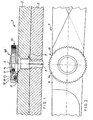
- FIG Shear 1 A first exemplary embodiment is shown in FIG Shear 1 shown, the lower and upper Beck 2, 3rd has which is rotatable by means of an articulated connection 4 are connected.
- the articulated connection 4 has one Hinge pin 5 on the one hand with the lower section 2 in is essentially firmly connected and the other one Head 6, the Oberbeck 3 through a bore 7th rotatably holds together.
- For an articulated lash adjuster 8 is the head 6 with an external thread 9 and a corresponding adjusting nut 10.
- Between the adjusting nut 10 and the Oberbeck 3 is a soft-elastic first arranged centrally to the head 6 Ring 11 arranged.
- the self-locking (relative difficult) adjusting nut 10 is for example formed that the external thread 9 of the head 6 with a Circulation groove 13 is provided in which a soft elastic (Rubber-like) second ring 14 is arranged, the Ring 14 occupies part of the external thread and thereby relative stiffness with the adjusting nut 10 causes.
- This stiffness can be summed up in a big one Frame by an excess of the diameter of the ring 14 in Specify the ratio to the diameter of the external thread 9.
- the binding must be provided be that the adjusting nut 10 when working with the Scissors 1 do not disconnect themselves from the external thread 9 can adjust, but only by manually adjusting the Adjusting nut 10.
- At least one sliding disc 12 for example made of plastic, preferably made of Teflon.
- sliding disks 12, 12 arranged one above the other (not shown) results in an even softer one Cutting feeling with the scissors 1 through a better one Sliding behavior (sliding washer 12 on sliding washer 12 reduces the friction compared to only one sliding disk 12 between ring 11 and a sliding washer 12).
- sliding washer 12 on sliding washer 12 reduces the friction compared to only one sliding disk 12 between ring 11 and a sliding washer 12.
- FIG. 2 A corresponding top view is shown in FIG. 2.
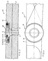
- the second exemplary embodiment according to FIGS. 3 and 4 differs essentially in that the Adjusting nut 15 is sunk into the Oberbeck 3. Thereby becomes, for example, a hooking of hair with the otherwise adjusting nut 10 protruding from Oberbeck 3 prevented.
- the countersunk adjusting nut 10 can be well grip when the diameter of the adjusting nut 10 is equal or is greater than the width of the upper pelvis 3.
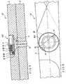
- FIGS. 5 and 6 A third exemplary embodiment is shown in FIGS. 5 and 6 shown.
- the difference to the second Embodiment according to Figures 3 and 4 consists in that instead of the circulation groove 13 with the second ring 14 that External thread 9 is provided with at least one transverse bore 18 in which a preferably elastic plastic pin 19 is arranged, the ends of the pin 19 being a part of the external thread 9.
- a preferably elastic plastic pin 19 is arranged, the ends of the pin 19 being a part of the external thread 9.
- the ends of the pin 19 being a part of the external thread 9.
- Depending on the oversize of the ends and choice of material of the pin 19 can be a desired Specify stiffness. This can result in a lower Construction height can be realized because, in contrast, the usable External thread height is not restricted.
Landscapes
- Life Sciences & Earth Sciences (AREA)
- Forests & Forestry (AREA)
- Engineering & Computer Science (AREA)
- Mechanical Engineering (AREA)
- Scissors And Nippers (AREA)
- Valve-Gear Or Valve Arrangements (AREA)
Abstract
Description
Die Erfindung betrifft eine Schere nach der Gattung des Oberbegriffs des Anspruchs 1.The invention relates to a pair of scissors Preamble of claim 1.
Eine derartige Schere ist aus der die Gattung bildende DE 295 18 029 U1 bekannt . Dadurch, daß eine Einstellmutter verdrehfest mit einem Oberbeck verbunden ist, ändert sich je nach Öffnungswinkel der Becks das Gelenkspiel, wodurch sich die Schneideigenschaft periodisch ändert und damit auch das Schneidgefühl verändert.Such scissors are from the DE forming the genus 295 18 029 U1 known , The fact that an adjusting nut connected torsionally with an Oberbeck changes depending on the opening angle of the Beck the articulation, whereby the cutting property changes periodically and with it the cutting feeling also changed.
Es ist daher Aufgabe der Erfindung, eine gattungsgleiche Schere zu schaffen, die durch einfachste Maßnahmen die obigen Nachteile verhindert.It is therefore an object of the invention to provide a generic one To create scissors by the simplest measures Prevents the above disadvantages.
Gelöst wird diese Aufgabe gemäß Anspruch 1.This task is solved according to Claim 1.
Nach den Merkmalen des Hauptanspruchs wird bei jedem Öffnungswinkel der Becks ein gleichmäßiges Gelenkspiel mit guten Schneideigenschaften und einem individuell weich einstellbaren Schneidgefühl erreicht.According to the features of the main claim, each Opening angle of the Beck with an even joint play good cutting properties and an individually soft adjustable cutting feel achieved.
In einer Weiterbildung der Erfindung ist zwecks Optimierung eines weichen Schneidgefühls vorgesehen, zwischen dem Ring und dem Oberbeck mindestens eine Gleitscheibe aus Kunststoff - vorzugsweise aus Teflon - anzuordnen (Anspruch 2 bis 3).In a development of the invention is for the purpose of optimization a soft cutting feel is provided between the ring and the Oberbeck at least one sliding washer Plastic - preferably made of Teflon - to arrange (claim 2 to 3).
Eine weitere Optimierung wird dadurch erreicht, daß zwei übereinander angeordnete Gleitscheiben vorgesehen sind (Anspruch 4).A further optimization is achieved in that two sliding disks arranged one above the other are provided (Claim 4).
Als vorteilhafte Ausgestaltung einer entsprechend selbsthemmenden Einstellmutter ist vorgesehen, daß das Außengewinde des Kopfs mit einer Umlaufnut versehen ist, in der ein weichelastischer zweiter Ring angeordnet ist, der einen Teil des Außengewindes einnimmt (Anspruch 5).As an advantageous embodiment of a self-locking adjusting nut is provided that the External thread of the head is provided with a circumferential groove, in a soft elastic second ring is arranged, the occupies part of the external thread (claim 5).
In einer bevorzugten Ausgestaltung einer entsprechend selbsthemmenden Einstellmutter ist vorgesehen, daß das Außengewinde des Kopfs quer zur Längsachse mit einer Bohrung versehen ist, in der ein vorzugsweise elastischer Kunststoffstift angeordnet ist, wobei die Enden des Stiftes einen Teil des Außengewindes einnehmen. Dadurch kann ein kürzeres Außengewinde vorgesehen werden, womit durch eine flachere Einstellmutter eine sehr geringe Bauhöhe der Schere realisiert werden kann (Anspruch 6).In a preferred embodiment, a corresponding self-locking adjusting nut is provided that the External thread of the head transverse to the longitudinal axis with a Bore is provided, in which a preferably elastic Plastic pin is arranged, the ends of the pin take up part of the external thread. This can be a shorter external thread can be provided, with a flatter adjusting nut a very low profile Scissors can be realized (claim 6).
Zum manuellen Verstellen der Einstellmutter ist diese mit einer Rändelung versehen (Anspruch 7).For manual adjustment of the adjusting nut, this is included provide knurling (claim 7).
Die Einstellmutter kann aber auch mittels eines Werkzeugs über eine Werkzeugaufnahmeeinrichtung verstellbar ausgebildet sein (Anspruch 8). The adjusting nut can also be used with a tool adjustable via a tool holder be formed (claim 8).
Dadurch, daß die Einstellmutter in das Oberbeck versenkt angeordnet ist, stört diese nicht beim Arbeiten mit der Schere (Anspruch 9).The fact that the adjusting nut sunk into the Oberbeck is arranged, it does not interfere with working with the Scissors (claim 9).
Trotz einer eingesenkten Stellmutter in das Oberbeck läßt sich diese manuell verstellen, wenn der Durchmesser der Einstellmutter ungefähr die Breite des Oberbecks aufweist (Anspruch 10).Despite a countersunk adjusting nut in the Oberbeck leaves adjust them manually if the diameter of the Adjusting nut has approximately the width of the upper pelvis (Claim 10).
Die Erfindung wird anhand von drei Ausführungsbeispielen näher beschrieben.The invention is based on three exemplary embodiments described in more detail.
Es zeigt:
- Figur 1
- in einer geschnittenen Seitenansicht einen Bereich einer Gelenkverbindung eines ersten Ausführungsbeispiels;
- Figur 2
- eine entsprechende Draufsicht nach der Figur 1;
Figur 3- in einer geschnittenen Seitenansicht einen Bereich einer Gelenkverbindung eines zweiten Ausführungsbeispiels;
- Figur 4
- eine entsprechende Draufsicht nach der
Figur 3; Figur 5- in einer geschnittenen Seitenansicht einen Bereich einer Gelenkverbindung eines dritten Ausführungsbeispiels; und
Figur 6- eine entsprechende Draufsicht nach der
Figur 5.
- Figure 1
- in a sectional side view a portion of a hinge connection of a first embodiment;
- Figure 2
- a corresponding plan view of Figure 1;
- Figure 3
- in a sectional side view a portion of a hinge connection of a second embodiment;
- Figure 4
- a corresponding plan view of Figure 3;
- Figure 5
- a section of a side view of a joint connection of a third embodiment; and
- Figure 6
- a corresponding top view of Figure 5.
In der Figur 1 ist ein erstes Ausführungsbeispiel einer
Schere 1 dargestellt, die ein Unter- und Oberbeck 2, 3
aufweist, die mittels einer Gelenkverbindung 4 drehbar
verbunden sind. Die Gelenkverbindung 4 weist einen
Gelenkstift 5 auf, der einerseits mit dem Unterbeck 2 im
wesentlichen fest verbunden ist und der andererseits einen
Kopf 6 aufweist, der das Oberbeck 3 über eine Bohrung 7
drehbar zusammenhält. Für eine Gelenkspieleinstelleinrichtung
8 ist der Kopf 6 mit einem Außengewinde 9 und
einer dazu korrespondierenden Einstellmutter 10 versehen.
Zwischen der Einstellmutter 10 und dem Oberbeck 3 ist ein
weichelastischer, zentrisch zum Kopf 6 angeordneter erster
Ring 11 angeordnet. Die selbsthemmende (relativ
schwergängige) Einstellmutter 10 ist beispielsweise dadurch
gebildet, daß das Außengewinde 9 des Kopfs 6 mit einer
Umlaufnut 13 versehen ist, in der ein weichelastischer
(gummiartiger) zweiter Ring 14 angeordnet ist, wobei der
Ring 14 einen Teil des Außengewindes einnimmt und dadurch
eine relative Schwergängigkeit mit der Einstellmutter 10
bewirkt. Diese Schwergängigkeit läßt sich in einem großen
Rahmen durch ein Übermaß des Durchmessers des Ringes 14 im
Verhältnis zum Durchmesser des Außengewindes 9 vorgeben.
Auf jeden Fall muß die Schwergängigkeit so vorgesehen
werden, daß die Einstellmutter 10 beim Arbeiten mit der
Schere 1 sich nicht selbsttätig vom Außengewinde 9
verstellen kann, sondern nur durch manuelles Verstellen der
Einstellmutter 10. Zwischen dem ersten Ring 11 und dem
Oberbeck 3 ist mindestens eine Gleitscheibe 12 angeordnet,
beispielsweise aus Kunststoff, vorzugsweise aus Teflon.
Durch zwei übereinander angeordnete Gleitscheiben 12, 12
(nicht dargestellt) ergibt sich ein noch weicheres
Schneidgefühl mit der Schere 1 durch ein besseres
Gleitverhalten (Gleitscheibe 12 auf Gleitscheibe 12
reduziert die Reibung gegenüber nur einer Gleitscheibe 12
zwischen Ring 11 und der einen Gleitscheibe 12). Zwecks
besserer Griffigkeit ist die Einstellmutter 10 mit einer
Rändelung 15 versehen.A first exemplary embodiment is shown in FIG
Shear 1 shown, the lower and upper Beck 2, 3rd
has which is rotatable by means of an articulated connection 4
are connected. The articulated connection 4 has one
Hinge
Eine entsprechende Draufsicht geht aus der Figur 2 hervor.A corresponding top view is shown in FIG. 2.
Das zweite Ausführungsbeispiel nach den Figuren 3 und 4
unterscheidet sich im wesentlichen dadurch, daß die
Einstellmutter 15 in das Oberbeck 3 eingesenkt ist. Dadurch
wird ein Verhaken von zum Beispiel Haar mit der ansonsten
aus dem Oberbeck 3 herausstehenden Einstellmutter 10
verhindert. Die eingesenkte Einstellmutter 10 läßt sich gut
greifen, wenn der Durchmesser der Einstellmutter 10 gleich
oder größer ist als die Breite des Oberbecks 3.The second exemplary embodiment according to FIGS. 3 and 4
differs essentially in that the
Ein drittes Ausführungsbeispiel ist in den Figuren 5 und 6
dargestellt. Der Unterschied zu dem zweiten
Ausführungsbeispiel nach den Figuren 3 und 4 besteht darin,
daß anstelle der Umlaufnut 13 mit dem zweiten Ring 14 das
Außengewinde 9 mit mindestens einer Querbohrung 18 versehen
ist, in der ein vorzugsweise elastischer Kunststoffstift 19
angeordnet ist, wobei die Enden des Stiftes 19 einen Teil
des Außengewindes 9 einnehmen. Je nach Übermaß der Enden
und Materialwahl des Stiftes 19 läßt sich eine gewünschte
Schwergängigkeit vorgeben. Dadurch kann eine geringere
Bauhöhe realisiert werden, weil demgegenüber die nutzbare
Außengewindehöhe nicht eingeschränkt ist. Außerdem ist die
Einstellmutter 10.1 mit einer Werkzeugaufnahmeeinrichtung
16 (Bohrungen 17, 17) versehen und wahlweise in das
Oberbeck 3 eingesenkt, wodurch die Einstellmutter 10.1 nur
mit einem Werkzeug verstellt werden kann, was aber den
Vorteil aufweist, daß durch die relativ kleine
Einstellmutter 10.1 eine Verhakungsgefahr von zum Beispiel
Haar noch weiter reduziert ist, da die Einstellmutter 10.1
nicht über die Breite des Oberbecks 3 hinausgeht. A third exemplary embodiment is shown in FIGS. 5 and 6
shown. The difference to the second
Embodiment according to Figures 3 and 4 consists in
that instead of the
- 1, 1.1, 1.21, 1.1, 1.2
- Scherescissors
- 22
- Erste ScherenhälfteFirst half of the scissors
- 33
- Zweite ScherenhälfteSecond half of the scissors
- 44
- Gelenkverbindungarticulation
- 55
- Gelenkstiftpintle
- 66
- Kopfhead
- 77
- Bohrungdrilling
- 8, 8.18, 8.1
- GelenkspieleinstelleinrichtungGelenkspieleinstelleinrichtung
- 99
- Außengewindeexternal thread
- 10, 10.110, 10.1
- Einstellmutteradjusting
- 1111
- Erster RingFirst ring
- 1212
- Gleitscheibesliding disk
- 1313
- Umlaufnutcircumferential groove
- 1414
- Zweiter RingSecond ring
- 1515
- Rändelungknurling
- 1616
- WerkzeugaufnahmeeinrichtungChuck means
- 1717
- Bohrungdrilling
- 1818
- Querbohrungcross hole
- 1919
- KunststoffstiftPlastic pen
Claims (10)
- Scissors with a joint-play-adjusting device (8, 8.1), in particular hair-cutting scissors (1, 1.1), with a bottom arm (2) and top arm (3) which are connected in a rotatable manner by means of a joint connection (4), it being the case that the joint connection (4) has a joint pin (5) which, on the one hand, is essentially fixed to the bottom arm (2) by means of a screw connection, that the joint pin (5), on the other hand, has a head (6) which is provided with an external thread (9) and a corresponding adjusting nut (10, 10.1), and that the joint pin (5) holds the top arm (3) together in a rotatable manner via a bore (7), and that arranged between the adjusting nut (10, 10.1) and the top arm (3) is a first, flexurally elastic ring (11) which is arranged centrally in relation to the head (6) and holds the top arm (3) together in a rotatable manner, characterized in that the adjusting nut (10, 10.1), with the external thread (9), is designed in a self-locking manner, and in that at least one sliding disc (12) is arranged between the first ring (11) and the top arm (3).
- Scissors according to Claim 1, characterized in that the sliding disc (12) consists of plastics material.
- Scissors according to Claim 1, characterized in that the sliding disc (12) consists of Teflon.
- Scissors according at least to Claim 1, characterized in that two sliding discs (12, 12) arranged one above the other are provided.
- Scissors according to Claim 1, characterized in that the external thread (9) of the head (6) is provided with an encircling groove (13) in which a second, flexurally elastic ring (14) is arranged, the ring (14) taking up part of the external thread (9).
- Scissors according to Claim 1, characterized in that the external thread (9) of the head (6) is provided, transversely to the longitudinal axis, with at least one bore (18) in which a preferably elastic plastics-material pin (19) is arranged, the ends of the pin (19) taking up part of the external thread (9).
- Scissors according to Claim 1, characterized in that the adjusting nut (10) is provided with knurling (15).
- Scissors according to Claim 1, characterized in that the adjusting nut (10.1) is provided with a tool-accommodating device (16).
- Scissors according at least to Claim 1, characterized in that the adjusting nut (10, 10.1) is recessed into the top arm (3).
- Scissors according at least to Claim 9, characterized in that the diameter of the adjusting nut (10) corresponds approximately to the width of the top arm (3).
Applications Claiming Priority (4)
| Application Number | Priority Date | Filing Date | Title |
|---|---|---|---|
| DE19742272 | 1997-09-25 | ||
| DE19742272 | 1997-09-25 | ||
| DE19745066 | 1997-10-11 | ||
| DE19745066 | 1997-10-11 |
Publications (2)
| Publication Number | Publication Date |
|---|---|
| EP0904902A1 EP0904902A1 (en) | 1999-03-31 |
| EP0904902B1 true EP0904902B1 (en) | 2003-05-02 |
Family
ID=26040293
Family Applications (1)
| Application Number | Title | Priority Date | Filing Date |
|---|---|---|---|
| EP98117216A Expired - Lifetime EP0904902B1 (en) | 1997-09-25 | 1998-09-11 | Scissors with pivot adjustment mechanism |
Country Status (3)
| Country | Link |
|---|---|
| EP (1) | EP0904902B1 (en) |
| AT (1) | ATE238889T1 (en) |
| DE (2) | DE19841634A1 (en) |
Families Citing this family (1)
| Publication number | Priority date | Publication date | Assignee | Title |
|---|---|---|---|---|
| DE29910126U1 (en) * | 1999-06-10 | 1999-09-09 | >>Dovo<< Stahlwaren Bracht GmbH & Co KG, 42719 Solingen | Scissors with a gear disc |
Family Cites Families (2)
| Publication number | Priority date | Publication date | Assignee | Title |
|---|---|---|---|---|
| DE4117396C1 (en) * | 1991-05-28 | 1992-04-23 | "Jaguar" Stahlwarenfabrik Gmbh & Co Kg, 5650 Solingen, De | |
| DE29518029U1 (en) | 1995-11-14 | 1996-01-04 | Tondeo-Werk GmbH, 42699 Solingen | Hand scissors |
-
1998
- 1998-09-11 EP EP98117216A patent/EP0904902B1/en not_active Expired - Lifetime
- 1998-09-11 AT AT98117216T patent/ATE238889T1/en not_active IP Right Cessation
- 1998-09-11 DE DE19841634A patent/DE19841634A1/en not_active Withdrawn
- 1998-09-11 DE DE59808140T patent/DE59808140D1/en not_active Expired - Lifetime
Also Published As
| Publication number | Publication date |
|---|---|
| EP0904902A1 (en) | 1999-03-31 |
| DE59808140D1 (en) | 2003-06-05 |
| DE19841634A1 (en) | 1999-04-01 |
| ATE238889T1 (en) | 2003-05-15 |
Similar Documents
| Publication | Publication Date | Title |
|---|---|---|
| DE3727706C2 (en) | ||
| DE69400290T2 (en) | Elastic lock for hand tools | |
| DE602005003927T2 (en) | GOVERNOR AND METHOD FOR ADJUSTING TWO PARTS OF A JOINT OF A GEARBOX MEMBER WITH EACH OTHER | |
| DE29609541U1 (en) | Punching device | |
| EP0639431A1 (en) | Support assembly | |
| EP0516598B1 (en) | Pliers with selective front and side introduction | |
| EP0515830B1 (en) | Scissors | |
| DE19739930B4 (en) | Hinge construction and components used in the process | |
| DE20114319U1 (en) | adjustment mechanism | |
| DE2838662A1 (en) | OUTER TENSIONER TO CALM BONE BREAKS | |
| DE3412139A1 (en) | ACTUATION MECHANISM | |
| EP1726403B1 (en) | Lever with height adjustable stop | |
| EP0223186B1 (en) | Adjustable door or window hinge | |
| DE29920171U1 (en) | Pliers with at least two joint settings | |
| DE3786568T2 (en) | Hinge device, in particular for glasses. | |
| EP0904902B1 (en) | Scissors with pivot adjustment mechanism | |
| DE3853364T2 (en) | HINGE STRAPS. | |
| DE29710184U1 (en) | Adjustable bike brake | |
| DE1553846B2 (en) | SCISSOR-LIKE HAND TOOL | |
| EP0191887B1 (en) | Nose-engaging support for spectacles | |
| DE60209543T2 (en) | DEVICE COMPOSED OF A SUPPORT DEVICE AND LOCKING DEVICE PLUS A WINDOW EQUIPMENT WITH SUCH A DEVICE | |
| DE20320931U1 (en) | Pivoting link for mounting card terminal housing on upright has bush on cross pin to transfer clamping compressive forces to large upright tube | |
| DE3029910A1 (en) | HAND SCISSORS WITH AN ADJUSTABLE BEARING CONSTRUCTION | |
| EP0899601B1 (en) | Ophthalmic lens-mounting support | |
| EP1223275B1 (en) | Hinge for doors or windows |
Legal Events
| Date | Code | Title | Description |
|---|---|---|---|
| PUAI | Public reference made under article 153(3) epc to a published international application that has entered the european phase |
Free format text: ORIGINAL CODE: 0009012 |
|
| 17P | Request for examination filed |
Effective date: 19980911 |
|
| AK | Designated contracting states |
Kind code of ref document: A1 Designated state(s): AT CH DE ES FR GB IT LI SE |
|
| AX | Request for extension of the european patent |
Free format text: AL;LT;LV;MK;RO;SI |
|
| AKX | Designation fees paid |
Free format text: AT CH DE ES FR GB IT LI SE |
|
| 17Q | First examination report despatched |
Effective date: 20020111 |
|
| GRAH | Despatch of communication of intention to grant a patent |
Free format text: ORIGINAL CODE: EPIDOS IGRA |
|
| GRAH | Despatch of communication of intention to grant a patent |
Free format text: ORIGINAL CODE: EPIDOS IGRA |
|
| GRAA | (expected) grant |
Free format text: ORIGINAL CODE: 0009210 |
|
| AK | Designated contracting states |
Designated state(s): AT CH DE ES FR GB IT LI SE |
|
| PG25 | Lapsed in a contracting state [announced via postgrant information from national office to epo] |
Ref country code: IT Free format text: LAPSE BECAUSE OF FAILURE TO SUBMIT A TRANSLATION OF THE DESCRIPTION OR TO PAY THE FEE WITHIN THE PRESCRIBED TIME-LIMIT;WARNING: LAPSES OF ITALIAN PATENTS WITH EFFECTIVE DATE BEFORE 2007 MAY HAVE OCCURRED AT ANY TIME BEFORE 2007. THE CORRECT EFFECTIVE DATE MAY BE DIFFERENT FROM THE ONE RECORDED. Effective date: 20030502 Ref country code: GB Free format text: LAPSE BECAUSE OF FAILURE TO SUBMIT A TRANSLATION OF THE DESCRIPTION OR TO PAY THE FEE WITHIN THE PRESCRIBED TIME-LIMIT Effective date: 20030502 Ref country code: FR Free format text: LAPSE BECAUSE OF FAILURE TO SUBMIT A TRANSLATION OF THE DESCRIPTION OR TO PAY THE FEE WITHIN THE PRESCRIBED TIME-LIMIT Effective date: 20030502 |
|
| REG | Reference to a national code |
Ref country code: GB Ref legal event code: FG4D Free format text: NOT ENGLISH |
|
| REG | Reference to a national code |
Ref country code: CH Ref legal event code: EP |
|
| REF | Corresponds to: |
Ref document number: 59808140 Country of ref document: DE Date of ref document: 20030605 Kind code of ref document: P |
|
| PG25 | Lapsed in a contracting state [announced via postgrant information from national office to epo] |
Ref country code: SE Free format text: LAPSE BECAUSE OF FAILURE TO SUBMIT A TRANSLATION OF THE DESCRIPTION OR TO PAY THE FEE WITHIN THE PRESCRIBED TIME-LIMIT Effective date: 20030802 |
|
| PG25 | Lapsed in a contracting state [announced via postgrant information from national office to epo] |
Ref country code: ES Free format text: LAPSE BECAUSE OF FAILURE TO SUBMIT A TRANSLATION OF THE DESCRIPTION OR TO PAY THE FEE WITHIN THE PRESCRIBED TIME-LIMIT Effective date: 20030813 |
|
| PG25 | Lapsed in a contracting state [announced via postgrant information from national office to epo] |
Ref country code: AT Free format text: LAPSE BECAUSE OF NON-PAYMENT OF DUE FEES Effective date: 20030911 |
|
| PG25 | Lapsed in a contracting state [announced via postgrant information from national office to epo] |
Ref country code: LI Free format text: LAPSE BECAUSE OF NON-PAYMENT OF DUE FEES Effective date: 20030930 Ref country code: CH Free format text: LAPSE BECAUSE OF NON-PAYMENT OF DUE FEES Effective date: 20030930 |
|
| GBV | Gb: ep patent (uk) treated as always having been void in accordance with gb section 77(7)/1977 [no translation filed] |
Effective date: 20030502 |
|
| PLBE | No opposition filed within time limit |
Free format text: ORIGINAL CODE: 0009261 |
|
| STAA | Information on the status of an ep patent application or granted ep patent |
Free format text: STATUS: NO OPPOSITION FILED WITHIN TIME LIMIT |
|
| 26N | No opposition filed |
Effective date: 20040203 |
|
| EN | Fr: translation not filed | ||
| REG | Reference to a national code |
Ref country code: CH Ref legal event code: PL |
|
| PGFP | Annual fee paid to national office [announced via postgrant information from national office to epo] |
Ref country code: DE Payment date: 20110907 Year of fee payment: 14 |
|
| REG | Reference to a national code |
Ref country code: DE Ref legal event code: R119 Ref document number: 59808140 Country of ref document: DE Effective date: 20130403 |
|
| PG25 | Lapsed in a contracting state [announced via postgrant information from national office to epo] |
Ref country code: DE Free format text: LAPSE BECAUSE OF NON-PAYMENT OF DUE FEES Effective date: 20130403 |