EP0904884B1 - Welding - Google Patents
Welding Download PDFInfo
- Publication number
- EP0904884B1 EP0904884B1 EP98304450A EP98304450A EP0904884B1 EP 0904884 B1 EP0904884 B1 EP 0904884B1 EP 98304450 A EP98304450 A EP 98304450A EP 98304450 A EP98304450 A EP 98304450A EP 0904884 B1 EP0904884 B1 EP 0904884B1
- Authority
- EP
- European Patent Office
- Prior art keywords
- vessel
- heating element
- welding
- heating
- metallic
- Prior art date
- Legal status (The legal status is an assumption and is not a legal conclusion. Google has not performed a legal analysis and makes no representation as to the accuracy of the status listed.)
- Expired - Lifetime
Links
Images
Classifications
-
- A—HUMAN NECESSITIES
- A47—FURNITURE; DOMESTIC ARTICLES OR APPLIANCES; COFFEE MILLS; SPICE MILLS; SUCTION CLEANERS IN GENERAL
- A47J—KITCHEN EQUIPMENT; COFFEE MILLS; SPICE MILLS; APPARATUS FOR MAKING BEVERAGES
- A47J27/00—Cooking-vessels
- A47J27/004—Cooking-vessels with integral electrical heating means
-
- B—PERFORMING OPERATIONS; TRANSPORTING
- B23—MACHINE TOOLS; METAL-WORKING NOT OTHERWISE PROVIDED FOR
- B23K—SOLDERING OR UNSOLDERING; WELDING; CLADDING OR PLATING BY SOLDERING OR WELDING; CUTTING BY APPLYING HEAT LOCALLY, e.g. FLAME CUTTING; WORKING BY LASER BEAM
- B23K11/00—Resistance welding; Severing by resistance heating
- B23K11/34—Preliminary treatment
-
- B—PERFORMING OPERATIONS; TRANSPORTING
- B23—MACHINE TOOLS; METAL-WORKING NOT OTHERWISE PROVIDED FOR
- B23K—SOLDERING OR UNSOLDERING; WELDING; CLADDING OR PLATING BY SOLDERING OR WELDING; CUTTING BY APPLYING HEAT LOCALLY, e.g. FLAME CUTTING; WORKING BY LASER BEAM
- B23K13/00—Welding by high-frequency current heating
- B23K13/01—Welding by high-frequency current heating by induction heating
-
- B—PERFORMING OPERATIONS; TRANSPORTING
- B23—MACHINE TOOLS; METAL-WORKING NOT OTHERWISE PROVIDED FOR
- B23K—SOLDERING OR UNSOLDERING; WELDING; CLADDING OR PLATING BY SOLDERING OR WELDING; CUTTING BY APPLYING HEAT LOCALLY, e.g. FLAME CUTTING; WORKING BY LASER BEAM
- B23K13/00—Welding by high-frequency current heating
- B23K13/06—Welding by high-frequency current heating characterised by the shielding of the welding zone against influence of the surrounding atmosphere
-
- B—PERFORMING OPERATIONS; TRANSPORTING
- B23—MACHINE TOOLS; METAL-WORKING NOT OTHERWISE PROVIDED FOR
- B23K—SOLDERING OR UNSOLDERING; WELDING; CLADDING OR PLATING BY SOLDERING OR WELDING; CUTTING BY APPLYING HEAT LOCALLY, e.g. FLAME CUTTING; WORKING BY LASER BEAM
- B23K13/00—Welding by high-frequency current heating
- B23K13/08—Electric supply or control circuits therefor
-
- Y—GENERAL TAGGING OF NEW TECHNOLOGICAL DEVELOPMENTS; GENERAL TAGGING OF CROSS-SECTIONAL TECHNOLOGIES SPANNING OVER SEVERAL SECTIONS OF THE IPC; TECHNICAL SUBJECTS COVERED BY FORMER USPC CROSS-REFERENCE ART COLLECTIONS [XRACs] AND DIGESTS
- Y10—TECHNICAL SUBJECTS COVERED BY FORMER USPC
- Y10T—TECHNICAL SUBJECTS COVERED BY FORMER US CLASSIFICATION
- Y10T29/00—Metal working
- Y10T29/49—Method of mechanical manufacture
- Y10T29/49002—Electrical device making
- Y10T29/49082—Resistor making
- Y10T29/49083—Heater type
Definitions
- the invention relates to welding where components are joined together by heating component together to cause contacting surfaces to fuse and form a joint to hold the components together thereafter during normal use.
- Many vessels are used especially, but not exclusively, in domestic appliances to heat liquids, usually water, using an electric heating element.
- the heating element is attached directly to an outside surface of the vessel by some kind of welding process. In this way the heating element is conveniently supported by the vessel and provides a good conducting path for heat to enter the walls of the vessel.
- the vessels are made of metal and the electric element is insulated within a metal case or shield. It is already known to connect and fix the electric element to directly an outside surface of vessels by methods of hot welding. However, such methods are usually carried out in shrouded environments or furnaces so that each vessel, in a batch of vessels say, can be raised to the required temperatures, and held in contact with a respective electric heating element in the presence of a welding flux. Such methods are time consuming and must take place in a very carefully temperature controlled environment to avoid over-heating and possible permanent damage to either or both components.
- a method of heat welding a metallic sheathed heating element to a metal vessel comprising heating the vessel by an induction heater, or similar, to a temperature around the welding point, firmly holding the heating element against a surface of the vessel and applying for a suitable time an electric current to the heating element to raise the temperature of metallic sheath and the contacted surface of the vessel to the welding temperatures to cause the contacting surfaces to fuse and weld together.
- the method may comprise heating the inside of the vessel and welding the heating element to an outside surface of the vessel.
- the heating element may be in the form of a circular flat coil.
- the coil may have two or more turns.
- a generally conventional electric heating element has a central conductor 10 surrounded by insulating material contained within an outer metallic sheath 11.
- a metallic vessel 12 has a base 13 which may be somewhat thicker than side walls of the vessel and/or provided with a bonded base plate if preferred. The heating element is welded to the base as shown.
- the vessel is heated by an induction heater 14, or similar, mounted inside the vessel but not necessarily in contact with the base of the vessel.
- the electric heating element is held in firm contact against the base of the vessel and electric power applied to the conductor 10 to heat the sheath 11, as well as the vessel surface that is in contact with the sheath, to cause the metals to melt and fuse as required to form a welded joint between them.
- a suitable flux is pre-applied to the joining surfaces to assist the fusion and to inhibit metallic oxidation during the welding operation.
- the vessel is heated in practice to around 550°C by the heater 14 and a voltage of around 35 volts is supplied to the heating element 10 for about 2 minutes.
- the power supplied to the heating element raises the temperatures at the contacting welding surfaces of the sheath and the base of the vessel to, say, 570°C which allows and causes those contacting surfaces to fuse and so become welded together when the power supply is cutoff and the contacting surfaces cool down.
- the heating element may be a coil shape as shown in Figure 2 but may, where preferred, comprise a coil with two or more turns.
- the base of the vessel may be formed without a bonded or "thickened" base plate mentioned above, which in the prior art is provided to spread heat out across the base 13 in use.
- the heating element may be attached to a top outer peripheral surface of a vessel 12, such as for use in a single loaf breadmaker. Indeed and generally, the relative position of joining the heating element to the vessel is not limited for embodiments of the invention; and if required, the heating element can be welded to an inside surface of the vessel.
Landscapes
- Engineering & Computer Science (AREA)
- Mechanical Engineering (AREA)
- Food Science & Technology (AREA)
- Cookers (AREA)
- Lining Or Joining Of Plastics Or The Like (AREA)
Description
- The invention relates to welding where components are joined together by heating component together to cause contacting surfaces to fuse and form a joint to hold the components together thereafter during normal use.
- Many vessels are used especially, but not exclusively, in domestic appliances to heat liquids, usually water, using an electric heating element. Conveniently for many applications, the heating element is attached directly to an outside surface of the vessel by some kind of welding process. In this way the heating element is conveniently supported by the vessel and provides a good conducting path for heat to enter the walls of the vessel. The vessels are made of metal and the electric element is insulated within a metal case or shield. It is already known to connect and fix the electric element to directly an outside surface of vessels by methods of hot welding. However, such methods are usually carried out in shrouded environments or furnaces so that each vessel, in a batch of vessels say, can be raised to the required temperatures, and held in contact with a respective electric heating element in the presence of a welding flux. Such methods are time consuming and must take place in a very carefully temperature controlled environment to avoid over-heating and possible permanent damage to either or both components.
- DE-A-34 34 485, which is considered to represent the most relevant state of the art, discloses a five-phase process for manufacturing a saucepan. In this specification, inductive heating is described as a means of heating the base plates prior to pressing them together to form the base of the saucepan. This specification does not, however, disclose any method of attaching a heating element permanently to a metal vessel.
- DE-A-25 59 232 and US-A-4 052 590 describe sheathed electric heater elements connected to metal vessels.
- It is an object of the invention to simplify the welding method to enable the welding to take place in particular on a generally open production line, if preferred.
- According to the invention there is provided a method of heat welding a metallic sheathed heating element to a metal vessel, comprising heating the vessel by an induction heater, or similar, to a temperature around the welding point, firmly holding the heating element against a surface of the vessel and applying for a suitable time an electric current to the heating element to raise the temperature of metallic sheath and the contacted surface of the vessel to the welding temperatures to cause the contacting surfaces to fuse and weld together.
- The method may comprise heating the inside of the vessel and welding the heating element to an outside surface of the vessel.
- The heating element may be in the form of a circular flat coil. The coil may have two or more turns.
- A method of welding an electric heating element to a metallic vessel according to the invention will now be described by way of example with reference to the accompanying drawings in which :-
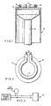
- Figure 1 shows a cross-sectional side view of the heating element and the vessel;
- Figure 2 shows an underplan view of the vessel; and
- Figure 3 shows an electrical schematic diagram for supplying electric power to the heating element when carrying out the method.
-
- Referring to the drawings, in Figures 1 and 2, a generally conventional electric heating element has a
central conductor 10 surrounded by insulating material contained within an outermetallic sheath 11. Ametallic vessel 12 has abase 13 which may be somewhat thicker than side walls of the vessel and/or provided with a bonded base plate if preferred. The heating element is welded to the base as shown. - In order to carry out the method, the vessel is heated by an
induction heater 14, or similar, mounted inside the vessel but not necessarily in contact with the base of the vessel. The electric heating element is held in firm contact against the base of the vessel and electric power applied to theconductor 10 to heat thesheath 11, as well as the vessel surface that is in contact with the sheath, to cause the metals to melt and fuse as required to form a welded joint between them. As in normal welding, a suitable flux is pre-applied to the joining surfaces to assist the fusion and to inhibit metallic oxidation during the welding operation. - Typically for an
aluminium sheath 11 and analuminium vessel 12, the vessel is heated in practice to around 550°C by theheater 14 and a voltage of around 35 volts is supplied to theheating element 10 for about 2 minutes. The power supplied to the heating element raises the temperatures at the contacting welding surfaces of the sheath and the base of the vessel to, say, 570°C which allows and causes those contacting surfaces to fuse and so become welded together when the power supply is cutoff and the contacting surfaces cool down. - Where other weldable materials are used somewhat different temperatures and cycle times for the method may be required. However, in all embodiments of the invention, it will be appreciated that generally no heat shrouds or environmental protection, for example a heat insulated confined heating chamber, are necessary. The
vessel 12 will be effectively and efficiently heated without close intimate contacting with theheater 14 and so no precision fitting together is required. Also, the actual heating for creating the weld is directed very specifically at or in the contacting surfaces that are to be welded and the temperatures at such surfaces can be very easily controlled by using a rheostat or similar to control the applied power, in any event by relatively simple control of the electrical current through theconductor 10. - It will be appreciated that the heating element may be a coil shape as shown in Figure 2 but may, where preferred, comprise a coil with two or more turns. As such, the base of the vessel may be formed without a bonded or "thickened" base plate mentioned above, which in the prior art is provided to spread heat out across the
base 13 in use. It will be noted that the heating element may be attached to a top outer peripheral surface of avessel 12, such as for use in a single loaf breadmaker. Indeed and generally, the relative position of joining the heating element to the vessel is not limited for embodiments of the invention; and if required, the heating element can be welded to an inside surface of the vessel.
Claims (4)
- A method of heat welding a metallic sheathed heating element (10, 11) to a metal vessel (12), comprising heating the vessel by an induction heater (14), or similar, to a temperature around the welding point, firmly holding the heating element (10, 11) against a surface of the vessel (12) and applying for a suitable time an electric current to the heating element (10, 11) to raise the temperature of metallic sheath (11) and the contacted surface of the vessel (12) to the welding temperatures to cause the contacting surfaces to fuse and weld together.
- A method according to claim 1, comprising heating the inside of the vessel (12) and welding the heating element (10, 11) to an outside surface of the vessel (12).
- A method according to claim 1 or 2, in which the heating element (10, 11) is in the form of a circular flat coil.
- A method according to claim 3, in which the coil has two or more turns.
Applications Claiming Priority (2)
| Application Number | Priority Date | Filing Date | Title |
|---|---|---|---|
| GB9719159 | 1997-09-09 | ||
| GB9719159A GB2328893B (en) | 1997-09-09 | 1997-09-09 | Welding |
Publications (3)
| Publication Number | Publication Date |
|---|---|
| EP0904884A2 EP0904884A2 (en) | 1999-03-31 |
| EP0904884A3 EP0904884A3 (en) | 1999-11-24 |
| EP0904884B1 true EP0904884B1 (en) | 2003-01-15 |
Family
ID=10818799
Family Applications (1)
| Application Number | Title | Priority Date | Filing Date |
|---|---|---|---|
| EP98304450A Expired - Lifetime EP0904884B1 (en) | 1997-09-09 | 1998-06-05 | Welding |
Country Status (6)
| Country | Link |
|---|---|
| US (1) | US5994680A (en) |
| EP (1) | EP0904884B1 (en) |
| AU (1) | AU734867B2 (en) |
| CA (1) | CA2241061A1 (en) |
| DE (1) | DE69810726T2 (en) |
| GB (1) | GB2328893B (en) |
Families Citing this family (2)
| Publication number | Priority date | Publication date | Assignee | Title |
|---|---|---|---|---|
| GB9808634D0 (en) * | 1998-04-24 | 1998-06-24 | Koninkl Philips Electronics Nv | Heating apparatus and heating element assembly method |
| ES2185444B2 (en) * | 2000-03-14 | 2004-06-01 | Salva Industrial, S.A. | PROCEDURE FOR THE MANUFACTURE OF ELECTRIC BUCKETS FOR PASTRY AND BUCKET OBTAINED WITH THE SAME. |
Family Cites Families (6)
| Publication number | Priority date | Publication date | Assignee | Title |
|---|---|---|---|---|
| US2937261A (en) * | 1955-11-08 | 1960-05-17 | Sunbeam Corp | Electric cooking vessel and method of making same |
| ES436683A1 (en) * | 1975-04-17 | 1977-02-01 | Ismael Martinez Pelegri | Improvements in methods for metal welding. (Machine-translation by Google Translate, not legally binding) |
| DE3301833A1 (en) * | 1983-01-20 | 1984-07-26 | Gesellschaft für Biotechnologische Forschung mbH (GBF), 3300 Braunschweig | METHOD FOR SIMULTANEOUS SYNTHESIS OF SEVERAL OLIGONOCLEOTIDES IN A SOLID PHASE |
| IT1195553B (en) * | 1983-12-02 | 1988-10-19 | S I A T E M Spa Soc Italiana A | FLAT INDUCTORS WITH ITS THERMAL INSULATION FOR DIFFERENTIATED HEATING OF BOTTLES ON STEEL DISHES |
| SE441074B (en) * | 1984-01-24 | 1985-09-09 | Akerlund & Rausing Ab | DEVICE WELDING DEVICE |
| HU192884B (en) * | 1984-05-14 | 1987-07-28 | Pal Gal | Method for cohesive bonding metal pieces by deformation indirect material particularly for members of small material thickness |
-
1997
- 1997-09-09 GB GB9719159A patent/GB2328893B/en not_active Expired - Fee Related
-
1998
- 1998-06-04 AU AU69913/98A patent/AU734867B2/en not_active Ceased
- 1998-06-05 EP EP98304450A patent/EP0904884B1/en not_active Expired - Lifetime
- 1998-06-05 DE DE69810726T patent/DE69810726T2/en not_active Expired - Fee Related
- 1998-06-10 US US09/095,518 patent/US5994680A/en not_active Expired - Fee Related
- 1998-06-18 CA CA002241061A patent/CA2241061A1/en not_active Abandoned
Also Published As
| Publication number | Publication date |
|---|---|
| EP0904884A3 (en) | 1999-11-24 |
| CA2241061A1 (en) | 1999-03-09 |
| AU6991398A (en) | 1999-03-25 |
| DE69810726T2 (en) | 2003-10-16 |
| GB2328893B (en) | 2002-05-01 |
| GB9719159D0 (en) | 1997-11-12 |
| AU734867B2 (en) | 2001-06-21 |
| DE69810726D1 (en) | 2003-02-20 |
| US5994680A (en) | 1999-11-30 |
| EP0904884A2 (en) | 1999-03-31 |
| GB2328893A (en) | 1999-03-10 |
Similar Documents
| Publication | Publication Date | Title |
|---|---|---|
| US5167545A (en) | Connector containing fusible material and having intrinsic temperature control | |
| US5163856A (en) | Multipin connector | |
| EP0241597B1 (en) | Electrical circuit containing fusible material and having intrinsic temperature control | |
| JP3992756B2 (en) | Heating apparatus and method for assembling heating element | |
| US4665309A (en) | Self heating gasket for hermetically sealing a lid to a box | |
| JPH0646526B2 (en) | Self-heating, self-welding bus bar | |
| US5098319A (en) | Multipin connector | |
| US5408579A (en) | Electric element assembly | |
| US4771151A (en) | Self-heating lid for soldering to a box | |
| JP3199178B2 (en) | Self-adjusting coupling device containing fusible material | |
| EP0904884B1 (en) | Welding | |
| US20040238510A1 (en) | Soldering method for metal fastening elements | |
| US7355142B2 (en) | Resistance welding electrode, welded copper flex lead, and method for making same | |
| US11641698B2 (en) | Connecting thermally-sprayed layer structures of heating devices | |
| GB1590836A (en) | Electrically heated apparatus | |
| GB2239827A (en) | Method for joining conductor parts of an electric switch component | |
| JP2000348854A (en) | Electrically heating unit | |
| GB2202169A (en) | Method for joining conductor parts of an electric switch component | |
| JPS6213321A (en) | Method for mutually welding synthetic resin parts by high frequency induction heating method | |
| JPS59117806A (en) | Waveguide-flange bonding method | |
| JPH04264224A (en) | Manufacture of component provided with thermistor | |
| Khomenko | About Some Physical Processes in Ceramics Welding With a Glass in Electrical Field | |
| JPS58103959A (en) | Method for brazing sheathed heater to aluminum vessel |
Legal Events
| Date | Code | Title | Description |
|---|---|---|---|
| PUAI | Public reference made under article 153(3) epc to a published international application that has entered the european phase |
Free format text: ORIGINAL CODE: 0009012 |
|
| AK | Designated contracting states |
Kind code of ref document: A2 Designated state(s): BE DE ES FR GB IE IT NL PT |
|
| AX | Request for extension of the european patent |
Free format text: AL;LT;LV;MK;RO;SI |
|
| PUAL | Search report despatched |
Free format text: ORIGINAL CODE: 0009013 |
|
| AK | Designated contracting states |
Kind code of ref document: A3 Designated state(s): AT BE CH CY DE DK ES FI FR GB GR IE IT LI LU MC NL PT SE |
|
| AX | Request for extension of the european patent |
Free format text: AL;LT;LV;MK;RO;SI |
|
| RIC1 | Information provided on ipc code assigned before grant |
Free format text: 6B 23K 11/00 A, 6B 23K 13/01 B |
|
| 17P | Request for examination filed |
Effective date: 20000523 |
|
| AKX | Designation fees paid |
Free format text: BE DE ES FR GB IE IT NL PT |
|
| AXX | Extension fees paid |
Free format text: AL PAYMENT 20000523;LT PAYMENT 20000523;LV PAYMENT 20000523;MK PAYMENT 20000523;RO PAYMENT 20000523;SI PAYMENT 20000523 |
|
| 17Q | First examination report despatched |
Effective date: 20010920 |
|
| GRAG | Despatch of communication of intention to grant |
Free format text: ORIGINAL CODE: EPIDOS AGRA |
|
| GRAG | Despatch of communication of intention to grant |
Free format text: ORIGINAL CODE: EPIDOS AGRA |
|
| GRAH | Despatch of communication of intention to grant a patent |
Free format text: ORIGINAL CODE: EPIDOS IGRA |
|
| RAP1 | Party data changed (applicant data changed or rights of an application transferred) |
Owner name: CHIAPHUA INDUSTRIES LIMITED |
|
| GRAH | Despatch of communication of intention to grant a patent |
Free format text: ORIGINAL CODE: EPIDOS IGRA |
|
| GRAA | (expected) grant |
Free format text: ORIGINAL CODE: 0009210 |
|
| AK | Designated contracting states |
Kind code of ref document: B1 Designated state(s): BE DE ES FR GB IE IT NL PT |
|
| AX | Request for extension of the european patent |
Free format text: AL PAYMENT 20000523;LT PAYMENT 20000523;LV PAYMENT 20000523;MK PAYMENT 20000523;RO PAYMENT 20000523;SI PAYMENT 20000523 |
|
| PG25 | Lapsed in a contracting state [announced via postgrant information from national office to epo] |
Ref country code: NL Free format text: LAPSE BECAUSE OF FAILURE TO SUBMIT A TRANSLATION OF THE DESCRIPTION OR TO PAY THE FEE WITHIN THE PRESCRIBED TIME-LIMIT Effective date: 20030115 Ref country code: IT Free format text: LAPSE BECAUSE OF FAILURE TO SUBMIT A TRANSLATION OF THE DESCRIPTION OR TO PAY THE FEE WITHIN THE PRE;WARNING: LAPSES OF ITALIAN PATENTS WITH EFFECTIVE DATE BEFORE 2007 MAY HAVE OCCURRED AT ANY TIME BEFORE 2007. THE CORRECT EFFECTIVE DATE MAY BE DIFFERENT FROM THE ONE RECORDED.SCRIBED TIME-LIMIT Effective date: 20030115 Ref country code: BE Free format text: LAPSE BECAUSE OF FAILURE TO SUBMIT A TRANSLATION OF THE DESCRIPTION OR TO PAY THE FEE WITHIN THE PRESCRIBED TIME-LIMIT Effective date: 20030115 |
|
| REG | Reference to a national code |
Ref country code: GB Ref legal event code: FG4D |
|
| REG | Reference to a national code |
Ref country code: IE Ref legal event code: FG4D |
|
| REF | Corresponds to: |
Ref document number: 69810726 Country of ref document: DE Date of ref document: 20030220 Kind code of ref document: P |
|
| PG25 | Lapsed in a contracting state [announced via postgrant information from national office to epo] |
Ref country code: PT Free format text: LAPSE BECAUSE OF FAILURE TO SUBMIT A TRANSLATION OF THE DESCRIPTION OR TO PAY THE FEE WITHIN THE PRESCRIBED TIME-LIMIT Effective date: 20030415 |
|
| PG25 | Lapsed in a contracting state [announced via postgrant information from national office to epo] |
Ref country code: IE Free format text: LAPSE BECAUSE OF NON-PAYMENT OF DUE FEES Effective date: 20030605 Ref country code: GB Free format text: LAPSE BECAUSE OF NON-PAYMENT OF DUE FEES Effective date: 20030605 |
|
| LTIE | Lt: invalidation of european patent or patent extension |
Effective date: 20030115 |
|
| NLV1 | Nl: lapsed or annulled due to failure to fulfill the requirements of art. 29p and 29m of the patents act | ||
| PG25 | Lapsed in a contracting state [announced via postgrant information from national office to epo] |
Ref country code: ES Free format text: LAPSE BECAUSE OF FAILURE TO SUBMIT A TRANSLATION OF THE DESCRIPTION OR TO PAY THE FEE WITHIN THE PRESCRIBED TIME-LIMIT Effective date: 20030730 |
|
| ET | Fr: translation filed | ||
| PLBE | No opposition filed within time limit |
Free format text: ORIGINAL CODE: 0009261 |
|
| STAA | Information on the status of an ep patent application or granted ep patent |
Free format text: STATUS: NO OPPOSITION FILED WITHIN TIME LIMIT |
|
| PG25 | Lapsed in a contracting state [announced via postgrant information from national office to epo] |
Ref country code: DE Free format text: LAPSE BECAUSE OF NON-PAYMENT OF DUE FEES Effective date: 20040101 |
|
| 26N | No opposition filed |
Effective date: 20031016 |
|
| GBPC | Gb: european patent ceased through non-payment of renewal fee |
Effective date: 20030605 |
|
| PG25 | Lapsed in a contracting state [announced via postgrant information from national office to epo] |
Ref country code: FR Free format text: LAPSE BECAUSE OF NON-PAYMENT OF DUE FEES Effective date: 20040227 |
|
| REG | Reference to a national code |
Ref country code: FR Ref legal event code: ST |
|
| REG | Reference to a national code |
Ref country code: IE Ref legal event code: MM4A |