EP0904877A2 - Method and apparatus for cutting continuously supplied material - Google Patents
Method and apparatus for cutting continuously supplied material Download PDFInfo
- Publication number
- EP0904877A2 EP0904877A2 EP97830621A EP97830621A EP0904877A2 EP 0904877 A2 EP0904877 A2 EP 0904877A2 EP 97830621 A EP97830621 A EP 97830621A EP 97830621 A EP97830621 A EP 97830621A EP 0904877 A2 EP0904877 A2 EP 0904877A2
- Authority
- EP
- European Patent Office
- Prior art keywords
- drums
- drum
- shearing device
- cutting
- rotation
- Prior art date
- Legal status (The legal status is an assumption and is not a legal conclusion. Google has not performed a legal analysis and makes no representation as to the accuracy of the status listed.)
- Granted
Links
Images


Classifications
-
- B—PERFORMING OPERATIONS; TRANSPORTING
- B26—HAND CUTTING TOOLS; CUTTING; SEVERING
- B26D—CUTTING; DETAILS COMMON TO MACHINES FOR PERFORATING, PUNCHING, CUTTING-OUT, STAMPING-OUT OR SEVERING
- B26D7/00—Details of apparatus for cutting, cutting-out, stamping-out, punching, perforating, or severing by means other than cutting
- B26D7/26—Means for mounting or adjusting the cutting member; Means for adjusting the stroke of the cutting member
- B26D7/2628—Means for adjusting the position of the cutting member
- B26D7/265—Journals, bearings or supports for positioning rollers or cylinders relatively to each other
-
- B—PERFORMING OPERATIONS; TRANSPORTING
- B23—MACHINE TOOLS; METAL-WORKING NOT OTHERWISE PROVIDED FOR
- B23D—PLANING; SLOTTING; SHEARING; BROACHING; SAWING; FILING; SCRAPING; LIKE OPERATIONS FOR WORKING METAL BY REMOVING MATERIAL, NOT OTHERWISE PROVIDED FOR
- B23D25/00—Machines or arrangements for shearing stock while the latter is travelling otherwise than in the direction of the cut
- B23D25/12—Shearing machines with blades on coacting rotating drums
-
- B—PERFORMING OPERATIONS; TRANSPORTING
- B26—HAND CUTTING TOOLS; CUTTING; SEVERING
- B26D—CUTTING; DETAILS COMMON TO MACHINES FOR PERFORATING, PUNCHING, CUTTING-OUT, STAMPING-OUT OR SEVERING
- B26D1/00—Cutting through work characterised by the nature or movement of the cutting member or particular materials not otherwise provided for; Apparatus or machines therefor; Cutting members therefor
- B26D1/56—Cutting through work characterised by the nature or movement of the cutting member or particular materials not otherwise provided for; Apparatus or machines therefor; Cutting members therefor involving a cutting member which travels with the work otherwise than in the direction of the cut, i.e. flying cutter
- B26D1/62—Cutting through work characterised by the nature or movement of the cutting member or particular materials not otherwise provided for; Apparatus or machines therefor; Cutting members therefor involving a cutting member which travels with the work otherwise than in the direction of the cut, i.e. flying cutter and is rotating about an axis parallel to the line of cut, e.g. mounted on a rotary cylinder
- B26D1/626—Cutting through work characterised by the nature or movement of the cutting member or particular materials not otherwise provided for; Apparatus or machines therefor; Cutting members therefor involving a cutting member which travels with the work otherwise than in the direction of the cut, i.e. flying cutter and is rotating about an axis parallel to the line of cut, e.g. mounted on a rotary cylinder for thin material, e.g. for sheets, strips or the like
-
- B—PERFORMING OPERATIONS; TRANSPORTING
- B26—HAND CUTTING TOOLS; CUTTING; SEVERING
- B26D—CUTTING; DETAILS COMMON TO MACHINES FOR PERFORATING, PUNCHING, CUTTING-OUT, STAMPING-OUT OR SEVERING
- B26D5/00—Arrangements for operating and controlling machines or devices for cutting, cutting-out, stamping-out, punching, perforating, or severing by means other than cutting
- B26D5/02—Means for moving the cutting member into its operative position for cutting
- B26D5/04—Means for moving the cutting member into its operative position for cutting by fluid pressure
-
- B—PERFORMING OPERATIONS; TRANSPORTING
- B26—HAND CUTTING TOOLS; CUTTING; SEVERING
- B26D—CUTTING; DETAILS COMMON TO MACHINES FOR PERFORATING, PUNCHING, CUTTING-OUT, STAMPING-OUT OR SEVERING
- B26D7/00—Details of apparatus for cutting, cutting-out, stamping-out, punching, perforating, or severing by means other than cutting
- B26D7/26—Means for mounting or adjusting the cutting member; Means for adjusting the stroke of the cutting member
- B26D7/2628—Means for adjusting the position of the cutting member
-
- B—PERFORMING OPERATIONS; TRANSPORTING
- B21—MECHANICAL METAL-WORKING WITHOUT ESSENTIALLY REMOVING MATERIAL; PUNCHING METAL
- B21B—ROLLING OF METAL
- B21B15/00—Arrangements for performing additional metal-working operations specially combined with or arranged in, or specially adapted for use in connection with, metal-rolling mills
- B21B15/0007—Cutting or shearing the product
- B21B2015/0014—Cutting or shearing the product transversely to the rolling direction
-
- B—PERFORMING OPERATIONS; TRANSPORTING
- B21—MECHANICAL METAL-WORKING WITHOUT ESSENTIALLY REMOVING MATERIAL; PUNCHING METAL
- B21B—ROLLING OF METAL
- B21B2203/00—Auxiliary arrangements, devices or methods in combination with rolling mills or rolling methods
- B21B2203/22—Hinged chocks
-
- B—PERFORMING OPERATIONS; TRANSPORTING
- B21—MECHANICAL METAL-WORKING WITHOUT ESSENTIALLY REMOVING MATERIAL; PUNCHING METAL
- B21B—ROLLING OF METAL
- B21B31/00—Rolling stand structures; Mounting, adjusting, or interchanging rolls, roll mountings, or stand frames
- B21B31/02—Rolling stand frames or housings; Roll mountings ; Roll chocks
-
- B—PERFORMING OPERATIONS; TRANSPORTING
- B26—HAND CUTTING TOOLS; CUTTING; SEVERING
- B26D—CUTTING; DETAILS COMMON TO MACHINES FOR PERFORATING, PUNCHING, CUTTING-OUT, STAMPING-OUT OR SEVERING
- B26D1/00—Cutting through work characterised by the nature or movement of the cutting member or particular materials not otherwise provided for; Apparatus or machines therefor; Cutting members therefor
- B26D1/56—Cutting through work characterised by the nature or movement of the cutting member or particular materials not otherwise provided for; Apparatus or machines therefor; Cutting members therefor involving a cutting member which travels with the work otherwise than in the direction of the cut, i.e. flying cutter
- B26D1/62—Cutting through work characterised by the nature or movement of the cutting member or particular materials not otherwise provided for; Apparatus or machines therefor; Cutting members therefor involving a cutting member which travels with the work otherwise than in the direction of the cut, i.e. flying cutter and is rotating about an axis parallel to the line of cut, e.g. mounted on a rotary cylinder
- B26D2001/623—Cutting through work characterised by the nature or movement of the cutting member or particular materials not otherwise provided for; Apparatus or machines therefor; Cutting members therefor involving a cutting member which travels with the work otherwise than in the direction of the cut, i.e. flying cutter and is rotating about an axis parallel to the line of cut, e.g. mounted on a rotary cylinder for selecting different knife sets by shifting the angle of the rotary cylinder
-
- B—PERFORMING OPERATIONS; TRANSPORTING
- B26—HAND CUTTING TOOLS; CUTTING; SEVERING
- B26D—CUTTING; DETAILS COMMON TO MACHINES FOR PERFORATING, PUNCHING, CUTTING-OUT, STAMPING-OUT OR SEVERING
- B26D5/00—Arrangements for operating and controlling machines or devices for cutting, cutting-out, stamping-out, punching, perforating, or severing by means other than cutting
- B26D5/08—Means for actuating the cutting member to effect the cut
- B26D5/18—Toggle-link means
-
- B—PERFORMING OPERATIONS; TRANSPORTING
- B26—HAND CUTTING TOOLS; CUTTING; SEVERING
- B26D—CUTTING; DETAILS COMMON TO MACHINES FOR PERFORATING, PUNCHING, CUTTING-OUT, STAMPING-OUT OR SEVERING
- B26D5/00—Arrangements for operating and controlling machines or devices for cutting, cutting-out, stamping-out, punching, perforating, or severing by means other than cutting
- B26D5/20—Arrangements for operating and controlling machines or devices for cutting, cutting-out, stamping-out, punching, perforating, or severing by means other than cutting with interrelated action between the cutting member and work feed
Definitions
- the present invention relates to the cutting of material supplied continuously at high speeds, as occurs, for example, in the iron and steel industry during the production of rolled metal strips with thin thicknesses, i.e. less than 1.5 mm.
- the invention relates to a cutting method according to what has been stated above, wherein a shearing device with rotating drums is used.
- shearing devices are already known and are used in the processing of flat metal rolled products; they consist of two opposed and counter-rotating cylindrical drums, having parallel axes and being spaced from one another so as to leave the necessary space for the passage of a strip moved forwards between the two drums; in this connection it just needs to be pointed out that, for feeding the material to be cut, means known per se generally located either upstream and downstream of the shearing device are provided.
- the cutting edge thereof projects with respect to the remainder of the external surface of the corresponding drum: the cutting action is performed as a result of the meeting together, along the plane containing the axes of rotation of the neighbouring drums, of the respective blades when they find themselves opposed one another.
- the drums are operated by means of a single driving motor with an annexed transmission system, generally called divider, so as to obtain the same angular speed of rotation; the peripheral speeds of the drums are moreover close to the strip feeding speed.
- the problems arise when the strip is supplied continuously, i.e. without interruption, at feed speeds greater than 10 m/s, for example 15-20 m/s, as occurs in the hot production of rolled strips with a thickness less than one millimetre.
- the drums remain mostly in a standstill condition and only at the moment of cutting they are activated for a fraction of a revolution: this occurs so that after cutting has been performed, the blades are brought out of interference following to the rotation of the drums through a sufficient angle; thereafter the drums are stopped and remain in a standby condition for the subsequent cutting.
- Another solution which is adopted in the case of processing at higher speeds, consists in combining rotation of the drums with their displacement between a position close to the material to be cut and a position removed therefrom.
- the drums are started in motion while they are located still far from the strip; only subsequently they are brought into the close position so as to allow the blades to act on the advancing strip.
- the technical problem underlying the present invention is therefore that of remedying this state of things: namely, it consists in devising a method for cutting material which is continuously supplied at high speeds, greater than 10 m/s and for example at about 15-20 m/s, that can be implemented with a shearing device with counter-rotating drums having structural and operational characteristics such as to overcome the drawbacks mentioned above.
- the invention includes, moreover, a shearing device for carrying out the aforesaid method, which is also characterized in the annexed claims.
- the reference 1 generally indicates a shearing device for cutting a rolled metal strip N.
- This device comprises a motor 2 downstream of which a divider mechanism 3 (referred to below briefly as “divider”) is connected; the latter transmits at its output a rotary movement to a pair of shafts 4 and 5 having respectively mounted at their ends an upper drum 6 and a lower drum 7 (the first of which has been shown in cross-section in Figure 1) intended for cutting the strip N advancing along the shearing device.
- a divider mechanism 3 referred to below briefly as “divider”
- the drums 6 and 7 have an external diameter slightly different from one another and in this case the first drum is smaller than the second one.
- the drum 6 consists of a central axle 61 connected to the shaft 4 for its rotation, at the ends of which there are keyed two spacing devices 62 and 63; the latter are formed by a series of struts (see Figures 2 and 3) diametrically opposed with respect to the hub on which they are mounted and supporting shims 65, 66 parallel to the generatrices of the drum.
- each shim 66 of the drum 6 and 7 has, mounted on it, a blade 68, the cutting edge thereof projects slightly with respect to the cylindrical surface of the associated jacket.
- the blades of one or both drums may also be at a lower level with respect to the cylindrical profile of the associated drum.
- the drums 6 and 7 described above are supported by a general frame 70 visible in Fig. 1, that stands above a base and is formed by a series of lateral uprights, cross-pieces, etc., in a manner known per se.
- each drum is rotatably supported by two lever arms 71 which are pivotably hinged to the frame 70; each arm is provided moreover with a toothing 73 which meshes with that of the opposed arm supporting the other drum.
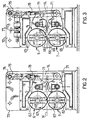
- the arms 71 that support the lower drum 7 are connected to a rod 74 (see Fig. 2) arranged from the top to the bottom with respect to the shearing device, by means of a large pivot fixed onto the frame 70 and parallel to the axis of the drums (only the intersection outline of this pivot with the plane of the drawing in Figs. 2 and 3 is visible); at the opposite end the rod 74 is connected to a crank 75 oscillating with respect to a cross-piece 76 of the frame 70, while a hydraulic actuator 77 is active at the connection point between rod and crank.
- the articulated system formed by the rod 74 and the crank 75 allows, depending on the state of activation of the actuator 77, a displacement of the hinging point of the two lever arms 71 associated with the lower drum 7 and hence a consequent oscillation thereof which causes displacement of the drum itself; owing to the engagement between the toothings 73, the oscillation of each arm 71 which supports the lower drum 7 is transmitted to the corresponding arm for the upper drum 6, thereby causing simultaneous and opposed displacement of the two drums.
- the drums are kept in a position close to one another in the configuration of Fig. 2, wherein the rod 74 is kept in alignment with the crank 75 by the actuator 77 and hence the lever arms 71 are locked; for opening the drums, on the other hand, the actuator 77 is moved such that the point of connection between the rod and the crank can be displaced by moving the lever arms 71.
- the divider 3 contains inside it a gearing 80 consisting of a pair of large modular toothed wheels 81 and 82, the former being associated to the upper drum 6 whilst the latter to the lower one 7, respectively by means of the shafts 4 and 5; furthermore, the wheel 81 receives the movement from the motor 2 to which it is connected and causes rotation of the wheel 82, that is then driven by it.
- the radius R1 of the pitch circumference and the number of teeth Z1 of the toothed wheel 81 are respectively less than the corresponding radius R2 and number of teeth Z2 of the wheel 82, whilst the pitches P1 and P2 of the teeth are the same;
- the transmission ratio "i" of the gearing regarded as the ratio between ⁇ 1 and ⁇ 2, is equal to the inverted ratio of the number of teeth, i.e. Z2/Z1, in accordance with the well-known formulae for which reference should be made to technical literature on the subject; in the light of what has been stated above in connection with the various parameters of the gearing, the drive wheel 81 and the upper drum 6 will therefore rotate at a higher number of revolutions than the driven wheel 82 and the lower drum 7.
- the diameters of the drums and their position relative to each other are such that they have the same peripheral speed (i.e. the product of the angular speed of rotation ⁇ with the radius r of the drum) although they rotate at a different number of revolutions from one another; this in order to obtain conditions of synchronism between the peripheral speed of both of them and the feed speed of the strip N to be cut.
- Fig. 3 shows the profile of three rollers provided for this purpose and arranged downstream of the cutting zone of the shearing device.
- the blades 68 rotating at respective constant angular speeds ⁇ 1 and ⁇ 2 which differ from each other and correspond to those of the associated drums, reach the condition where they are located opposite one another (as in Fig. 2) in the plane which contains the axes of rotation of the drums: at this point the cutting edge of the blades comes into contact with the strip N which is then cut in a manner similar to what happens in traditional shears.
- the drums After cutting, the drums are moved away from each other while continuing to rotate; this movement away may be performed over a sufficiently length of time to avoid the drawbacks mentioned above, even though processing is performed with high feeding speeds of the strip.
- phase-displacement in the position of the two blades, which gradually increases during the subsequent rotations, said blades do not interfere with the advancing strip immediately after cutting; obviously the degree of phase-displacement in question may vary from case to case, depending on the various operational parameters of the shearing device and production, such as for example the type and the material of the product to be cut, its thickness, the feed speed with which it is supplied, the type of blade used, the diameter of the drums, as well as the number of revolutions per minute, and so on.
- N1 Zp/Z1 for the toothed wheel 81 and the drum 6
- N2 Zp/Z2 for the toothed wheel 82 and the drum 7.
- the movement away of the drums may therefore be performed over relatively long periods of time compared to those which would be necessary in the case, for the same feeding speed of the material to be cut, a shearing device is used having drums rotating in synchronism, as it occurs in the present state of the art.
- this interval may be easily determined on the basis of the relationships indicated above with regard to the toothed wheels of the gearing.
- a first possible change which appears to be fairly evident at first sight consists in replacing the single motor 2 and the divider 3 with two separate motors, each of which is intended for driving a respective drum with a number of revolutions different from that of the other drum, thus obtaining the same result of having two separate speeds of rotation ⁇ 1 and ⁇ 2 with the effects arising therefrom and already explained.
- the divider wherein two different toothed wheels are used in order to obtain a transmission ratio which is not unitary, is particularly advantageous because it is simple to provide and hence without additional costs with respect to the dividers currently in use, wherein pairs of twin toothed wheels are applied; it is however obvious that, in order to have downstream of the motor two shafts rotating at different speeds, various divider systems which obtain the same result may be envisaged.
- shearing devices may be provided with drums having two or more blades instead of the single one considered previously; for example, on the periphery of a drum there might be two blades in a diametrically opposite position or a greater number of them located uniformly or even irregularly.
- the mechanisms for closing and opening the drums may also differ from that described in the example, i.e. the articulated system consisting of the rod 74, the crank 75, the actuator 77 and the spring 80, with the associated pins and connecting cross-pieces.
- drums could also be supported differently from the oscillating arms and their structure could also be subject to changes or be adapted to each situation, depending on the various possible purposes which the shearing device according to the invention may have, as mentioned at the beginning.
Landscapes
- Engineering & Computer Science (AREA)
- Mechanical Engineering (AREA)
- Life Sciences & Earth Sciences (AREA)
- Forests & Forestry (AREA)
- Physics & Mathematics (AREA)
- Fluid Mechanics (AREA)
- Shearing Machines (AREA)
- Apparatuses For Bulk Treatment Of Fruits And Vegetables And Apparatuses For Preparing Feeds (AREA)
- Formation And Processing Of Food Products (AREA)
Abstract
Description
- Fig. 1 shows a front perspective view of a shearing device in accordance with the invention;
- Figures 2 and 3 are respective views, sectioned along the lines II-II and III-III in Figure 1, of the shearing device shown therein;
- Fig. 4 shows in detail a gearing of the divider mechanism relating to the shearing device of the preceding figures.
Claims (13)
- Method for cutting continuously supplied material by means of a pair of counter-rotating drums (6, 7) arranged side by side, between which the material is fed and provided with respective blades (68) that cut the material acting on opposite sides thereof when, following to the rotation of the corresponding drum, they are located in a substantially opposed position, characterized in that the drums rotate with respective angular speeds (ω1, ω2) different from one another.
- Method according to Claim 1, wherein the drums (6, 7) are moved away from the material after cutting.
- Method according to Claim 1 or 2, wherein the drums are cylindrically shaped with respective external diameters different from one another and rotate so as to have substantially the same peripheral speeds.
- Method according to any of the preceding claims, wherein the peripheral speeds of the drums are substantially the same as the feeding speed of the material to be cut.
- Method according to any of the preceding claims, wherein the material to be cut is supplied at a feed speed greater than 10 m/s.
- Method according to any of the preceding claims, wherein the material to be cut is a metal strip.
- Shearing device for carrying out the method according to any of the preceding claims, comprising a pair of drums (6, 7) arranged side by side and rotatably supported by a supporting structure (70), drive means (2), transmission means (3, 4, 5, 80-82) which connect said drive means to the drums (6, 7) for rotation thereof, characterized in that the drive means (2) and transmission means (3, 4, 5, 80-82) are designed to cause rotation of the drums at respective angular speeds (ω1, ω2) different from one another.
- Shearing device according to Claim 7, wherein the drive means (2) and the transmission means (3, 4, 5, 80-82) comprise two separate motors, each of which is connected to a respective drum (6, 7).
- Shearing device according to Claim 7, wherein the transmission means comprise a divider mechanism (3) which is associated to the drive means (2) and which transmits downstream thereof a respective rotary movement to the two drums (6, 7) with angular speeds (ω1, ω2) of rotation different from one another.
- Shearing device according to Claim 9, wherein the divider mechanism comprises a gearing (80) formed by a pair of toothed wheels (81, 82) different from each other, one of them receiving the motion from the drive means (2) whilst the other being driven by the former and where each of these wheels is associated with a respective drum (6, 7) to whom it applied the rotary movement, thereby imparting to the drums the respective different angular speeds (ω1, ω2) of rotation.
- Shearing device according to Claim 10, wherein each toothed wheel (81, 82) rotates at the same angular speed (ω1, ω2) as the drum (6, 7) associated therewith.
- Shearing device according to any of Claims 7 to 11, wherein the drums (6, 7) are supported by means of oscillating lever arms (71).
- Shearing device according to Claim 12, wherein each lever arm (71) of a drum is provided with a toothing (73) and oscillates in a same plane as that of an opposite lever arm which supports the other drum, and wherein the toothings of the lever arms of a drum engage with those of the respectively opposite arm of the other drum, thereby transmitting the oscillating movement of one toothing to the other and moving together the drums from and towards the material to be cut.
Applications Claiming Priority (2)
| Application Number | Priority Date | Filing Date | Title |
|---|---|---|---|
| ITMI972201 | 1997-09-29 | ||
| IT97MI002201A IT1295234B1 (en) | 1997-09-29 | 1997-09-29 | METHOD AND EQUIPMENT FOR CUTTING CONTINUOUSLY FED MATERIAL |
Publications (3)
| Publication Number | Publication Date |
|---|---|
| EP0904877A2 true EP0904877A2 (en) | 1999-03-31 |
| EP0904877A3 EP0904877A3 (en) | 1999-07-28 |
| EP0904877B1 EP0904877B1 (en) | 2003-01-29 |
Family
ID=11377945
Family Applications (1)
| Application Number | Title | Priority Date | Filing Date |
|---|---|---|---|
| EP97830621A Expired - Lifetime EP0904877B1 (en) | 1997-09-29 | 1997-11-26 | Apparatus for cutting continuously supplied material |
Country Status (5)
| Country | Link |
|---|---|
| EP (1) | EP0904877B1 (en) |
| JP (1) | JP4335333B2 (en) |
| AT (1) | ATE231765T1 (en) |
| DE (1) | DE69718785T2 (en) |
| IT (1) | IT1295234B1 (en) |
Cited By (4)
| Publication number | Priority date | Publication date | Assignee | Title |
|---|---|---|---|---|
| US7117776B1 (en) | 1999-11-10 | 2006-10-10 | Sms Demag Ag | High-speed shear for transverse cutting of a rolled strip |
| CN102808314A (en) * | 2012-08-27 | 2012-12-05 | 台州东海塑料品制造有限公司 | Automatic edge cutter of textilene mesh fabric setting machine |
| US8683898B2 (en) | 2000-01-19 | 2014-04-01 | Sms Siemag Aktiengesellschaft | Method of operating a high-speed shear |
| CN104139422A (en) * | 2014-07-30 | 2014-11-12 | 泉州市汉威机械制造有限公司 | Full-automatic phase regression control method |
Families Citing this family (1)
| Publication number | Priority date | Publication date | Assignee | Title |
|---|---|---|---|---|
| DE102014005998B3 (en) * | 2014-04-28 | 2015-05-13 | Fritsch Gmbh | Method and device for producing blanks of dough pieces from one or more dough sheets |
Family Cites Families (2)
| Publication number | Priority date | Publication date | Assignee | Title |
|---|---|---|---|---|
| DE2138478A1 (en) * | 1971-07-31 | 1973-02-15 | Demag Ag | ROTARY KNIFE SHEARS |
| JPS5816970B2 (en) * | 1975-12-04 | 1983-04-04 | 川崎重工業株式会社 | Kaiten Drum Gatasou Kanbun Katsusendanki |
-
1997
- 1997-09-29 IT IT97MI002201A patent/IT1295234B1/en active IP Right Grant
- 1997-11-26 EP EP97830621A patent/EP0904877B1/en not_active Expired - Lifetime
- 1997-11-26 AT AT97830621T patent/ATE231765T1/en active
- 1997-11-26 DE DE69718785T patent/DE69718785T2/en not_active Expired - Lifetime
-
1998
- 1998-09-22 JP JP26797198A patent/JP4335333B2/en not_active Expired - Fee Related
Cited By (6)
| Publication number | Priority date | Publication date | Assignee | Title |
|---|---|---|---|---|
| US7117776B1 (en) | 1999-11-10 | 2006-10-10 | Sms Demag Ag | High-speed shear for transverse cutting of a rolled strip |
| US8683898B2 (en) | 2000-01-19 | 2014-04-01 | Sms Siemag Aktiengesellschaft | Method of operating a high-speed shear |
| CN102808314A (en) * | 2012-08-27 | 2012-12-05 | 台州东海塑料品制造有限公司 | Automatic edge cutter of textilene mesh fabric setting machine |
| CN102808314B (en) * | 2012-08-27 | 2014-11-12 | 台州东海塑料品制造有限公司 | Automatic edge cutter of textilene mesh fabric setting machine |
| CN104139422A (en) * | 2014-07-30 | 2014-11-12 | 泉州市汉威机械制造有限公司 | Full-automatic phase regression control method |
| CN104139422B (en) * | 2014-07-30 | 2015-12-30 | 泉州市汉威机械制造有限公司 | A kind of full-automatic phase place rehabilitation control method |
Also Published As
| Publication number | Publication date |
|---|---|
| ATE231765T1 (en) | 2003-02-15 |
| ITMI972201A1 (en) | 1999-03-29 |
| EP0904877B1 (en) | 2003-01-29 |
| DE69718785T2 (en) | 2003-11-20 |
| IT1295234B1 (en) | 1999-05-04 |
| DE69718785D1 (en) | 2003-03-06 |
| JPH11235619A (en) | 1999-08-31 |
| JP4335333B2 (en) | 2009-09-30 |
| EP0904877A3 (en) | 1999-07-28 |
Similar Documents
| Publication | Publication Date | Title |
|---|---|---|
| US5315907A (en) | Machine for cutting logs of web material | |
| EP0507747A1 (en) | Perforating apparatus for paper webs and the like, with reciprocating motion of translation of the counterblade | |
| EP0904877B1 (en) | Apparatus for cutting continuously supplied material | |
| RU2262850C2 (en) | Method and apparatus for forming of dough piece | |
| JPH03196994A (en) | Travelling web cutting device adjustable relating to block size | |
| US3791244A (en) | Shearing machine for cutting of band material | |
| US3800640A (en) | Apparatus and method for cutting a travelling web of material | |
| US6032560A (en) | High speed trimming shear | |
| US3968713A (en) | Machine for cross-cutting a web of material | |
| CA1072004A (en) | Rotary shear machine | |
| US20010010144A1 (en) | Apparatus for sealing a wrapper film sleeve | |
| US5107901A (en) | Modulator mechanism for dobby | |
| US3068731A (en) | Shearing apparatus having rotary bearing means to predetermine the amount of overlap of rotary blades | |
| US3613471A (en) | Counterbalancing means for cutoff knives | |
| US3768365A (en) | Apparatus for providing partial slits in corrugated drain pipe | |
| JP2831179B2 (en) | Rotary drum type cutting device | |
| US4856396A (en) | Apparatus for selectively forming apertures or holes or venting pinholes in a continuously moving web | |
| US3136194A (en) | Paper-cutting and like machines | |
| US3618437A (en) | Machine for and process of die-cutting | |
| US5317942A (en) | Rotary perforator, method for perforating a web, and web perforated by the rotary perforator | |
| US4759246A (en) | Tumbling hole punch and method for punching holes into a moving web material | |
| US6272959B1 (en) | Continuously rotating shears | |
| KR200367820Y1 (en) | Manufacturing machine of a roll bag | |
| JPS5834710A (en) | Link type running shearing machine | |
| JPH0618738Y2 (en) | Rotary running shear device |
Legal Events
| Date | Code | Title | Description |
|---|---|---|---|
| PUAI | Public reference made under article 153(3) epc to a published international application that has entered the european phase |
Free format text: ORIGINAL CODE: 0009012 |
|
| AK | Designated contracting states |
Kind code of ref document: A2 Designated state(s): AT DE ES FR GB IT |
|
| AX | Request for extension of the european patent |
Free format text: AL;LT;LV;MK;RO;SI |
|
| PUAL | Search report despatched |
Free format text: ORIGINAL CODE: 0009013 |
|
| AK | Designated contracting states |
Kind code of ref document: A3 Designated state(s): AT BE CH DE DK ES FI FR GB GR IE IT LI LU MC NL PT SE |
|
| AX | Request for extension of the european patent |
Free format text: AL;LT;LV;MK;RO;SI |
|
| 17P | Request for examination filed |
Effective date: 20000117 |
|
| AKX | Designation fees paid |
Free format text: AT BE CH DE DK ES LI |
|
| RBV | Designated contracting states (corrected) |
Designated state(s): AT DE ES FR GB IT |
|
| 17Q | First examination report despatched |
Effective date: 20010503 |
|
| RTI1 | Title (correction) |
Free format text: APPARATUS FOR CUTTING CONTINUOUSLY SUPPLIED MATERIAL |
|
| RTI1 | Title (correction) |
Free format text: APPARATUS FOR CUTTING CONTINUOUSLY SUPPLIED MATERIAL |
|
| GRAG | Despatch of communication of intention to grant |
Free format text: ORIGINAL CODE: EPIDOS AGRA |
|
| RAP1 | Party data changed (applicant data changed or rights of an application transferred) |
Owner name: SMS DEMAG INNSE S.P.A. |
|
| GRAG | Despatch of communication of intention to grant |
Free format text: ORIGINAL CODE: EPIDOS AGRA |
|
| GRAH | Despatch of communication of intention to grant a patent |
Free format text: ORIGINAL CODE: EPIDOS IGRA |
|
| GRAH | Despatch of communication of intention to grant a patent |
Free format text: ORIGINAL CODE: EPIDOS IGRA |
|
| GRAA | (expected) grant |
Free format text: ORIGINAL CODE: 0009210 |
|
| AK | Designated contracting states |
Designated state(s): AT DE ES FR GB IT |
|
| REG | Reference to a national code |
Ref country code: GB Ref legal event code: FG4D |
|
| REF | Corresponds to: |
Ref document number: 69718785 Country of ref document: DE Date of ref document: 20030306 Kind code of ref document: P |
|
| PG25 | Lapsed in a contracting state [announced via postgrant information from national office to epo] |
Ref country code: ES Free format text: LAPSE BECAUSE OF FAILURE TO SUBMIT A TRANSLATION OF THE DESCRIPTION OR TO PAY THE FEE WITHIN THE PRESCRIBED TIME-LIMIT Effective date: 20030730 |
|
| ET | Fr: translation filed | ||
| PG25 | Lapsed in a contracting state [announced via postgrant information from national office to epo] |
Ref country code: GB Free format text: LAPSE BECAUSE OF NON-PAYMENT OF DUE FEES Effective date: 20031126 |
|
| PLBE | No opposition filed within time limit |
Free format text: ORIGINAL CODE: 0009261 |
|
| STAA | Information on the status of an ep patent application or granted ep patent |
Free format text: STATUS: NO OPPOSITION FILED WITHIN TIME LIMIT |
|
| 26N | No opposition filed |
Effective date: 20031030 |
|
| GBPC | Gb: european patent ceased through non-payment of renewal fee |
Effective date: 20031126 |
|
| PGFP | Annual fee paid to national office [announced via postgrant information from national office to epo] |
Ref country code: AT Payment date: 20131101 Year of fee payment: 17 Ref country code: DE Payment date: 20131127 Year of fee payment: 17 Ref country code: FR Payment date: 20131118 Year of fee payment: 17 |
|
| REG | Reference to a national code |
Ref country code: DE Ref legal event code: R119 Ref document number: 69718785 Country of ref document: DE |
|
| REG | Reference to a national code |
Ref country code: AT Ref legal event code: MM01 Ref document number: 231765 Country of ref document: AT Kind code of ref document: T Effective date: 20141126 |
|
| REG | Reference to a national code |
Ref country code: FR Ref legal event code: ST Effective date: 20150731 |
|
| PG25 | Lapsed in a contracting state [announced via postgrant information from national office to epo] |
Ref country code: AT Free format text: LAPSE BECAUSE OF NON-PAYMENT OF DUE FEES Effective date: 20141126 |
|
| PG25 | Lapsed in a contracting state [announced via postgrant information from national office to epo] |
Ref country code: DE Free format text: LAPSE BECAUSE OF NON-PAYMENT OF DUE FEES Effective date: 20150602 |
|
| PG25 | Lapsed in a contracting state [announced via postgrant information from national office to epo] |
Ref country code: FR Free format text: LAPSE BECAUSE OF NON-PAYMENT OF DUE FEES Effective date: 20141201 |
|
| PGFP | Annual fee paid to national office [announced via postgrant information from national office to epo] |
Ref country code: IT Payment date: 20151126 Year of fee payment: 19 |
|
| PG25 | Lapsed in a contracting state [announced via postgrant information from national office to epo] |
Ref country code: IT Free format text: LAPSE BECAUSE OF NON-PAYMENT OF DUE FEES Effective date: 20161126 |