EP0904856A2 - High pressure cleaner with removable handle - Google Patents
High pressure cleaner with removable handle Download PDFInfo
- Publication number
- EP0904856A2 EP0904856A2 EP98118375A EP98118375A EP0904856A2 EP 0904856 A2 EP0904856 A2 EP 0904856A2 EP 98118375 A EP98118375 A EP 98118375A EP 98118375 A EP98118375 A EP 98118375A EP 0904856 A2 EP0904856 A2 EP 0904856A2
- Authority
- EP
- European Patent Office
- Prior art keywords
- cleaning device
- pressure cleaning
- basic housing
- push
- push bracket
- Prior art date
- Legal status (The legal status is an assumption and is not a legal conclusion. Google has not performed a legal analysis and makes no representation as to the accuracy of the status listed.)
- Granted
Links
- 239000004033 plastic Substances 0.000 claims abstract description 20
- 239000000126 substance Substances 0.000 claims abstract description 5
- 238000004140 cleaning Methods 0.000 claims description 24
- 238000003860 storage Methods 0.000 claims description 4
- 238000002347 injection Methods 0.000 abstract description 2
- 239000007924 injection Substances 0.000 abstract description 2
- 238000001746 injection moulding Methods 0.000 abstract 1
- 239000002991 molded plastic Substances 0.000 abstract 1
- 239000000463 material Substances 0.000 description 4
- 238000013016 damping Methods 0.000 description 2
- 238000004519 manufacturing process Methods 0.000 description 2
- 239000002184 metal Substances 0.000 description 2
- 229920001875 Ebonite Polymers 0.000 description 1
- 230000005540 biological transmission Effects 0.000 description 1
- 238000010276 construction Methods 0.000 description 1
- 238000009826 distribution Methods 0.000 description 1
- 229920001971 elastomer Polymers 0.000 description 1
- 239000000806 elastomer Substances 0.000 description 1
- 239000000243 solution Substances 0.000 description 1
- 239000007921 spray Substances 0.000 description 1
- 238000009423 ventilation Methods 0.000 description 1
Images


Classifications
-
- B—PERFORMING OPERATIONS; TRANSPORTING
- B08—CLEANING
- B08B—CLEANING IN GENERAL; PREVENTION OF FOULING IN GENERAL
- B08B3/00—Cleaning by methods involving the use or presence of liquid or steam
- B08B3/02—Cleaning by the force of jets or sprays
- B08B3/026—Cleaning by making use of hand-held spray guns; Fluid preparations therefor
-
- F—MECHANICAL ENGINEERING; LIGHTING; HEATING; WEAPONS; BLASTING
- F04—POSITIVE - DISPLACEMENT MACHINES FOR LIQUIDS; PUMPS FOR LIQUIDS OR ELASTIC FLUIDS
- F04B—POSITIVE-DISPLACEMENT MACHINES FOR LIQUIDS; PUMPS
- F04B35/00—Piston pumps specially adapted for elastic fluids and characterised by the driving means to their working members, or by combination with, or adaptation to, specific driving engines or motors, not otherwise provided for
- F04B35/06—Mobile combinations
-
- B—PERFORMING OPERATIONS; TRANSPORTING
- B08—CLEANING
- B08B—CLEANING IN GENERAL; PREVENTION OF FOULING IN GENERAL
- B08B2203/00—Details of cleaning machines or methods involving the use or presence of liquid or steam
- B08B2203/02—Details of machines or methods for cleaning by the force of jets or sprays
- B08B2203/0276—Hose reels specific for high pressure cleaners
Definitions
- the invention relates to a high-pressure cleaning device a base frame on which two spaced apart on an axis Wheels are arranged and the one in its front Area at a distance from the axis of a support part for support on the floor.
- Such housings for high pressure cleaning devices are in various embodiments have become known. You point a push handle, with the aim that the pressure washer is easy to move.
- the known push bars have the disadvantage that they not from an injection molded frame-like plastic part exist and therefore only with high manufacturing costs are to be produced. It is known here to push the push bar e.g. to be made from a metal part, from a combined one To manufacture metal-plastic part and the like.
- the invention is therefore based on the object High pressure cleaning device with removable push handle at the entrance mentioned type so that the push handle as shell-like part easily detachable with the basic housing of the High pressure cleaning device can be connected and that High-pressure cleaning device with the push handle removed has a relatively low height.
- the invention is thereby characterized in that the push bar from a shell-like Plastic part with two opposite and parallel side cheeks are formed, which Sidewalls in their upper area by a common, the cross member connecting the side bolsters connected to each other are.
- connection level between the Push bar and the main housing of the high-pressure cleaning device is formed as close as possible to the basic housing. This measure leads to the fact that the basic housing is removed when the push handle is removed has a relatively low overall height.
- connection level between the push bar and the support level of the basic housing lies underneath the removable hood for the basic housing, because this ensures an optimally low overall height of the high-pressure cleaning device reached with the push handle removed.
- the easy disassembly of the push handle has it Another advantage that the rest of the assembly Parts of the high-pressure cleaning device, namely in particular the Bracket of the motor pump unit on the basic housing, light become accessible.
- the front, middle foot bearing is height adjustable, so that Motor pump unit by the setting on the foot side Bearing can be pivoted, the pivot axis in Area of the rear bearing.
- Basic housing is a chemical tank integrated into the shell-like basic housing with a hollow body is involved.
- bearing blocks arranged on the push bracket are between which a hose reel is received, and that there is also a storage tray on the push bar, which is arranged in the lower area of the push bar and which further improves the torsional stiffness of the push handle.
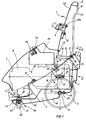
- reference number 1 shows a push handle shown, which consists of a bowl-like, multi-part Plastic part is made.
- the cross bar 2 is, however, vertical Divided direction so that the push bar is in a front, bowl-like part and into a rear bowl-like part divided, the parting line between the two parts approximately lies in the vertical plane.
- the two shell-like parts of the Push bars are via appropriate fastening screws interconnected so that the connection is stiff and firm are trained.
- the two plastic parts of the push bracket 1 are in here the parting plane 41 connected to one another, as shown in FIG. 1 is shown.
- the rear plastic part 42 is therefore designed much smaller than the front plastic part 43, the two plastic parts 42, 43 each belonging to the complete push handle 1 in the area of parting line 41 unite.
- FIG Recording 10 provided for receiving a bearing block 9.
- this bracket is disassembled and it is a cover-like Part available, which with the help of screws 12 closes this receptacle 10.
- Push bracket 1 each have a bearing block 9 with screws 12, 12a mounted, which is capable of a corresponding transverse axis record a hose reel, not shown.
- the basic housing 3 of the high-pressure cleaning device is also made of plastic tub-like and has here raised sidewalls 14 in the rear area, which in this Pass the area into a chemical tank 13, which in Sidewalls 14 is integrated and transversely the rear wall of the Basic housing 3 forms according to Figure 2.
- the upper edge of the basic housing 3 forms an oblique front inclined support surface (support 15), which are arched forward and downward and which in their front area into a backward inclined surface 31 passes, which delimits a cutout 32 in the front area.
- Directed axes 22 is provided, these stub axles attached to the rear engine cover of the engine assembly 7 are.
- the axes 22 engage in bearings 23, respectively approximately circular cylindrical with a central recess are formed, the bearings 23 either from a Elastomer material can consist of a hard rubber or from another vibration-damping material, e.g. one Metal element or the like.
- the bearings 23 in turn are each from above through a half shell 24 covered, with each half shell 24 by front and rear Screws 25 on assigned mounting surfaces on Basic housing are attached.
- the front support of the motor pump unit 7.8 takes place here by a front foot, which is essentially as Support part 27 is formed for support on the floor.
- This support part 27 has a recess 28 in which an adjusting screw 30 with a nut 29 is adjustable in height is held.
- the entire motor pump unit 7,8 can be removed upwards provided the half shells 24 to the as a pivot bearing trained bearings 21 are removed.
- the hood 4 namely covers the front part of the high-pressure cleaning device and in particular the motor pump unit 7.8 from the front, with the hood using two from each other spaced hood fastenings 37 on the support 15 of the Basic housing 3 is attached.
- the rear attachment of the Hood 4 takes place in the area of the push bracket 1 via the Attachment 45.
- a switch box 38 is also provided with the motor pump unit connected, which contains the electrical functional parts.
- a switch button 39 protrudes from the top of the switch box 38 out of this and reaches through a cutout 40 the hood 4 through.
- the axis 6 is also according to Figure 1 with a half-shell Construction with the underside of the basic housing 3 connected, the basic housing on its lower edge 46 a circular receptacle 47 open towards the front, in which engages the axis 6 approximately positively and by means of a half shell 48 is secured against falling out, which Half-shell 48 by means of a screw 49 on the basic housing 3 is attached.
- the advantage of the solution proposed according to the invention is therefore that a relatively large push handle is provided, that of two shell-like plastic parts 42,43, which together form the approximately U-shaped Form push bracket 1, the connecting leg of this U-shaped Push bracket 1 is formed by the cross member 2.
- the connection level between the push bar 1 and the Basic housing 3 in the area of an inclined forward Support 15 is arranged, which support as close as possible is arranged above the floor, there is the advantage that on the one hand, a cheap one when the push handle is installed Power transmission to the basic housing 3 when pushing the Device is guaranteed and on the other hand when removed Push bar the device has a low overall height.
- Push bar a relatively straight and vertical (standing) position has, so its central axis is relatively perpendicular is aligned and essentially on the axis of the Chassis is aligned so that an optimal weight distribution given is.
- the device itself (with lying aggregates) the character of a standing device awarded because the push handle is designed upright and is not inclined at an angle to the rear. this leads to to the fact that it lies above the driving axis.
Landscapes
- Engineering & Computer Science (AREA)
- Mechanical Engineering (AREA)
- General Engineering & Computer Science (AREA)
- Cleaning By Liquid Or Steam (AREA)
- Handcart (AREA)
- Pens And Brushes (AREA)
- Disintegrating Or Milling (AREA)
- Catching Or Destruction (AREA)
Abstract
Description
Gegenstand der Erfindung ist ein Hochdruckreinigungsgerät mit einem Grundrahmen, an dem an einer Achse zwei voneinander beabstandete Räder angeordnet sind und der in seinem vorderen Bereich im Abstand von der Achse ein Auflageteil zur Auflage auf den Boden aufweist.The invention relates to a high-pressure cleaning device a base frame on which two spaced apart on an axis Wheels are arranged and the one in its front Area at a distance from the axis of a support part for support on the floor.
Derartige Gehäuse für Hochdruckreinigungsgeräte sind in vielfältigen Ausführungsformen bekannt geworden. Sie weisen einen Schubbügel auf, mit dem Ziel, daß der Hochdruckreiniger leicht verfahrbar ist.Such housings for high pressure cleaning devices are in various embodiments have become known. You point a push handle, with the aim that the pressure washer is easy to move.
Hierbei ist es bekannt, den Schubbügel werkstoffeinstückig mit dem Grundgehäuse des Hochdruckreinigungsgeräts zu verbinden, was jedoch mit dem Nachteil eines relativ sperrigen Aufbaus verbunden ist. Ein derartiger Hochdruckreiniger kann beispielsweise nicht in engen Kofferräumen von Kfz. untergebracht werden.It is known to use the push handle in one piece to connect the basic housing of the high-pressure cleaning device, but with the disadvantage of a relatively bulky structure connected is. Such a pressure washer can for example not in the tight trunk of a car. be accommodated.
Es ist ebenso bekannt, derartige Schubbügel lösbar an dem
Grundgehäuse des Hochdruckreinigers anzuordnen. Bei dieser
bekannten Ausführungsform besteht aber der Nachteil, daß der
Schubbügel nur schwer lösbar an dem Hochdruckreiniger
befestigbar ist.
Bei den bekannten Hochdruckreinigern ist es bekannt, den
Schubbügel lösbar mit dem Grundgehäuse des Hochdruckreinigungsgeräts
zu verbinden. Diese Verbindungsarten haben aber den
Nachteil, daß die Höhe des Grundgehäuses auch bei abgenommenem
Schubbügel so hoch ist, daß es nur schwer in engen Transporträumen
zu stauen ist.It is also known to releasably arrange such push bars on the basic housing of the high-pressure cleaner. In this known embodiment, however, there is the disadvantage that the push bracket can be attached to the high-pressure cleaner only with difficulty.
In the known high-pressure cleaners, it is known to releasably connect the push bracket to the basic housing of the high-pressure cleaning device. However, these types of connections have the disadvantage that the height of the basic housing is so high, even when the push handle is removed, that it is difficult to stow in narrow transport spaces.
Ferner haben die bekannten Schubbügel den Nachteil, daß sie nicht aus einem gespritzten zargenartigen Kunststoffteil bestehen und deshalb nur mit hohen Herstellungskosten herzustellen sind. Es ist hierbei bekannt, die Schubbügel z.B. aus einem Metallteil zu fertigen, aus einem kombinierten Metall-Kunststoffteil und dergleichen mehr herzustellen.Furthermore, the known push bars have the disadvantage that they not from an injection molded frame-like plastic part exist and therefore only with high manufacturing costs are to be produced. It is known here to push the push bar e.g. to be made from a metal part, from a combined one To manufacture metal-plastic part and the like.
Der Erfindung liegt deshalb die Aufgabe zugrunde, ein Hochdruckreinigungsgerät mit abnehmbarem Schubbügel der eingangs genannten Art so weiterzubilden, daß der Schubbügel als schalenartiges Teil leicht lösbar mit dem Grundgehäuse des Hochdruckreinigungsgeräts verbunden werden kann und daß das Hochdruckreinigungsgerät bei abgenommenem Schubbügel eine relativ geringe Höhe aufweist.The invention is therefore based on the object High pressure cleaning device with removable push handle at the entrance mentioned type so that the push handle as shell-like part easily detachable with the basic housing of the High pressure cleaning device can be connected and that High-pressure cleaning device with the push handle removed has a relatively low height.
Zur Lösung der gestellten Aufgabe ist die Erfindung dadurch gekennzeichnet, daß der Schubbügel aus einem schalenartigen Kunstoffteil mit zwei einander gegenüberliegenden und parallel zueinander liegenden Seitenwangen ausgebildet ist, welche Seitenwangen in ihrem oberen Bereich durch einen gemeinsamen, die Seitenwangen verbindenden Querholm miteinander verbunden sind.To achieve the object, the invention is thereby characterized in that the push bar from a shell-like Plastic part with two opposite and parallel side cheeks are formed, which Sidewalls in their upper area by a common, the cross member connecting the side bolsters connected to each other are.
Hierbei ist wichtig, daß die Verbindungsebene zwischen dem Schubbügel und dem Grundgehäuse des Hochdruckreinigungsgeräts möglichst nahe am Grundgehäuse ausgebildet ist. Diese Maßnahme führt dazu, daß bei abgenommenem Schubbügel das Grundgehäuse eine relativ geringe Bauhöhe aufweist.It is important that the connection level between the Push bar and the main housing of the high-pressure cleaning device is formed as close as possible to the basic housing. This measure leads to the fact that the basic housing is removed when the push handle is removed has a relatively low overall height.
Hierbei wird es bevorzugt, wenn die Verbindungsebene zwischen dem Schubbügel und der Auflageebene des Grundgehäuses noch unterhalb der abnehmbaren Haube für das Grundgehäuse liegt, weil hierdurch eine optimal niedrige Bauhöhe des Hochdruckreinigungsgeräts bei abgenommenem Schubbügel erreicht wird.It is preferred if the connection level between the push bar and the support level of the basic housing lies underneath the removable hood for the basic housing, because this ensures an optimally low overall height of the high-pressure cleaning device reached with the push handle removed.
In einer Weiterbildung der vorliegenden Erfindung ist es vorgesehen, daß bei abgenommenem Schubbügel weitere wichtige Teile des Hochdruckreinigungsgeräts zugänglich werden, die andernfalls nur sehr schwierig zugänglich sind.In a development of the present invention, it is provided that with the push handle removed, further important Parts of the high-pressure cleaning device become accessible otherwise they are very difficult to access.
Die leichte Demontierbarkeit des Schubbügels hat also den weiteren Vorteil, daß bei einer derartigen Montage die übrigen Teile des Hochdruckreinigungsgeräts, nämlich insbesondere die Halterung des Motorpumpenaggreggats am Grundgehäuse, leicht zugänglich werden.The easy disassembly of the push handle has it Another advantage that the rest of the assembly Parts of the high-pressure cleaning device, namely in particular the Bracket of the motor pump unit on the basic housing, light become accessible.
Besonders vorteilhaft ist es hierbei, wenn das vordere, mittlere Fusslager höheneinstellbar ausgebildet ist, so daß das Motorpumpenaggreggat durch die Einstellung an dem fuss-seitigen Lager verschwenkt werden kann, wobei die Schwenkachse im Bereich des hinteren Lagers liegt.It is particularly advantageous here if the front, middle foot bearing is height adjustable, so that Motor pump unit by the setting on the foot side Bearing can be pivoted, the pivot axis in Area of the rear bearing.
Damit ergibt sich der Vorteil, daß mit wenigen Teilen ein schwenkbares Motorpumpenaggreggat verwirklicht wird, welches in seiner Lage zu der darauf gesetzten Haube einstellbar ist.This has the advantage that a few parts pivotable motor pump unit is realized, which in its position to the hood placed on it is adjustable.
Im übrigen wird es auch noch bevorzugt, wenn in dem Grundgehäuse ein Chemikalientank integriert ist, der in das schalenartig ausgebildete Grundgehäuse als Hohlkörper mit einbezogen ist.Otherwise, it is also preferred if in the Basic housing is a chemical tank integrated into the shell-like basic housing with a hollow body is involved.
In einer Weiterbildung der vorliegenden Erfindung ist es im übrigen vorgesehen, daß am Schubbügel Lagerböcke angeordnet sind, zwischen denen eine Schlauchtrommel aufgenommen wird, und daß am Schubbügel ferner eine Ablageschale vorhanden ist, welche im unteren Bereich des Schubbügels angeordnet ist und die die Verwindungssteifigkeit des Schubbügels noch verbessert.In a development of the present invention, it is in rest provided that bearing blocks arranged on the push bracket are between which a hose reel is received, and that there is also a storage tray on the push bar, which is arranged in the lower area of the push bar and which further improves the torsional stiffness of the push handle.
Der Erfindungsgegenstand der vorliegenden Erfindung ergibt sich nicht nur aus dem Gegenstand der einzelnen Patentansprüche, sondern auch aus der Kombination der einzelnen Patentansprüche untereinander. The subject matter of the present invention results not only from the subject of the individual claims, but also from the combination of the individual Claims among themselves.
Alle in den Unterlagen, einschließlich der Zusammenfassung, offenbarten Angaben und Merkmale, insbesondere die in den Zeichnungen dargestellte räumliche Ausbildung werden als erfindungswesentlich beansprucht, soweit sie einzeln oder in Kombination gegenüber dem Stand der Technik neu sind. Im folgenden wird die Erfindung anhand von mehrere Ausführungswege darstellenden Zeichnungen näher erläutert. Hierbei gehen aus den Zeichnungen und ihrer Beschreibung weitere erfindungswesentliche Merkmale und Vorteile der Erfindung hervor.All in the documentation, including the summary, Disclosed information and features, in particular those in the Drawings illustrated spatial training are considered essential to the invention, insofar as they are used individually or in Combination are new compared to the prior art. In the following the invention based on several Drawings illustrating execution paths explained in more detail. Here go from the drawings and their description further features and advantages essential to the invention Invention.
Es zeigen:
- Figur 1:
- Seitenansicht eines Hochdruckreinigungsgeräts nach der Erfindung,
- Figur 2:
- die Rückansicht des Hochdruckreinigungsgeräts nach Figur 1,
- Figur 3:
- eine Detaildarstellung der Befestigung eines Lagerbockes für eine Schlauchtrommel bei abgenommenem Lagerbock,
- Figur 4:
- eine Ansicht wie in Fig. 2 in kompletter Rückansicht.
- Figure 1:
- Side view of a high pressure cleaning device according to the invention,
- Figure 2:
- the rear view of the high pressure cleaning device according to Figure 1,
- Figure 3:
- a detailed representation of the mounting of a bearing block for a hose reel with the bearing block removed,
- Figure 4:
- a view as in Fig. 2 in a complete rear view.
In der Darstellung ist mit Bezugszeichen 1 ein Schubbügel dargestellt, der aus einem schalenartigen, mehrteiligen Kunststoffteil besteht.In the illustration, reference number 1 shows a push handle shown, which consists of a bowl-like, multi-part Plastic part is made.
Es handelt sich hierbei um eine vordere Kunststoffschale und um
eine hintere Kunststoffschale, die über eine mittlere
Trennebene miteinander verbunden sind, so daß also der Querholm
2 sowohl mit der wangenartigen linken Seite des Schubbügels als
auch mit der wangenartigen rechten Seite des Schubbügels
jeweils verbunden ist. Der Querholm 2 ist jedoch in vertikaler
Richtung geteilt, so daß sich der Schubbügel in einen vorderen,
schalenartigen Teil und in einen hinteren schalenartigen Teil
unterteilt, wobei die Trennfuge zwischen den beiden Teilen etwa
in vertikaler Ebene liegt. Die beiden schalenartigen Teile des
Schubbügels sind über entsprechende Befestigungsschrauben
miteinander verbunden, so daß die Verbindung steif und fest
ausgebildet sind.It is a front plastic shell and
a rear plastic shell over a middle one
Parting plane are connected to each other, so that the
Die beiden Kunststoffteile des Schubbügels 1 sind hierbei in
der Trennebene 41 miteinander verbunden, so wie dies in Figur 1
dargestellt ist. Der hintere Kunststoffteil 42 ist also
wesentlich kleiner ausgebildet als der vordere Kunststoffteil
43, wobei die beiden Kunststoffteile 42,43 sich jeweils zu dem
kompletten Schubbügel 1 im Bereich der Trennebene 41
vereinigen.The two plastic parts of the push bracket 1 are in here
the
Im unteren Bereich des Schubbügels 1 ist hierbei eine
Quertraverse angeordnet, die als Ablageschale 16 ausgebildet
ist. Hierbei ist wichtig, daß diese Ablageschale werkstoffeinstückig
mit den beiden symmetrisch zueinander angeordneten
Kunststoffteilen 42,43 ausgebildet ist.In the lower area of the push bar 1 there is one
Crossbar arranged, which is designed as a
Hierdurch wird eine optimale Verwindungssteifigkeit des Schubbügels 1 insgesamt erreicht.This ensures an optimal torsional stiffness of the Push bar 1 reached in total.
Im oberen Bereich des Schubbügels (nämlich im Bereich des
vorderen Kunststoffteils 43) ist hierbei gemäss Figur 3 eine
Aufnahme 10 für die Aufnahme eines Lagerbocks 9 vorgesehen. In
Figur 3 ist dieser Lagerbock demontiert und es ist ein deckelartiges
Teil vorhanden, welches mit Hilfe von Schrauben 12
diese Aufnahme 10 verschließt.In the upper area of the push bar (namely in the area of the
front plastic part 43) is here according to FIG
Im montierten Zustand wird an jedem Kunststoffteil 43 des
Schubbügels 1 jeweils ein Lagerbock 9 mit Schrauben 12,12a
montiert, der in der Lage ist, eine entsprechende Querachse
einer nicht näher dargestellten Schlauchtrommel aufzunehmen. In the assembled
Ist die Schlauchtrommel nicht eingehängt, dann bildet das gezeigte abgekröpfte Teil des Lagerbocks 9 eine Aufnahme für die Sprühlanze und ggf. für die Hochdruckleitung.If the hose reel is not hooked in, then this forms shown cranked part of the bearing block 9 a receptacle for the spray lance and possibly for the high pressure line.
Das Grundgehäuse 3 des Hochdruckreinigungsgeräts ist ebenfalls
aus Kunststoff wannenartig ausgebildet und weist hierbei
erhöhte Seitenwangen 14 im hinteren Bereich auf, die in diesem
Bereich in einen Chemikalientank 13 übergehen, der in
Seitenwangen 14 integriert ist und quer die Rückwand des
Grundgehäuses 3 gemäss Figur 2 bildet.The
Der obere Rand des Grundgehäuses 3 bildet eine schräg nach
vorne geneigte Auflagefläche (Auflager 15), welche sich
bogenförmig nach vorne und unten erstreckt und welche in ihrem
vorderen Bereich in eine nach hinten geneigte Schrägfläche 31
übergeht, die einen Ausschnitt 32 im vorderen Bereich begrenzt.The upper edge of the
Auf dieses schräg nach unten verlaufende Auflager 15 wird der
Schubbügel 1 mit seinem unteren Ende gemäss Figur 1 aufgesetzt
und mit jeweils an jeder Seite angeordneten zwei Schrauben
17,19 mit dem Grundgehäuse 3 leicht lösbar verbunden. Hierbei
sind am Grundgehäuse 3 jeweils Gegenlager 18,20 angeordnet, in
welche die Schrauben 17,19 jeweils eingreifen und dort leicht
lösbar gehalten sind.On this obliquely downward bearing 15 is the
Push bar 1 with its lower end placed according to Figure 1
and with two screws on each
Diese Schrauben 17,19 (die jeweils paarweise vorhanden sind)
sind also durch die vordere, mittlere und zentrale Ausnehmung
des Schubbügels 1 leicht von vorne her zu erreichen, so daß der
Schubbügel leicht abnehmbar ausgebildet ist.These
Wichtig ist nun, daß bei Abnahme des Schubbügels 1 durch Lösen
der Schrauben 17,19 die wichtigen Befestigungslager für die
Befestigung des Motorpumpenaggreggats zugänglich werden.It is now important that when removing the push bar 1 by loosening
the
Hierzu ist vorgesehen, daß im Grundgehäuse 3 das Motorpumpenaggreggat
7,8 fest mit zueinander fluchtenden gegeneinander
gerichteten Achsen 22 versehen ist, wobei diese Achsstummel auf
dem rückwärtigen Motordeckel des Motoraggreggates 7 befestigt
sind. Die Achsen 22 greifen jeweils in Lagerungen 23 ein, die
etwa kreiszylindrisch mit einer mittleren Ausnehmung
ausgebildet sind, wobei die Lagerungen 23 entweder aus einem
Elastomer-Material bestehen können, aus einem Hartgummi oder
aus einem anderen schwingungsgedämpfen Material, wie z.B. einem
Metallelement oder dergleichen mehr. Die Lagerungen 23
ihrerseits sind jeweils von oben her durch eine Halbschale 24
abgedeckt, wobei jede Halbschale 24 durch vordere und hintere
Schrauben 25 an zugeordneten Befestigungsflächen am
Grundgehäuse befestigt sind.For this purpose it is provided that the motor pump unit in the
Die vordere Abstützung des Motorpumpenaggreggats 7,8 erfolgt
hierbei durch einen vorderen Fuß, der im wesentlichen als
Auflageteil 27 zur Abstützung auf dem Boden ausgebildet ist.
Dieses Auflageteil 27 weist eine Ausnehmung 28 auf, in welcher
höheneinstellbar eine Einstellschraube 30 mit einer Mutter 29
gehalten ist.The front support of the motor pump unit 7.8 takes place
here by a front foot, which is essentially as
Wird die Mutter 29 von der Einstellschraube 30 gelöst, dann
kann das gesamte Motorpumpenaggreggat 7,8 nach oben hin herausgenommen
werden, sofern die Halbschalen 24 an den als Drehlager
ausgebildeten Lagern 21 entfernt werden.If the
Wichtig ist, daß durch Verdrehung der Mutter 29 die
Einstellschraube 30 in ihrer Höhe verändert ist, wobei
gleichzeitig wesentlich ist, daß sich das Motorpumpenaggreggat
7,8 über ein Schwingungselement 44 auf dem Bodenlager 26
abstützt.It is important that the twist of the
Auf diese Weise ist also gesorgt, daß das gesamte Motorpumpenaggreggat
7,8 im Grundgehäuse 3 gehalten ist und an lediglich 3
Befestigungspunkten aufgehängt ist. In this way it is ensured that the entire
Wird die Einstellschraube 30 in Pfeilrichtungen 33,34
eingestellt, dann verschwenkt das gesamte Motorpumpenaggreggat
in der Pfeilrichtung 35 um die Achsen 22 als Drehlager. Auf
diese Weise wird sichergestellt, daß das Motorpumpenaggreggat
lagenrichtig zur Haube 4 des Hochdruckreinigungsgeräts
eingestellt werden kann.If the adjusting
Die Haube 4 deckt nämlich den vorderen Teil des Hochdruckreinigungsgeräts
und insbesondere das Motorpumpenaggreggat 7,8
von vorne her ab, wobei die Haube mittels zweier voneinander
beabstandeter Haubenfestigungen 37 an dem Auflager 15 des
Grundgehäuses 3 befestigt ist. Die rückwärtige Befestigung der
Haube 4 erfolgt hierbei im Bereich des Schubbügels 1 über die
Befestigung 45.The hood 4 namely covers the front part of the high-pressure cleaning device
and in particular the motor pump unit 7.8
from the front, with the hood using two from each other
spaced
Mit dem Motorpumpenaggreggat ist ferner ein Schaltkasten 38
verbunden, welcher die elektrischen Funktionsteile beinhaltet.
An der Oberseite des Schaltkastens 38 ragt ein Schaltknopf 39
aus diesem heraus und greift durch einen Ausschnitt 40 durch
die Haube 4 hindurch.A
Um nun das Hindurchgreifen dieses Schaltknopfes 39 auf dem
Ausschnitt 40 in der Haube einstellen zu können, ist die
beschriebene Schwenklagerung des Motorpumpenaggreggats 7,8
vorgesehen.To reach through this
Der Vollständigkeit halber ist noch erwähnt, daß in ansich
bekannter Weise an einer hinteren Achse 6 zwei voneinander
beabstandete Räder 5 angeordnet sind, welche drehbar auf der
Achse 6 gelagert sind, wobei diese Räder bevorzugt aus einem
Kunststoffmaterial bestehen und einen entsprechenden gummielastischen
Laufbelag tragen.For the sake of completeness it is mentioned that in itself
known manner on a
Die Achse 6 ist gemäss Figur 1 ebenfalls mit einer halbschalenartigen
Konstruktion mit der Unterseite des Grundgehäuses 3
verbunden, wobei das Grundgehäuse an seiner Unterkante 46 eine
nach vorne geöffnete kreisrunde Aufnahme 47 ausbildet, in
welche die Achse 6 etwa formschlüssig eingreift und mittels
einer Halbschale 48 vor dem Heraus fallen gesichert ist, welche
Halbschale 48 mittels einer Schraube 49 am Grundgehäuse 3
befestigt ist.The
Vorteil der Erfindungsgemäss vorgeschlagenen Lösung ist also,
daß ein relativ groß dimensionierter Schubbügel vorgesehen ist,
der aus zwei schalenartigen Kunststoffteilen
42,43 besteht, welche zusammen den etwa U-förmigen
Schubbügel 1 bilden, wobei der Verbindungsschenkel dieses U-förmigen
Schubbügels 1 durch den Querholm 2 gebildet wird.
Nachdem die Verbindungsebene zwischen dem Schubbügel 1 und dem
Grundgehäuse 3 im Bereich eines schräg nach vorne geneigten
Auflagers 15 angeordnet ist, welches Auflager möglichst dicht
über dem Boden angeordnet ist, ergibt sich der Vorteil, daß
einerseits bei montiertem Schubbügel eine günstige
Kraftübertragung auf das Grundgehäuse 3 beim Schieben des
Geräts gewährleistet ist und andererseits bei abgenommenem
Schubbügel das Gerät eine geringe Bauhöhe aufweist.The advantage of the solution proposed according to the invention is therefore
that a relatively large push handle is provided,
that of two shell-like
Weiterer Vorteil der vorliegenden Erfindung ist, daß der Schubbügel eine relativ gerade und vertikale (stehende) Lage hat, wobei seine Mittelachse also relativ senkrecht ausgerichtet ist und im wesentlichen auf der Achse des Fahrgestells fluchtet, so daß eine optimale Gewichtsverteilung gegeben ist. Damit wird dem ansich liegenden Gerät (mit liegenden Aggreggaten) der Charakter eines stehenden Geräts verliehen, weil der Schubbügel stehend ausgebildet ist und nicht schräg nach hinten geneigt ausgerichtet ist. Dies führt dazu, daß er also über der Fahrachse liegt. Another advantage of the present invention is that the Push bar a relatively straight and vertical (standing) position has, so its central axis is relatively perpendicular is aligned and essentially on the axis of the Chassis is aligned so that an optimal weight distribution given is. The device itself (with lying aggregates) the character of a standing device awarded because the push handle is designed upright and is not inclined at an angle to the rear. this leads to to the fact that it lies above the driving axis.
- 11
- SchubbügelPush handle
- 22nd
- QuerholmQuerholm
- 33rd
- GrundgehäuseBasic housing
- 44th
- HaubeHood
- 55
- Radwheel
- 66
- Achseaxis
- 77
- MotoraggregatEngine unit
- 88th
- Pumpepump
- 99
- LagerbockBearing block
- 1010th
- Aufnahmeadmission
- 1212th
-
Schrauben 12a
Screws 12a - 1313
- ChemikalientankChemical tank
- 1414
- SeitenwangeSidewall
- 1515
- AuflagerIn stock
- 1616
- AblageschaleStorage tray
- 1717th
- Schraubescrew
- 1818th
- GegenlagerCounter bearing
- 1919th
- Schraubescrew
- 2020th
- GegenlagerCounter bearing
- 2121
- DämpfungslagerDamping bearings
- 2222
- Achseaxis
- 2323
- LagerungenBearings
- 2424th
- HalbschaleHalf shell
- 2525th
- Schraubescrew
- 2626
- BodenlagerFloor storage
- 2727
- Auflageteil Support part
- 2828
- AusnehmungRecess
- 2929
- Muttermother
- 3030th
- EinstellschraubeAdjusting screw
- 3131
- SchrägflächeSloping surface
- 3232
- AusschnittNeckline
- 3333
- PfeilrichtungArrow direction
- 3434
- PfeilrichtungArrow direction
- 3535
- PfeilrichtungArrow direction
- 3737
- HaubenbefestigungHood attachment
- 3838
- SchaltkastenControl box
- 3939
- SchaltknopfSwitch button
- 4040
- AusschnittNeckline
- 4141
- TrennebeneDividing plane
- 4242
- KunststoffblasteilBlown plastic part
- 4343
- ""
- 4444
- SchwingungselementVibration element
- 4545
- BefestigungAttachment
- 4646
- UnterkanteLower edge
- 4747
- Aufnahmeadmission
- 4848
- HalbschaleHalf shell
- 4949
- Schraubescrew
- 5050
- LüftungsgitterVentilation grille
- 5151
- GriffmuldeRecessed grip
Claims (7)
Applications Claiming Priority (2)
| Application Number | Priority Date | Filing Date | Title |
|---|---|---|---|
| DE29717495U DE29717495U1 (en) | 1997-09-30 | 1997-09-30 | Pressure washer with removable push handle |
| DE29717495U | 1997-09-30 |
Publications (3)
| Publication Number | Publication Date |
|---|---|
| EP0904856A2 true EP0904856A2 (en) | 1999-03-31 |
| EP0904856A3 EP0904856A3 (en) | 1999-12-15 |
| EP0904856B1 EP0904856B1 (en) | 2003-01-22 |
Family
ID=8046686
Family Applications (1)
| Application Number | Title | Priority Date | Filing Date |
|---|---|---|---|
| EP98118375A Revoked EP0904856B1 (en) | 1997-09-30 | 1998-09-29 | High pressure cleaner with removable handle |
Country Status (4)
| Country | Link |
|---|---|
| EP (1) | EP0904856B1 (en) |
| AT (1) | ATE231419T1 (en) |
| DE (3) | DE29717495U1 (en) |
| DK (1) | DK0904856T3 (en) |
Cited By (2)
| Publication number | Priority date | Publication date | Assignee | Title |
|---|---|---|---|---|
| WO2013123967A1 (en) * | 2012-02-20 | 2013-08-29 | Alfred Kärcher Gmbh & Co. Kg | High-pressure cleaning apparatus |
| CN105050737A (en) * | 2013-03-22 | 2015-11-11 | 阿尔弗雷德·凯驰两合公司 | High-pressure cleaning tool |
Families Citing this family (5)
| Publication number | Priority date | Publication date | Assignee | Title |
|---|---|---|---|---|
| US20050082441A1 (en) * | 2003-10-20 | 2005-04-21 | Gilpatrick Richard J. | Frame for pressurized fluid apparatus |
| DE202014000718U1 (en) | 2014-01-25 | 2015-04-28 | Nilfisk Advance A/S | Cleaning device with holder for a spray gun or lance |
| CA3008538C (en) * | 2016-02-22 | 2023-06-13 | Tti (Macao Commerical Offshore) Limited | Modular power washer system, method and kit therefor |
| WO2018072156A1 (en) * | 2016-10-19 | 2018-04-26 | Tti (Macao Commercial Offshore) Limited | Compact power washer battery, motor and pump design |
| CN109763954A (en) * | 2019-03-26 | 2019-05-17 | 苏州甘泰精密机械有限公司 | A kind of hand-held self sucking high-pressure cleaning machine |
Family Cites Families (9)
| Publication number | Priority date | Publication date | Assignee | Title |
|---|---|---|---|---|
| DE913617C (en) * | 1953-04-12 | 1954-06-18 | Albert Ziegler Fa | Device provided with a support frame, particularly a portable motor pump |
| US4136840A (en) * | 1978-01-23 | 1979-01-30 | Bates Charles A | Cord take-up reel for an electric lawn mower |
| DE8605424U1 (en) * | 1986-02-28 | 1986-07-31 | Kögel, Manfred, 6940 Weinheim | Mobile compact boiler compressor |
| DE4108775A1 (en) * | 1991-03-18 | 1992-09-24 | Kaercher Gmbh & Co Alfred | HIGH PRESSURE CLEANER |
| DE9300786U1 (en) * | 1993-01-21 | 1993-03-11 | Kränzle, Josef, 7918 Illertissen | high pressure cleaner |
| DE9303648U1 (en) * | 1993-03-12 | 1993-06-24 | Friedrich Epple GmbH & Co Hochdruckreinigungsgeräte und Spezialreinigungsmaschinen KG, 6942 Mörlenbach | High pressure cleaning device |
| DE4327156C1 (en) * | 1993-08-12 | 1994-10-06 | Kaercher Gmbh & Co Alfred | Mobile high-pressure cleaning device |
| DE9317014U1 (en) * | 1993-11-06 | 1994-01-20 | Alfred Kärcher GmbH & Co, 71364 Winnenden | High pressure cleaning device |
| DE9403745U1 (en) * | 1994-03-05 | 1994-05-05 | Hans Einhell AG, 94405 Landau | high pressure cleaner |
-
1997
- 1997-09-30 DE DE29717495U patent/DE29717495U1/en not_active Expired - Lifetime
-
1998
- 1998-03-13 DE DE19810881A patent/DE19810881B4/en not_active Expired - Lifetime
- 1998-09-29 DK DK98118375T patent/DK0904856T3/en active
- 1998-09-29 AT AT98118375T patent/ATE231419T1/en not_active IP Right Cessation
- 1998-09-29 DE DE59806984T patent/DE59806984D1/en not_active Expired - Fee Related
- 1998-09-29 EP EP98118375A patent/EP0904856B1/en not_active Revoked
Cited By (2)
| Publication number | Priority date | Publication date | Assignee | Title |
|---|---|---|---|---|
| WO2013123967A1 (en) * | 2012-02-20 | 2013-08-29 | Alfred Kärcher Gmbh & Co. Kg | High-pressure cleaning apparatus |
| CN105050737A (en) * | 2013-03-22 | 2015-11-11 | 阿尔弗雷德·凯驰两合公司 | High-pressure cleaning tool |
Also Published As
| Publication number | Publication date |
|---|---|
| DE29717495U1 (en) | 1998-10-29 |
| DE59806984D1 (en) | 2003-02-27 |
| EP0904856B1 (en) | 2003-01-22 |
| DE19810881B4 (en) | 2004-02-12 |
| DK0904856T3 (en) | 2003-04-22 |
| ATE231419T1 (en) | 2003-02-15 |
| EP0904856A3 (en) | 1999-12-15 |
| DE19810881A1 (en) | 1999-04-01 |
Similar Documents
| Publication | Publication Date | Title |
|---|---|---|
| DE2848256C2 (en) | ||
| EP0904856B1 (en) | High pressure cleaner with removable handle | |
| EP2539212B1 (en) | Accommodating and positioning device for inserting and retaining at least partially pedal-operated two-wheeled vehicles in two-wheeled vehicle storage apparatuses in a defined position | |
| DE69728748T2 (en) | ADJUSTABLE SUPPORT DEVICE FOR A CHILDREN'S VEHICLE | |
| EP1432602A1 (en) | Carriage | |
| DE2848257A1 (en) | BUMPER ARRANGEMENT FOR MOTOR VEHICLES | |
| DE19813361C2 (en) | Storage of a motor pump unit in vibration-damped bearings | |
| DE4321652B4 (en) | Plastic handle for hand-operated chainsaws | |
| DE4126085A1 (en) | Support stand for trailer caravan - uses selectively displaceable connecting rod and winding mechanism | |
| DE3146815C2 (en) | Storage for a hose nozzle with a pistol grip when not in use | |
| EP0921869B1 (en) | Travelling high-pressure cleaning device | |
| CH662990A5 (en) | Electric independent wheel drive | |
| DE3933086A1 (en) | REAR ENTRY STEP FOR MOTOR VEHICLES | |
| DE3929704A1 (en) | ARMREST | |
| DE3016959C2 (en) | ||
| EP0906212B1 (en) | Hand cart | |
| EP0813915B1 (en) | High-pressure cleaner with a cover | |
| EP0813917B1 (en) | High-pressure cleaner with handle and accomodation for accessories | |
| DE69913585T2 (en) | Fender holder | |
| DE550030C (en) | Resilient connection of the ends of the supporting leaf spring with the wheel carriers or swing axles of motor vehicles | |
| DE882806C (en) | Motor vehicle with a center tube frame | |
| DE19843557B4 (en) | golf carts | |
| DE9305052U1 (en) | Mobile can milking system | |
| DE20021539U1 (en) | Skateboard device | |
| DE953320C (en) | Roof rack for motor vehicles |
Legal Events
| Date | Code | Title | Description |
|---|---|---|---|
| PUAI | Public reference made under article 153(3) epc to a published international application that has entered the european phase |
Free format text: ORIGINAL CODE: 0009012 |
|
| AK | Designated contracting states |
Kind code of ref document: A2 Designated state(s): AT CH DE DK ES FR GB IT LI NL |
|
| AX | Request for extension of the european patent |
Free format text: AL;LT;LV;MK;RO;SI |
|
| PUAL | Search report despatched |
Free format text: ORIGINAL CODE: 0009013 |
|
| AK | Designated contracting states |
Kind code of ref document: A3 Designated state(s): AT BE CH CY DE DK ES FI FR GB GR IE IT LI LU MC NL PT SE |
|
| AX | Request for extension of the european patent |
Free format text: AL;LT;LV;MK;RO;SI |
|
| 17P | Request for examination filed |
Effective date: 20000218 |
|
| AKX | Designation fees paid |
Free format text: AT CH DE DK ES FR GB IT LI NL |
|
| 17Q | First examination report despatched |
Effective date: 20020304 |
|
| GRAH | Despatch of communication of intention to grant a patent |
Free format text: ORIGINAL CODE: EPIDOS IGRA |
|
| GRAH | Despatch of communication of intention to grant a patent |
Free format text: ORIGINAL CODE: EPIDOS IGRA |
|
| GRAA | (expected) grant |
Free format text: ORIGINAL CODE: 0009210 |
|
| AK | Designated contracting states |
Kind code of ref document: B1 Designated state(s): AT CH DE DK ES FR GB IT LI NL |
|
| PG25 | Lapsed in a contracting state [announced via postgrant information from national office to epo] |
Ref country code: IT Free format text: LAPSE BECAUSE OF FAILURE TO SUBMIT A TRANSLATION OF THE DESCRIPTION OR TO PAY THE FEE WITHIN THE PRE;WARNING: LAPSES OF ITALIAN PATENTS WITH EFFECTIVE DATE BEFORE 2007 MAY HAVE OCCURRED AT ANY TIME BEFORE 2007. THE CORRECT EFFECTIVE DATE MAY BE DIFFERENT FROM THE ONE RECORDED.SCRIBED TIME-LIMIT Effective date: 20030122 Ref country code: FR Free format text: LAPSE BECAUSE OF FAILURE TO SUBMIT A TRANSLATION OF THE DESCRIPTION OR TO PAY THE FEE WITHIN THE PRESCRIBED TIME-LIMIT Effective date: 20030122 |
|
| REG | Reference to a national code |
Ref country code: GB Ref legal event code: FG4D Free format text: NOT ENGLISH |
|
| REG | Reference to a national code |
Ref country code: CH Ref legal event code: EP |
|
| REF | Corresponds to: |
Ref document number: 59806984 Country of ref document: DE Date of ref document: 20030227 Kind code of ref document: P |
|
| REG | Reference to a national code |
Ref country code: CH Ref legal event code: NV Representative=s name: LUCHS & PARTNER PATENTANWAELTE |
|
| REG | Reference to a national code |
Ref country code: DK Ref legal event code: T3 |
|
| GBT | Gb: translation of ep patent filed (gb section 77(6)(a)/1977) |
Effective date: 20030509 |
|
| PG25 | Lapsed in a contracting state [announced via postgrant information from national office to epo] |
Ref country code: ES Free format text: LAPSE BECAUSE OF FAILURE TO SUBMIT A TRANSLATION OF THE DESCRIPTION OR TO PAY THE FEE WITHIN THE PRESCRIBED TIME-LIMIT Effective date: 20030730 |
|
| PG25 | Lapsed in a contracting state [announced via postgrant information from national office to epo] |
Ref country code: GB Free format text: LAPSE BECAUSE OF NON-PAYMENT OF DUE FEES Effective date: 20030929 Ref country code: AT Free format text: LAPSE BECAUSE OF NON-PAYMENT OF DUE FEES Effective date: 20030929 |
|
| PGFP | Annual fee paid to national office [announced via postgrant information from national office to epo] |
Ref country code: NL Payment date: 20030929 Year of fee payment: 6 |
|
| PG25 | Lapsed in a contracting state [announced via postgrant information from national office to epo] |
Ref country code: LI Free format text: LAPSE BECAUSE OF NON-PAYMENT OF DUE FEES Effective date: 20030930 Ref country code: DK Free format text: LAPSE BECAUSE OF NON-PAYMENT OF DUE FEES Effective date: 20030930 Ref country code: CH Free format text: LAPSE BECAUSE OF NON-PAYMENT OF DUE FEES Effective date: 20030930 |
|
| PLBQ | Unpublished change to opponent data |
Free format text: ORIGINAL CODE: EPIDOS OPPO |
|
| PLBI | Opposition filed |
Free format text: ORIGINAL CODE: 0009260 |
|
| PLAX | Notice of opposition and request to file observation + time limit sent |
Free format text: ORIGINAL CODE: EPIDOSNOBS2 |
|
| EN | Fr: translation not filed | ||
| 26 | Opposition filed |
Opponent name: ALFRED KAERCHER GMBH & CO. Effective date: 20031022 |
|
| NLR1 | Nl: opposition has been filed with the epo |
Opponent name: ALFRED KAERCHER GMBH & CO. |
|
| PG25 | Lapsed in a contracting state [announced via postgrant information from national office to epo] |
Ref country code: DE Free format text: LAPSE BECAUSE OF NON-PAYMENT OF DUE FEES Effective date: 20040401 |
|
| PLBB | Reply of patent proprietor to notice(s) of opposition received |
Free format text: ORIGINAL CODE: EPIDOSNOBS3 |
|
| REG | Reference to a national code |
Ref country code: DK Ref legal event code: EBP |
|
| REG | Reference to a national code |
Ref country code: CH Ref legal event code: PL |
|
| GBPC | Gb: european patent ceased through non-payment of renewal fee |
Effective date: 20030929 |
|
| RDAF | Communication despatched that patent is revoked |
Free format text: ORIGINAL CODE: EPIDOSNREV1 |
|
| RDAG | Patent revoked |
Free format text: ORIGINAL CODE: 0009271 |
|
| STAA | Information on the status of an ep patent application or granted ep patent |
Free format text: STATUS: PATENT REVOKED |
|
| 27W | Patent revoked |
Effective date: 20041122 |
|
| NLV4 | Nl: lapsed or anulled due to non-payment of the annual fee |
Effective date: 20050401 |