EP0904793B1 - Überwachung von Distalenvolumen - Google Patents
Überwachung von Distalenvolumen Download PDFInfo
- Publication number
- EP0904793B1 EP0904793B1 EP98307698A EP98307698A EP0904793B1 EP 0904793 B1 EP0904793 B1 EP 0904793B1 EP 98307698 A EP98307698 A EP 98307698A EP 98307698 A EP98307698 A EP 98307698A EP 0904793 B1 EP0904793 B1 EP 0904793B1
- Authority
- EP
- European Patent Office
- Prior art keywords
- patient
- flow
- gas
- during
- fresh gas
- Prior art date
- Legal status (The legal status is an assumption and is not a legal conclusion. Google has not performed a legal analysis and makes no representation as to the accuracy of the status listed.)
- Expired - Lifetime
Links
- 238000012544 monitoring process Methods 0.000 title description 7
- 230000029058 respiratory gaseous exchange Effects 0.000 claims description 57
- 230000003434 inspiratory effect Effects 0.000 claims description 14
- 238000005259 measurement Methods 0.000 claims 2
- 239000007789 gas Substances 0.000 description 65
- FQXXSQDCDRQNQE-UHFFFAOYSA-N markiertes Thebain Natural products COC1=CC=C2C(N(CC3)C)CC4=CC=C(OC)C5=C4C23C1O5 FQXXSQDCDRQNQE-UHFFFAOYSA-N 0.000 description 13
- QKQQEIVDLRUZRP-UHFFFAOYSA-N northebaine Natural products COC1=CC=C2C(NCC3)CC4=CC=C(OC)C5=C4C23C1O5 QKQQEIVDLRUZRP-UHFFFAOYSA-N 0.000 description 13
- 206010002091 Anaesthesia Diseases 0.000 description 9
- 230000037005 anaesthesia Effects 0.000 description 9
- 230000001815 facial effect Effects 0.000 description 3
- 230000003444 anaesthetic effect Effects 0.000 description 2
- 238000001356 surgical procedure Methods 0.000 description 2
- 239000006096 absorbing agent Substances 0.000 description 1
- 238000001949 anaesthesia Methods 0.000 description 1
- 208000008784 apnea Diseases 0.000 description 1
- 230000000694 effects Effects 0.000 description 1
- 239000003193 general anesthetic agent Substances 0.000 description 1
- 230000010354 integration Effects 0.000 description 1
- 238000009423 ventilation Methods 0.000 description 1
Images
Classifications
-
- A—HUMAN NECESSITIES
- A61—MEDICAL OR VETERINARY SCIENCE; HYGIENE
- A61M—DEVICES FOR INTRODUCING MEDIA INTO, OR ONTO, THE BODY; DEVICES FOR TRANSDUCING BODY MEDIA OR FOR TAKING MEDIA FROM THE BODY; DEVICES FOR PRODUCING OR ENDING SLEEP OR STUPOR
- A61M16/00—Devices for influencing the respiratory system of patients by gas treatment, e.g. ventilators; Tracheal tubes
- A61M16/08—Bellows; Connecting tubes ; Water traps; Patient circuits
-
- A—HUMAN NECESSITIES
- A61—MEDICAL OR VETERINARY SCIENCE; HYGIENE
- A61M—DEVICES FOR INTRODUCING MEDIA INTO, OR ONTO, THE BODY; DEVICES FOR TRANSDUCING BODY MEDIA OR FOR TAKING MEDIA FROM THE BODY; DEVICES FOR PRODUCING OR ENDING SLEEP OR STUPOR
- A61M16/00—Devices for influencing the respiratory system of patients by gas treatment, e.g. ventilators; Tracheal tubes
- A61M16/0057—Pumps therefor
- A61M16/0081—Bag or bellow in a bottle
-
- A—HUMAN NECESSITIES
- A61—MEDICAL OR VETERINARY SCIENCE; HYGIENE
- A61B—DIAGNOSIS; SURGERY; IDENTIFICATION
- A61B5/00—Measuring for diagnostic purposes; Identification of persons
- A61B5/08—Measuring devices for evaluating the respiratory organs
- A61B5/087—Measuring breath flow
-
- A—HUMAN NECESSITIES
- A61—MEDICAL OR VETERINARY SCIENCE; HYGIENE
- A61M—DEVICES FOR INTRODUCING MEDIA INTO, OR ONTO, THE BODY; DEVICES FOR TRANSDUCING BODY MEDIA OR FOR TAKING MEDIA FROM THE BODY; DEVICES FOR PRODUCING OR ENDING SLEEP OR STUPOR
- A61M16/00—Devices for influencing the respiratory system of patients by gas treatment, e.g. ventilators; Tracheal tubes
- A61M16/0057—Pumps therefor
- A61M16/0078—Breathing bags
-
- A—HUMAN NECESSITIES
- A61—MEDICAL OR VETERINARY SCIENCE; HYGIENE
- A61M—DEVICES FOR INTRODUCING MEDIA INTO, OR ONTO, THE BODY; DEVICES FOR TRANSDUCING BODY MEDIA OR FOR TAKING MEDIA FROM THE BODY; DEVICES FOR PRODUCING OR ENDING SLEEP OR STUPOR
- A61M16/00—Devices for influencing the respiratory system of patients by gas treatment, e.g. ventilators; Tracheal tubes
- A61M16/01—Devices for influencing the respiratory system of patients by gas treatment, e.g. ventilators; Tracheal tubes specially adapted for anaesthetising
-
- A—HUMAN NECESSITIES
- A61—MEDICAL OR VETERINARY SCIENCE; HYGIENE
- A61M—DEVICES FOR INTRODUCING MEDIA INTO, OR ONTO, THE BODY; DEVICES FOR TRANSDUCING BODY MEDIA OR FOR TAKING MEDIA FROM THE BODY; DEVICES FOR PRODUCING OR ENDING SLEEP OR STUPOR
- A61M16/00—Devices for influencing the respiratory system of patients by gas treatment, e.g. ventilators; Tracheal tubes
- A61M16/22—Carbon dioxide-absorbing devices ; Other means for removing carbon dioxide
-
- A—HUMAN NECESSITIES
- A61—MEDICAL OR VETERINARY SCIENCE; HYGIENE
- A61M—DEVICES FOR INTRODUCING MEDIA INTO, OR ONTO, THE BODY; DEVICES FOR TRANSDUCING BODY MEDIA OR FOR TAKING MEDIA FROM THE BODY; DEVICES FOR PRODUCING OR ENDING SLEEP OR STUPOR
- A61M16/00—Devices for influencing the respiratory system of patients by gas treatment, e.g. ventilators; Tracheal tubes
- A61M16/0003—Accessories therefor, e.g. sensors, vibrators, negative pressure
- A61M2016/003—Accessories therefor, e.g. sensors, vibrators, negative pressure with a flowmeter
- A61M2016/0033—Accessories therefor, e.g. sensors, vibrators, negative pressure with a flowmeter electrical
- A61M2016/0036—Accessories therefor, e.g. sensors, vibrators, negative pressure with a flowmeter electrical in the breathing tube and used in both inspiratory and expiratory phase
Definitions
- the present invention relates to the monitoring of volume to a patient during anesthesia, and more particularly, to a system that allows the monitoring of the tidal volume to the patient by the use of flow sensors that are located at the machine or distal end of the patient breathing circuit.
- anesthesia systems are utilized in operating rooms and comprise various equipment necessary to anesthetize the patient and maintain the patient in that state until the operation is completed and it is possible to terminate the introduction of the anesthetic agent.
- Such systems include various pressure regulators, flow control devices, gas mixing devices and vaporizers to provide an anesthetic laden stream of gas to the patient.
- the patient is connected to the system by means of a face mask or other device and which interfaces with the anesthesia system by means of a patient breathing circuit.
- the system provides the anesthetic laden gas to the patient during an inspiratory cycle and receives the patient's exhaled gases during an expiratory cycle.
- the present systems provide one or more flow sensors that monitor flow at various times through the patient breathing circuit and then integrate that flow with respect to a specific time to arrive at the tidal volume.
- the flow sensor that monitors the flow is located in the expiration side of the breathing circuit and the expiration cycle time is used to determine the tidal volume.
- the flow sensor or flow sensors are conveniently located at the distal end of the patient breathing circuit in the inspiratory or expiratory limbs, that is, the end of the patient breathing circuit that is affixed to the anesthesia machine. Such position is convenient and is possible due to the path of flow within the circle breathing system since it is basically a closed system and the flow of gas follows the direction of a circle with fresh gas added to the system.
- the distal end of a patent breathing circuit is considered to be the end of the patient breathing circuit that is attached to the anesthesia machine and the proximal end of the patient breathing circuit is considered to be that end that is attached to the patient administration device, that is the face mask, endotracheal tube or the like.
- the patient basically rebreathes some of the exhaled gas from the large central tube while receiving fresh gas through a separate tube that either lies coaxially within the large central tube as in the Bain circuit or through a separate tube that is outside but parallels the large central tube (Mapleson D circuit), both of which introduce the fresh gas to the system at or near the proximal end of the large central tube.
- the flow sensor must, therefore, be positioned at the proximal end of the patient breathing circuit, that is, at the end of the circuit that is connected to the patient so that it reads only the gases actually exhaled by the patient.
- the difficulty with such arrangement is that such circuits are commonly used for infants and the positioning of the flow sensor at the end of the patient circuit connected to the patient adds additional and undesirable dead space to the circuit and further adds additional bulk to a device that is affixed to the patient.
- the location of the flow sensor adjacent the patient also introduces additional connections into the patient breathing circuit at a point where accidental disconnects frequently occur.
- Each additional connection at the proximal end of the circuit increases the possibility of leakage or disconnection.
- the additional clutter to the overall patient breathing circuit and the access to the patient.
- the Bain circuit is used for facial surgery since the single tube reduces the clutter and enhances the access to the patient's face.
- the additional clutter makes facial operations that much more difficult to perform.
- WO86/05992 describes a system for controlling the flow of gas in an anaesthesia system and include a circuit that is equivalent to a Mapleson D circuit in which inspiratory and expiratory gases flow through a single tube and fresh gas is supplied through a further tube. Flow sensors are provided in each tube.
- a system that carries out the monitoring of the tidal volume of gas delivered to the patient through a Bain or Mapleson D circuit or similar circuit and which accurately carries out the monitoring of flow expired from the patient at the machine end or distal end of the patient breathing circuit.
- a further flow sensor is used, also at the distal end of the patient circuit and which monitors the flow in the fresh gas delivered to the patient during the expiratory phase of the ventilation cycle.
- the fresh gas flow information may also be obtained from an electronic mixer or by direct input by the user.
- a processor obtains the data representative of the total expired flow from the patient from a sensor located at the machine end of the patient breathing circuit and also receives the information as to the flow of fresh gas during the expiratory cycle and carries out a subtraction step that reduces the total flow sensed by the flow of the fresh gas during expiration and thus calculates an accurate value of the flow for the patient's expiration. That value, when integrated with respect to the appropriate time during expiration, provides an accurate determination of the patient's tidal volume without having a flow sensor at or near the patient connection.
- an accurate determination can be made of the fresh gas flow during the inspiratory cycle to obtain total gas delivered to the patient for purposes as determining volume apnea.
- the flow in the fresh gas stream can be monitored during the inspiratory cycle can be added to the flow of gas in the main patient breathing circuit also during the inspiratory cycle and determine total flow of gas to the patient.
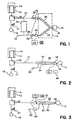
- FIG. 1 there is shown a schematic view of a typical circle patient breathing circuit 10.
- a bellows container 12 encloses a collapsible bellows 14 that provides a positive breath to the patient .
- a ventilator (not shown) forces a controlled amount of a gas into the bellows container 12 to collapse the bellows 14 to force the breathing gas to the patient 16.
- a flexible bag 18 may be used by the clinician so as to manually squeeze the bag and provide that breathing gas to the patient 16 during anesthesia. In either case, there is period that gas is being supplied to the patient, that is, the inspiratory cycle, and a period that the patient is exhaling back into the breathing circuit, that is, the expiratory cycle.
- a bag to ventilator switch 20 allows the clinician to select the mode of delivering that breathing gas, i.e. through use of the powered ventilator or by the manual bagging mode.
- An adjustable pressure limiting valve 21 is also provided that releases gas from the system when a predetermined pressure is exceeded.
- the breathing gas progresses in conduit 22 where it passes through an absorber 24 where the CO 2 from the patient's exhalation is removed and the breathing gas continues through an inlet conduit 26 to the inspiratory limb 28 of the circle patient breathing circuit 10. That gas passes through a check valve 30 to assure the direction of the flow is in the correct direction and a fresh gas inlet 32 is also provided to add the fresh gas to the system and which combines with the gas circulating in conduit 26 to the circle patient breathing circuit 10 to be administered to the patient.
- a patient connection 34 connects to the patient 16 and provides that breathing gas to the patient 16. As the patient exhales, the gas passes through an expiratory limb 36 of the circle patient breathing circuit 10 and passes that exhaled gas through another check valve 38 to be continuously recirculated through the circle patient breathing circuit 10.
- An inspiratory flow sensor 40 is provided to monitor the flow in the inspiratory limb 28 and an expiratory flow sensor 42 likewise monitors the flow in the expiratory limb 36.
- an expiratory flow sensor monitors the flow from the patient and that flow signal is integrated with respect to the time of the expiratory cycle. That integration may be processed by a CPU 43 to arrive at the tidal volume of the gas to the patient 16 and which may be displayed to the clinician at a display 46.
- FIG. 2 there is shown a schematic view of a conventional Bain patient breathing circuit 48.
- the Bain patient breathing circuit 48 comprises some of the same machine components as the circle patient breathing circuit 10 of FIG. 1 and, where applicable, the same numbers have been assigned to those components.
- the difference is in the Bain patient breathing circuit 48 being comprised of a large bore tube 50 that receives the breathing gas from the bellows 14 or the flexible bag 18 for delivery to the patient.
- the fresh gas is provided at a fresh gas inlet 52 and which is then carried in a smaller tubing 54 that is located internal and coaxial to the large bore tube 50 and terminates adjacent the patient connector 56.
- a flow sensor 58 is located at the proximal or patient end of the Bain patient breathing circuit 48 to monitor all of the patients expired gas. If a flow sensor is placed at the distal or machine end of Bain patient breathing circuit 48, it would read high since it would also include the effect of fresh gas that is delivered continuously and therefore would monitor the fresh gas that is provided even during the expiration cycle. That fresh gas has, of course, not been inhaled by the patient so that the flow sensor at the distal or machine end would provide an inaccurate indication of tidal volume to the patient.
- the device adds considerable additional dead space to the overall breathing system and also adds clutter to the patient connector, thereby making facial surgery more difficult.
- the additional dead space is of utmost importance when dealing with pediatric or small infant patients where the flows are considerably small.
- the Mapleson D circuit that is commonly used in patient breathing circuits is very similar to the Bain patient breathing circuit but the small tubing 54 is located external of the large bore tube 50 and runs along that exterior surface and introduces the fresh gas through the patient connector.
- FIG. 3 there is shown a schematic view of a patient breathing circuit having flow sensors located in accordance with the present invention.
- the Bain patient breathing circuit 48 is used as in FIG. 2.
- a fresh gas flow sensor 60 has been positioned in the fresh gas inlet 52 and which thereby monitors the flow of fresh gas to the Bain breathing circuit at all times.
- a further flow sensor 62 is positioned so as to monitor the flow in the large bore tube 50 and which, therefore can monitor the flow from the patient expiration during that cycle.
- both of the flow sensors 60 and 62 are positioned at the distal end of the Bain patient breathing circuit 48.
- the CPU 43 can receive a signal representative of flow of fresh gas to the Bain patient breathing circuit 48 during the patient expiration period and also receive a signal representative of the flow of the gases from the patient at the machine or proximal end of the large bore tube 50.
- the CPU 43 can thus subtract the flow in the fresh gas conduit during that expiration period and from the total flow of gas from the patient during the expiration and arrive at an accurate determination of the flow from the patient, having taken into account, the flow that was introduced during the expiration cycle and which was not inhaled by the patient.
- the information as to the fresh gas flow can be manually obtained from a user input or directly from an electronic mixer.
Landscapes
- Health & Medical Sciences (AREA)
- Emergency Medicine (AREA)
- Pulmonology (AREA)
- Engineering & Computer Science (AREA)
- Anesthesiology (AREA)
- Biomedical Technology (AREA)
- Heart & Thoracic Surgery (AREA)
- Hematology (AREA)
- Life Sciences & Earth Sciences (AREA)
- Animal Behavior & Ethology (AREA)
- General Health & Medical Sciences (AREA)
- Public Health (AREA)
- Veterinary Medicine (AREA)
- Measurement Of The Respiration, Hearing Ability, Form, And Blood Characteristics Of Living Organisms (AREA)
- Measuring And Recording Apparatus For Diagnosis (AREA)
Claims (6)
- System zum Ermitteln des Atemvolumens eines Patienten, der während eines Einatmungstaktes Atemzüge von einer Beatmungsvorrichtung (12 bis 20) erhält, wobei das System die Ausatmung des Patienten während eines Ausatmungstaktes erhält, welches System umfasst:Einen Patientenbeatmungskreis (48) mit einem Hauptversorgungsschlauch (50), der ein distales Ende aufweist, welches so ausgestaltet ist, dass es an eine Beatmungsvorrichtung (12 bis 20) angeschlossen werden kann, sowie ein proximales Ende, das so ausgestaltet ist, dass es an einen Patienten (16) angeschlossen werden kann, um die Beatmungsvorrichtung (12 bis 20) mit dem Patienten (16) zu verbinden, einen Frischgasversorgungsschlauch (54), der so ausgestaltet ist, dass er an eine Frischgasquelle angeschlossen werden kann, um frisches Gas aus der Frischgasquelle zum Patienten (16) zu liefern,einen ersten Durchflusssensor (62), der so ausgestaltet ist, dass er den Gasdurchfluss innerhalb des Hauptversorgungsschlauches (50) ermittelt, einen zweiten Durchflusssensor (60) zum Ermitteln des Durchflusses an Frischgas durch den Schlauch (54) während des Ausatmungstaktes, undeinen Prozessor (43), der so ausgestaltet ist, dass er Signale von den ersten und zweiten Durchflusswächtern (62, 60) erhält,dadurch gekennzeichnet,
dass der Prozessor (43) so ausgestaltet ist, dass er:(a) einen Subtraktionsschritt durchführt, der den Durchfluss an Frischgas während des Ausatmens, der vom zweiten Sensor detektiert wird, vom Durchfluss an während des Ausatmens durch den Hauptversorgungsschlauch (50) fließendem Gas subtrahiert, der vom ersten Sensor detektiert wird, und hierbei einen Wert des Gasdurchflusses während des Ausatmens des Patienten errechnet, um einen Messwert für das vom Patienten ausgeatmete Gasvolumen bereitzustellen, und/oder(b) einen Additionsschritt durchführt, der den Gasdurchfluss im Frischgas-Versorgungsschlauch (54) während eines Einatmungstaktes, der vom zweiten Sensor detektiert wird, zum Gasdurchfluss im Hauptversorgungsschlauch (50) addiert, der vom ersten Sensor (62) während des Einatmungstaktes detektiert wird, und hierbei den Gesamtdurchfluss an Gas zum Patienten während des Einatmungstaktes ermittelt, um einen Messwert des an den Patienten abgegebenen Gasvolumens bereitzustellen. - System nach Anspruch 1,
bei welchem der Prozessor so ausgestaltet ist, dass er den aus dem Subtraktionsschritt (a) hergeleiteten Gasdurchflusswert über eine bekannte Zeitdauer integriert, zum Beispiel über die Ausatmungszeit, um das Gasvolumen, das vom Patienten ausgeatmet wird, zu ermitteln. - System nach Anspruch 1 oder Anspruch 2,
bei welchem der erste Durchflusssensor (62) am distalen Ende des Hauptversorgungsschlauches (50) angeordnet ist. - System nach irgendeinem der Ansprüche 1 bis 3,
bei welchem der Frischgasschlauch (54) ein proximales Ende aufweist, welches das Frischgas am oder nahe beim proximalen Ende des Hauptversorgungsschlauchs (50) an den Patienten abgibt, sowie ein distales Ende, wobei der zweite Durchflusssensor (60) am distalen Ende des Frischgasschlauchs (54) angeordnet ist. - System nach irgendeinem der Ansprüche 1 bis 4,
bei welchem der Patientenbeatmungskreis ein Bain-Beatmungskreis (Bain circuit) ist. - System nach irgendeinem der Ansprüche 1 bis 4,
bei welchem der Patientenbeatmungskreis ein Mapleson D-Kreis (Mapleson D circuit) ist.
Applications Claiming Priority (2)
| Application Number | Priority Date | Filing Date | Title |
|---|---|---|---|
| US938850 | 1986-12-08 | ||
| US08/938,850 US6125848A (en) | 1997-09-26 | 1997-09-26 | Distal volume monitoring |
Publications (3)
| Publication Number | Publication Date |
|---|---|
| EP0904793A2 EP0904793A2 (de) | 1999-03-31 |
| EP0904793A3 EP0904793A3 (de) | 1999-12-08 |
| EP0904793B1 true EP0904793B1 (de) | 2006-04-26 |
Family
ID=25472067
Family Applications (1)
| Application Number | Title | Priority Date | Filing Date |
|---|---|---|---|
| EP98307698A Expired - Lifetime EP0904793B1 (de) | 1997-09-26 | 1998-09-22 | Überwachung von Distalenvolumen |
Country Status (2)
| Country | Link |
|---|---|
| US (1) | US6125848A (de) |
| EP (1) | EP0904793B1 (de) |
Families Citing this family (16)
| Publication number | Priority date | Publication date | Assignee | Title |
|---|---|---|---|---|
| CA2283430C (en) * | 1997-03-19 | 2006-05-23 | Joseph A. Fisher | Elimination of vapour anaesthetics from patients after surgical procedures |
| FR2804030B1 (fr) * | 2000-01-21 | 2003-01-03 | Taema | Appareil d'anesthesie respiratoire a gestion automatique des debits gazeux |
| CA2304292C (en) * | 2000-03-31 | 2009-01-13 | Joseph Fisher | An improved rebreathing circuit to set and stabalize end tidal and arterial pco2 despite varying levels of minute ventilation |
| US7073502B2 (en) | 2003-01-27 | 2006-07-11 | Instrumentarium Corp. | Manual ventilation system including manual bag filling valve |
| JP4684300B2 (ja) | 2005-02-02 | 2011-05-18 | モコン・インコーポレーテッド | 密封シールされた包装における漏洩の大きさの検出及び報告用装置及び方法 |
| WO2006088542A2 (en) | 2005-02-14 | 2006-08-24 | Mocon, Inc. | Detecting and reporting the location of a leak in hermetically sealed packaging |
| US7252014B1 (en) | 2006-04-17 | 2007-08-07 | Mocon, Inc. | Instrument and method for measuring the volume of a hermetically sealed variable volume and pressure conforming container |
| US7654131B2 (en) | 2006-06-14 | 2010-02-02 | Mocon, Inc. | Instrument for accurately measuring mass flow rate of a fluid pumped from a hermetically sealed container |
| AU2006252044B2 (en) * | 2006-12-13 | 2014-04-03 | Colin Dunlop | Method and apparatus for delivering a fluid to a patient |
| CN101468221B (zh) * | 2007-12-29 | 2013-10-23 | 北京谊安医疗系统股份有限公司 | 麻醉吸收回路 |
| CN101301503B (zh) * | 2008-06-26 | 2010-06-02 | 上海力申科学仪器有限公司 | 麻醉机潮气量的自动标定方法 |
| CN101934108B (zh) * | 2009-07-02 | 2013-08-14 | 北京谊安医疗系统股份有限公司 | 用于麻醉机或呼吸机的潮气量检测方法和装置 |
| DE102015015441A1 (de) * | 2015-12-02 | 2017-06-08 | Drägerwerk AG & Co. KGaA | Anästhesiebeatmungsvorrichtung zur automatisierten Beatmung sowie zur Detektion eines Betriebszustandes hinsichtlich der automatisierten Beatmung |
| CN109259766A (zh) * | 2018-11-16 | 2019-01-25 | 培婴(湖北)医学技术有限公司 | 潮气量的监测装置及呼吸机 |
| CN111990999A (zh) * | 2020-09-24 | 2020-11-27 | 苏州大学 | 基于简易单向阀分流气体的潮气量实时监测装置及方法 |
| CN119345542A (zh) * | 2020-12-31 | 2025-01-24 | 深圳迈瑞动物医疗科技股份有限公司 | 呼吸通气方法、装置、麻醉机及计算机可读存储介质 |
Family Cites Families (9)
| Publication number | Priority date | Publication date | Assignee | Title |
|---|---|---|---|---|
| US3856051A (en) * | 1972-02-28 | 1974-12-24 | J Bain | Flexible tube device |
| US3972327A (en) * | 1973-03-22 | 1976-08-03 | Hoffmann-La Roche Inc. | Respirator |
| US3910261A (en) * | 1974-06-11 | 1975-10-07 | Bourns Inc | End-tidal gas analysis apparatus for respirators |
| AU547514B2 (en) * | 1980-09-02 | 1985-10-24 | David Humphrey | Anaesthetic system with waste gas scavenging |
| GB8509413D0 (en) * | 1985-04-12 | 1985-05-15 | Penlon Ltd | Gas flow control apparatus |
| US5107831A (en) * | 1989-06-19 | 1992-04-28 | Bear Medical Systems, Inc. | Ventilator control system using sensed inspiratory flow rate |
| CA2004930C (en) * | 1989-12-08 | 1996-04-02 | John Richard Sikora | Anaesthetic and respirator breathing circuit device |
| US5161525A (en) * | 1990-05-11 | 1992-11-10 | Puritan-Bennett Corporation | System and method for flow triggering of pressure supported ventilation |
| US5315989A (en) * | 1991-12-09 | 1994-05-31 | Boc Health Care, Inc. | Medical ventilator |
-
1997
- 1997-09-26 US US08/938,850 patent/US6125848A/en not_active Expired - Fee Related
-
1998
- 1998-09-22 EP EP98307698A patent/EP0904793B1/de not_active Expired - Lifetime
Also Published As
| Publication number | Publication date |
|---|---|
| EP0904793A2 (de) | 1999-03-31 |
| EP0904793A3 (de) | 1999-12-08 |
| US6125848A (en) | 2000-10-03 |
Similar Documents
| Publication | Publication Date | Title |
|---|---|---|
| EP0904793B1 (de) | Überwachung von Distalenvolumen | |
| US6571792B1 (en) | Smart modular anesthesia respiratory system | |
| CN109069782B (zh) | 一种麻醉机及系统 | |
| JP3955011B2 (ja) | 心拍出量を非侵襲的に測定する装置及び方法 | |
| EP1001824B1 (de) | Zur gasinsufflation in die luftröhre vorgesehenes abgabesystem für beatmungsgerät | |
| EP0923397B1 (de) | Dosiergerät eines spezialgases für eine beatmungsanlage | |
| US6213120B1 (en) | Device and method for determining gas volume and volumetric changes in a ventilator | |
| US4127121A (en) | Oxygen and anesthesia delivery and monitoring device | |
| US7909033B2 (en) | Breathing treatment apparatus | |
| US4502481A (en) | Device for manually ventilating a patient | |
| US6152132A (en) | Inspiratory tube for a ventilator | |
| EP1800707B1 (de) | Beatmungsgerät mit nasalem Auslöser und Gasüberwachungssystem | |
| CN101927050B (zh) | 用于输送患者的呼吸气体的支路单元 | |
| US20110197887A1 (en) | Accessory connection and data synchronication in a ventilator | |
| US20050121033A1 (en) | Respiratory monitoring during gas delivery | |
| JPH11137689A (ja) | ベンチレーター | |
| US8925549B2 (en) | Flow control adapter for performing spirometry and pulmonary function testing | |
| EP0832662B1 (de) | Narkosesysteme | |
| JP2010531685A (ja) | 気道確保システムのためのガス混合装置 | |
| JP2000070370A (ja) | 人工呼吸器 | |
| CN103251410A (zh) | 用于分析呼吸气体的设备、配置和方法 | |
| CN102834136A (zh) | 补偿危重症护理呼吸机中不可测量的吸气流 | |
| EP1409054B1 (de) | Vorrichtung zur isolierung des vorspannungsstorms | |
| JPH0390164A (ja) | 患者の呼吸流量に合わせて回路内流量と回路内圧を制御する人工呼吸器 | |
| JP3020606B2 (ja) | 酸素消費量メーター |
Legal Events
| Date | Code | Title | Description |
|---|---|---|---|
| PUAI | Public reference made under article 153(3) epc to a published international application that has entered the european phase |
Free format text: ORIGINAL CODE: 0009012 |
|
| AK | Designated contracting states |
Kind code of ref document: A2 Designated state(s): ES GB |
|
| AX | Request for extension of the european patent |
Free format text: AL;LT;LV;MK;RO;SI |
|
| RAP1 | Party data changed (applicant data changed or rights of an application transferred) |
Owner name: DATEX-OHMEDA, INC. |
|
| PUAL | Search report despatched |
Free format text: ORIGINAL CODE: 0009013 |
|
| AK | Designated contracting states |
Kind code of ref document: A3 Designated state(s): AT BE CH CY DE DK ES FI FR GB GR IE IT LI LU MC NL PT SE |
|
| AX | Request for extension of the european patent |
Free format text: AL;LT;LV;MK;RO;SI |
|
| RIC1 | Information provided on ipc code assigned before grant |
Free format text: 6A 61M 16/00 A |
|
| 17P | Request for examination filed |
Effective date: 20000608 |
|
| AKX | Designation fees paid |
Free format text: ES GB |
|
| REG | Reference to a national code |
Ref country code: DE Ref legal event code: 8566 |
|
| 17Q | First examination report despatched |
Effective date: 20050127 |
|
| GRAP | Despatch of communication of intention to grant a patent |
Free format text: ORIGINAL CODE: EPIDOSNIGR1 |
|
| GRAS | Grant fee paid |
Free format text: ORIGINAL CODE: EPIDOSNIGR3 |
|
| GRAA | (expected) grant |
Free format text: ORIGINAL CODE: 0009210 |
|
| AK | Designated contracting states |
Kind code of ref document: B1 Designated state(s): ES GB |
|
| REG | Reference to a national code |
Ref country code: GB Ref legal event code: FG4D |
|
| PG25 | Lapsed in a contracting state [announced via postgrant information from national office to epo] |
Ref country code: ES Free format text: LAPSE BECAUSE OF FAILURE TO SUBMIT A TRANSLATION OF THE DESCRIPTION OR TO PAY THE FEE WITHIN THE PRESCRIBED TIME-LIMIT Effective date: 20060806 |
|
| PLBE | No opposition filed within time limit |
Free format text: ORIGINAL CODE: 0009261 |
|
| STAA | Information on the status of an ep patent application or granted ep patent |
Free format text: STATUS: NO OPPOSITION FILED WITHIN TIME LIMIT |
|
| 26N | No opposition filed |
Effective date: 20070129 |
|
| PGFP | Annual fee paid to national office [announced via postgrant information from national office to epo] |
Ref country code: GB Payment date: 20080820 Year of fee payment: 11 |
|
| GBPC | Gb: european patent ceased through non-payment of renewal fee |
Effective date: 20090922 |
|
| PG25 | Lapsed in a contracting state [announced via postgrant information from national office to epo] |
Ref country code: GB Free format text: LAPSE BECAUSE OF NON-PAYMENT OF DUE FEES Effective date: 20090922 |