EP0904695A2 - Automatic breadmaker with plural kneading members - Google Patents
Automatic breadmaker with plural kneading members Download PDFInfo
- Publication number
- EP0904695A2 EP0904695A2 EP99100095A EP99100095A EP0904695A2 EP 0904695 A2 EP0904695 A2 EP 0904695A2 EP 99100095 A EP99100095 A EP 99100095A EP 99100095 A EP99100095 A EP 99100095A EP 0904695 A2 EP0904695 A2 EP 0904695A2
- Authority
- EP
- European Patent Office
- Prior art keywords
- pan
- kneading
- automatic
- breadmaker
- bread
- Prior art date
- Legal status (The legal status is an assumption and is not a legal conclusion. Google has not performed a legal analysis and makes no representation as to the accuracy of the status listed.)
- Withdrawn
Links
Images


Classifications
-
- A—HUMAN NECESSITIES
- A21—BAKING; EDIBLE DOUGHS
- A21C—MACHINES OR EQUIPMENT FOR MAKING OR PROCESSING DOUGHS; HANDLING BAKED ARTICLES MADE FROM DOUGH
- A21C1/00—Mixing or kneading machines for the preparation of dough
- A21C1/02—Mixing or kneading machines for the preparation of dough with vertically-mounted tools; Machines for whipping or beating
-
- A—HUMAN NECESSITIES
- A21—BAKING; EDIBLE DOUGHS
- A21B—BAKERS' OVENS; MACHINES OR EQUIPMENT FOR BAKING
- A21B7/00—Baking plants
- A21B7/005—Baking plants in combination with mixing or kneading devices
-
- A—HUMAN NECESSITIES
- A21—BAKING; EDIBLE DOUGHS
- A21C—MACHINES OR EQUIPMENT FOR MAKING OR PROCESSING DOUGHS; HANDLING BAKED ARTICLES MADE FROM DOUGH
- A21C1/00—Mixing or kneading machines for the preparation of dough
- A21C1/14—Structural elements of mixing or kneading machines; Parts; Accessories
- A21C1/1405—Tools
-
- B—PERFORMING OPERATIONS; TRANSPORTING
- B01—PHYSICAL OR CHEMICAL PROCESSES OR APPARATUS IN GENERAL
- B01F—MIXING, e.g. DISSOLVING, EMULSIFYING OR DISPERSING
- B01F27/00—Mixers with rotary stirring devices in fixed receptacles; Kneaders
- B01F27/05—Stirrers
- B01F27/051—Stirrers characterised by their elements, materials or mechanical properties
- B01F27/054—Deformable stirrers, e.g. deformed by a centrifugal force applied during operation
- B01F27/0543—Deformable stirrers, e.g. deformed by a centrifugal force applied during operation the position of the stirring elements depending on the direction of rotation of the stirrer
Definitions
- This invention is related generally to food apparatus and, more particularly, to breadmakers.
- the dimensional proportions of the loaf made using, e.g., the Asahina et al., Takeuchi and Seo et al. breadmakers are unusual. Such loaves are substantially cubic. A loaf made using the Ojima or Aoyama breadmaker is cylindrical and, therefore, even more unusual -- and more difficult to slice or to toast in a conventional toaster which accommodates slices from a normal bakery loaf.
- the raised top part of the loaf resembles a bowl-like dome rather than the longer top side of a normal bakery loaf. Since a cubic loaf is often placed on one of its four flat sides for slicing, the slice which includes the dome end has a shape quite unlike the end slice of a normal bakery loaf which is substantially flat or only slightly curved. Some prefer not to serve such a dome-shaped slice, especially to guests.
- the bread produced by these prior art breadmakers has an upwardly elongate, cubic or cylindrical appearance because the prior art devices rely on a single rotary vane (as shown in the Ojima patent) or similar structure to mix the bread components and knead the dough.
- Use of a single vane limits the length of the horizontal axis of the bread pan because the vane must span virtually the entire bottom surface of the bread pan to adequately mix the bread components and knead the dough. The result is a loaf of bread which has an unusual shape and does not resemble a bakery loaf.
- Rotary vanes for kneading the dough mix have other disadvantages.
- the vane "imprint" in the loaf end is a small cavity (or “navel” as it is sometimes called) with a hollow passage extending from such cavity.
- the cavity and passage are exposed to view.
- a normal bakery loaf is free of such cavity and passage.
- Another object of this invention is to provide an automatic breadmaker capable of baking a loaf of bread having a configuration like that of a normal bakery loaf.
- Another object of this invention is to provide an automatic breadmaker capable of baking a loaf of bread which is longer than it is wide.
- Still another object of this invention is to provide an automatic breadmaker capable of baking a loaf of bread which is free of a bowl-like dome on its end.
- Another object of this invention is to provide an automatic breadmaker capable of baking a loaf of bread which is free of a small cavity in the loaf end.
- Yet another object of this invention is to provide an automatic breadmaker capable of baking a loaf of bread providing slices that are free of a keyhole-shaped opening. How these and other objects are accomplished will become apparent from the following detailed description and from the drawing.
- the invention involves an automatic breadmaker having a base and drive means including a motor secured to such base.
- a drive linkage extends from the motor and terminates at the chamber in a pair of drive members, each of which has a drive shaft linked to it.
- the new breadmaker also has an oven chamber and a pan in the chamber.
- the pan is a horizontally-configured "wide-loaf" pan with a spaced pair of paddle-like kneading members in it.
- the kneading members are linked to and powered by the drive means for ingredient mixing and dough kneading.
- the new breadmaker facilitates automatic preparation of a loaf of normal configuration having a curved "crown-like" risen topside extending along its length and otherwise having an appearance closely resembling that of a commercially-baked loaf.
- the pan has a bottom which is longer than it is wide and the pair of kneading members are spaced along the length of the pan and rotate simultaneously in a plane generally parallel to the pan bottom.
- the kneading members and pan are cooperatively sized so that dough in the pan will be reached by one or both of the kneading members.
- each kneading member has a grip member embodied as a hub which slips over and engages a drive shaft.
- the grip member facilitates easy attachment of a kneading member to its shaft and subsequent removal of such kneading member for washing following baking.
- each hub has a lower end and a blade pivotably secured along such lower end.
- the blade pivots between an upright kneading position and a collapsed non-kneading position along the pan bottom. Whether or not the blade is upright or collapsed is a function of the rotation direction in which the kneading member is driven.
- the pan bottom has recessed portions, each of which receives one of the kneading members. Such recessed portions are of sufficient depth to fully receive the collapsed blades.
- the pan bottom has a spaced, parallel pair of drive shafts through it and a pair of drive members below the pan.
- Each kneading member is linked to a separate respective drive shaft and, in turn, each shaft is coupled to a respective driving member, both of which are driven by the motor.
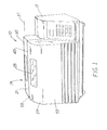
- FIGURE 1 is a perspective view of the new breadmaker.
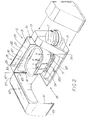
- FIGURE 2 is a perspective view of the breadmaker with the door open and the compartment cover removed.
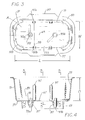
- FIGURE 3 is a top plan view of the new pan used with the breadmaker of FIGURES 1 and 2.
- FIGURE 4 is a cross-section side elevation view of the pan of FIGURE 3.
- FIGURE 5 is a cross-section view of the pan of FIGURE 4 taken along any one of the viewing planes 5-5 thereof.
- FIGURE 6 is a cross-section side elevation view of a second embodiment of the pan of FIGURE 3.
- FIGURE 7 is a representative top plan view of the floor of the new breadmaker.
- FIGURE 8 is a perspective view of the pan of FIGURES 3, 4 and 5 shown in conjunction with a loaf of bread.
- FIGURE 9 is an underside perspective view of the arrangement for driving the kneading members of the breadmaker.
- FIGURE 10 is a perspective exploded view of a kneading member.
- FIGURE 11 is a section view of the kneading member taken generally along the plane 11-11 of FIGURE 10.
- FIGURE 12 is a section view of the kneading member taken generally along the plane 12-12 of FIGURE 10.
- the term “length” means a dimension measured generally left-right as viewed in FIGURES 1, 2, 3 and 4.
- the term “width” means a dimension measured generally front-rear as viewed in FIGURE 1 or measured generally up-down as viewed in FIGURE 3.
- the terms “height” or “depth” means a dimension measured generally up-down as in FIGURES 1, 2 and 4.
- the new automatic breadmaker 10 has a base or floor 11 and a compartment 13 atop the floor. Such compartment 13 encloses a controller 15 and a reversible electric motor 17.
- the controller 15 executes the operating cycle of the breadmaker 10 and as described in more detail below, the motor 17 powers kneading members which mix ingredients to make bread dough.
- An oven chamber 19 is atop the floor 11, abuts the compartment 13 and is formed by the floor 11, a wall member 21 and an access door 23 having a window 25 allowing the user to view kneading and baking operations.
- a pan 27 for receiving ingredients mixed to make bread dough is mounted in the chamber 19.
- the wall member 21 has a rear portion 29, a top portion 31 and lateral side portions 33, all of which are fixed, i.e., non-movable with respect to one another and to the floor 11.
- the surface 35 of the top portion 31 is at a first level 37 above the breadmaker floor 11 and the portions 31, 33 define a flat face which is substantially perpendicular.
- the wall member 21 also has a vertical lateral edge 41 and a horizontal top edge 43, the latter located substantially directly above the pan 27 and extending along the pan length.
- the access door 23 is hinged to the wall member 21 along the front lateral edge 41 of the wall member 21 and along a rear lateral edge 45 of the door 23 and is pivotable laterally about a substantially vertical axis 47.
- the access door 23 swings in a substantially horizontal direction and creates a front opening 49 extending substantially to the floor 11, to the region above the pan and to the side portions 33.
- the door 23 itself has a front surface 53 and a top surface 55, both of which are attractively curvilinear. There are also substantially flat first and second side surfaces 57, 59, respectively, the former having a substantially vertical rear edge 45. At least major portions of the top surface 55 and the first side surface 57 extend rearwardly from the front surface 53.
- the door 23 swings laterally for front opening without any door movement above the first level 37 and the resulting opening 49 extends substantially to the oven floor 11.
- the portions 55, 57, 59 also define a flat face 61 which is substantially perpendicular and which abuts the face 39 of the wall member 21 when the door 23 is closed for baking.
- the access door 23 When the access door 23 is closed, it extends upwardly from along the oven floor 11 and curves rearwardly to a position directly above the pan 27. That is, the top edge 63 of the door 23 abuts the top edge 43 of the wall member 21 directly above the pan 27.
- the breadmaker 10 has a very generous mouth area, open at the top as well as at the front and sides, so that insertion and removal of the pan 27 is further facilitated.
- a laterally-swinging door 23 has advantages over a top-hinged door (a door hinged along its top edge), especially where a breadmaker occupies a place on a kitchen counter beneath cupboards, as is frequently the case. Such a door 23 swings substantially horizontally and permits multi-directional access to the oven chamber 19 with the door 23 away from the front of the breadmaker 10. Counter-to-cupboard spacing can prevent a top-hinged door from being fully opened and/or from staying open.
- the laterally-swinging door 23 also has advantages over a bottom-hinged door since when open, the latter protrudes outward toward the user and may impair easy access to the oven chamber.
- FIGURE 2 It is apparent from FIGURE 2 that the oven floor 11 and the access door 23 are each longer than the pan 27.
- Such configuration accommodates "wide-side” insertion of the pan 27 into the chamber 19 and minimizes the height of the breadmaker 10.
- Wide-side means that the pan 27 can be inserted into the chamber 19 while holding the pan so that as shown in FIGURE 3, its long axis 65 is generally parallel to the rear portion 29 of the wall member 21. There is no need to twist or turn the pan 27 during pan placement and removal.
- the new pan 27 has a bottom 67 supported atop a "foot-like" downwardly-extending rim 69. When the pan 27 is in place in the chamber 19, such rim 69 rests on the oven floor 11.
- the pan 27 has first and second end panels 71 and 73, respectively, and first and second side panels 75 and 77, respectively.
- the panels 71, 73, 75 and 77 are substantially flat and extend upwardly from the bottom 67 at an angle thereto which is slightly greater than 90°.
- the pan 27 is thereby said to have "draft" so that the baked loaf can be easily removed therefrom by inverting the pan 27 .
- the junctions 79 of the panels 71, 73, 75, 77 with the bottom 67 and the junctions 81 of the panels 71, 73, 75, 77 with one another are slightly curved and serve to give a shape to the finished loaf which closely resembles that of a normal bakery loaf made in a commercial bakery.
- the top of the pan 27 is bounded by an outwardly-projecting lip 83 and a handle 85 juts from the lip 83 above each of the side panels 75 and 77. While the pan 27 may be grasped by the lip 83 anywhere around its perimeter, the handles 85 permit a more positive grasp which is of benefit when handling a hot pan 27 with insulated mitts, pads or the like.
- the bottom 67 has a pair of bosses 87 spaced along the length of the pan 27.
- Each boss 87 has a shaft aperture 89 formed in it and a bearing 91 is mounted in each aperture 89 to receive a shaft 93 with slight sliding clearance.
- Such shafts 93 are linked to the motor 17, extend through the pan bottom 67 and drive the kneading members 95a, 95b.
- the interior of the pan 27 includes a plurality of spaced-apart mixing ridges 97 extending generally between the bottom 67 and the lip 83.
- there are four ridges 97 i.e., a pair of ridges 97 for each kneading member 95.
- Each ridge 97 is linear in an up-down direction and has a generally semi-circular cross-sectional shape.
- each opposed pair of ridges e.g., ridges 97a and 97b as in FIGURE 3
- the pan 27 has a length L, a width W, an inside base area A (the area circumscribed by the overlay heavy dashed line 103) and a depth D.
- the ratio of length L to width W is greater than 1.5 and, most preferably, such ratio is greater than 1.8.
- the ratio of depth D to inside bottom area A is preferably less than about 0.1 and, most preferably, is less than about 0.08. (It is noted that D and A are linear and area measurements, respectively. The ratios use numerical values without regard to units of measure.)
- another feature of the new pan 27 is that right cross-sectional configurations of the pan 27, i.e., the pan size and shape as viewed in cross-section at planes 5-5 at right angles to the long axis 65 of the pan 27 and at spaced locations along the pan length, are substantially constant. This feature also contributes to the fact that the loaf produced by the new breadmaker 10 has the appearance of a normal bakery loaf.
- a second embodiment of the pan 27 includes a pan bottom 105 having a pair of recessed portions 107, each receiving one of the kneading members 95 described below.
- each recessed portion 107 is of sufficient depth to fully receive the collapsed blade 109 of the kneading member 95. That is, when a blade 109 is folded flat as shown in dashed outline in FIGURE 12, such blade 109 is "nested" in a recessed portion 107.
- such floor 11 has a floor length FL and a floor width FW.
- the preferred ratio of floor length FL to floor width FW is at least about 1.5 and most preferably, such ratio is at least about 1.8.
- the breadmaker 10 and its pan 27 produce a loaf of bread 111 in the configuration of a normal bakery loaf. That is, the loaf 111 has substantially flat ends and sides and a risen topside 113 extending along its length. As is characteristic of a normal bakery loaf, the loaf produced by the breadmaker is "crowned" or curved in two mutually-perpendicular planes as represented by the arrows 115 and 117.
- the motor is coupled to means 119 for driving such members 95 and has a smaller-diameter driving pulley 121 attached to and rotating with the motor shaft.
- Such pulley 121 is linked by a belt 123 to a larger-diameter driven pulley 125 which rotates at a speed well below that of the pulley 121.
- a first intermediate-diameter gear 127 is mounted on and concentric with the pulley 125 and, of course, rotates at the same speed as the pulley 125.
- the first gear 127 engages a second gear 129 which is also of intermediate diameter equal to that of the first gear 127. From the foregoing, it is apparent that for either direction of motor rotation, the gears 127, 129 rotate in opposite directions at the same speed.
- the shaft 93a driving one of the kneading members 95a is concentric with the gear 129 and the shaft 93b driving the other kneading member 95b is concentric with the pulley 125 and gear 127.
- the shafts 93a, 93b are substantially parallel to one another and both shafts 93 rotate at the same speed which, of course, is much lower than the shaft speed of the motor 17.
- Each kneading member 95 has a hub 135 with an opening 137 therethrough sized and shaped to fit its respective drive shaft 93 with slight sliding clearance.
- the opening 137 may be in the shape of the letter D or may have any other torque-transmitting shape, e.g., square or hexagon.
- the hub 135 includes a grip member 139 to facilitate finger grasping and attachment of the kneading member 95 after the pan 27 is placed in the breadmaker 10 reparatory to ingredient mixing, dough kneading and baking.
- Each kneading member 95 includes a lower arm 141 extending radially outward from the hub 135 and having a kneading blade 109 pivotably pinned to it.
- the arm 141 has a pair of radially-spaced tube-like portions 143 between which is received the portion 145 of the blade 109.
- the portions 143 and 145 are coupled together by a pin (not shown).
- the arm 141 also has an abutment member 147 supporting the blade 109 at its upright position.
- its blade 109 stands upright for mixing or kneading (and is supported there by the abutment member 147) or collapses by folding down for baking.
- the kneading members 95a, 95b are "mirror images" of one another so that the blades 109 of both are simultaneously upright or collapsed, notwithstanding that such kneading members 95a, 95b are being driven in opposite directions.
- the arm 14 has an edge surface 149 angled downward toward the pan bottom 67 and outward away from the portions 143, 145.
- edge surface 149 angled downward toward the pan bottom 67 and outward away from the portions 143, 145.
- the member 95 is rotated in a direction which collapses the blade 109 as shown in dashed outline in FIGURE 12, such surface 149 is of some help in urging dough ingredients, i.e., flour or the like, up away from the pan bottom 67. Better ingredient mixing results.
- the kneading members 95a, 95b are spaced along the length of the pan 27 so that dough in the pan 27 will be reached by one or both of such members 95a, 95b.
- the pan 27 is placed (by "wide-side" insertion) into the oven chamber 19 and placement is so that the bottom support rim 69 of the pan 27 is between a pair of retention barriers 151 projecting upward from the floor 11.
- the barriers 151 and the support rim 69 are generally conformably shaped to one another so that the pan 27 is prevented by the barriers 151 from moving a significant distance in any direction.
- a holding latch 153 is mounted on the floor 11 and has a tongue that projects into a slot in the pan rim 69.
- the latch 153 is spring-biased toward the rim 69 for pan holding during mixing and baking and is released by finger pressure at the conclusion of baking.
- the kneading members 95a, 95b are mounted on their respective shafts 93a, 93b and the ingredients then added to the pan 27.
- the operating cycle is initiated and the motor 17 is operated in what is arbitrarily identified as the first or forward direction. So operated, the kneading members 95a and 95b counter-revolve, i.e., they are driven clockwise and counterclockwise, respectively, for several minutes to mix ingredients. During that time, the blades 109 are upright.
- the motor 17 is operated in the second or reverse direction for a time during which the kneading members 95a, 95b also counter-revolve and the blades 109 are collapsed. It has been found that brief reversal tends to pick up unmixed flour from the region 155 of the pan 27 that would not otherwise be properly mixed. Thereafter, the motor 17 is again operated in the forward direction and, finally, is operated in the reverse direction for a few seconds to collapse the blades 109 prior to baking.
- the door 23 is opened horizontally and the pan 27 removed in the same manner in which it was placed in the chamber 19, i.e., by "wide side” removal.
- the resulting loaf 111 is of normal bakery loaf configuration and has a risen topside 113 extending along its length.
Landscapes
- Life Sciences & Earth Sciences (AREA)
- Engineering & Computer Science (AREA)
- Food Science & Technology (AREA)
- Chemical & Material Sciences (AREA)
- Chemical Kinetics & Catalysis (AREA)
- Baking, Grill, Roasting (AREA)
- Food-Manufacturing Devices (AREA)
- Bakery Products And Manufacturing Methods Therefor (AREA)
- Manufacturing And Processing Devices For Dough (AREA)
Abstract
Description
- This invention is related generally to food apparatus and, more particularly, to breadmakers.
- Automatic breadmakers for home use are becoming increasingly popular, in part because the user is able to prepare specialty and custom loaves of bread of a type not available or not readily available at commercial outlets. Another reason for the popularity of such breadmakers is that bread can be consumed when warm, i.e., immediately at the conclusion of baking. Warm, freshly baked bread has a unique aroma and texture that adds to dining pleasure.
- There are a number of examples of automatic breadmakers in the patent literature. U.S. Patent Nos. 4,776,265 (Ojima); 4,836,683 (Aoyama); 4,870,896 (Asahina et al.) and 4,977,822 (Seo et al.) are but a few.
- Despite the growing popularity of automatic breadmakers, their containers produce a loaf of bread which only modestly resembles the size, shape and appearance of a normal bakery loaf. For example, the breadmakers shown in the Asahina et al. and Seo et al. patents have upright rectangular "can-like" containers. Such breadmakers produce a loaf of bread which, in cross-section along a plane normal to the upright long axis of the loaf, is square or substantially so.
- The breadmaker shown in U.S. Patent No. 4,234,605 (Takeuchi) has a pair of such can-like containers connected to one another. But whether used singly or in pairs, the appearance of the loaf is as described above.
- Further, the dimensional proportions of the loaf made using, e.g., the Asahina et al., Takeuchi and Seo et al. breadmakers are unusual. Such loaves are substantially cubic. A loaf made using the Ojima or Aoyama breadmaker is cylindrical and, therefore, even more unusual -- and more difficult to slice or to toast in a conventional toaster which accommodates slices from a normal bakery loaf.
- And when the bread rises in the prior art breadmaker containers noted above, the raised top part of the loaf resembles a bowl-like dome rather than the longer top side of a normal bakery loaf. Since a cubic loaf is often placed on one of its four flat sides for slicing, the slice which includes the dome end has a shape quite unlike the end slice of a normal bakery loaf which is substantially flat or only slightly curved. Some prefer not to serve such a dome-shaped slice, especially to guests.
- The bread produced by these prior art breadmakers has an upwardly elongate, cubic or cylindrical appearance because the prior art devices rely on a single rotary vane (as shown in the Ojima patent) or similar structure to mix the bread components and knead the dough. Use of a single vane limits the length of the horizontal axis of the bread pan because the vane must span virtually the entire bottom surface of the bread pan to adequately mix the bread components and knead the dough. The result is a loaf of bread which has an unusual shape and does not resemble a bakery loaf.
- Rotary vanes for kneading the dough mix have other disadvantages. When baking is complete, the vane "imprint" in the loaf end is a small cavity (or "navel" as it is sometimes called) with a hollow passage extending from such cavity. When the loaf is laid on a side for slicing, the cavity and passage are exposed to view. A normal bakery loaf is free of such cavity and passage.
- Of even greater concern to users of known breadmakers is the fact that at least the first slice from that end of the loaf in contact with the vane has a keyhole-shaped opening through it. Quite aside from aesthetic considerations, a slice of bread with a substantial opening through it would be considered by most to be unsuitable for making sandwiches.
- Known automatic breadmakers lack a horizontally-configured pan and are incapable of mixing and kneading the ingredients in such a pan. An improved breadmaker having such a pan, offering features permitting proper ingredient mixing in such a pan and producing a loaf of bread having a configuration like that of a normal bakery loaf would be an important advance in the art.
- It is an object of this invention to provide an automatic breadmaker overcoming problems in the art, including those mentioned above.
- Another object of this invention is to provide an automatic breadmaker capable of baking a loaf of bread having a configuration like that of a normal bakery loaf.
- Another object of this invention is to provide an automatic breadmaker capable of baking a loaf of bread which is longer than it is wide.
- Still another object of this invention is to provide an automatic breadmaker capable of baking a loaf of bread which is free of a bowl-like dome on its end.
- Another object of this invention is to provide an automatic breadmaker capable of baking a loaf of bread which is free of a small cavity in the loaf end.
- Yet another object of this invention is to provide an automatic breadmaker capable of baking a loaf of bread providing slices that are free of a keyhole-shaped opening. How these and other objects are accomplished will become apparent from the following detailed description and from the drawing.
- The invention involves an automatic breadmaker having a base and drive means including a motor secured to such base. A drive linkage extends from the motor and terminates at the chamber in a pair of drive members, each of which has a drive shaft linked to it. The new breadmaker also has an oven chamber and a pan in the chamber.
- The pan is a horizontally-configured "wide-loaf" pan with a spaced pair of paddle-like kneading members in it. The kneading members are linked to and powered by the drive means for ingredient mixing and dough kneading. The new breadmaker facilitates automatic preparation of a loaf of normal configuration having a curved "crown-like" risen topside extending along its length and otherwise having an appearance closely resembling that of a commercially-baked loaf.
- In another aspect of the invention, the pan has a bottom which is longer than it is wide and the pair of kneading members are spaced along the length of the pan and rotate simultaneously in a plane generally parallel to the pan bottom. The kneading members and pan are cooperatively sized so that dough in the pan will be reached by one or both of the kneading members.
- In a specific embodiment, each kneading member has a grip member embodied as a hub which slips over and engages a drive shaft. The grip member facilitates easy attachment of a kneading member to its shaft and subsequent removal of such kneading member for washing following baking.
- Preferably, each hub has a lower end and a blade pivotably secured along such lower end. The blade pivots between an upright kneading position and a collapsed non-kneading position along the pan bottom. Whether or not the blade is upright or collapsed is a function of the rotation direction in which the kneading member is driven. In an alternate embodiment, the pan bottom has recessed portions, each of which receives one of the kneading members. Such recessed portions are of sufficient depth to fully receive the collapsed blades.
- In another aspect of the invention, the pan bottom has a spaced, parallel pair of drive shafts through it and a pair of drive members below the pan. Each kneading member is linked to a separate respective drive shaft and, in turn, each shaft is coupled to a respective driving member, both of which are driven by the motor.
- Further details of the invention are set forth in the following detailed description and in the drawing.
- FIGURE 1 is a perspective view of the new breadmaker.
- FIGURE 2 is a perspective view of the breadmaker with the door open and the compartment cover removed.
- FIGURE 3 is a top plan view of the new pan used with the breadmaker of FIGURES 1 and 2.
- FIGURE 4 is a cross-section side elevation view of the pan of FIGURE 3.
- FIGURE 5 is a cross-section view of the pan of FIGURE 4 taken along any one of the viewing planes 5-5 thereof.
- FIGURE 6 is a cross-section side elevation view of a second embodiment of the pan of FIGURE 3.
- FIGURE 7 is a representative top plan view of the floor of the new breadmaker.
- FIGURE 8 is a perspective view of the pan of FIGURES 3, 4 and 5 shown in conjunction with a loaf of bread.
- FIGURE 9 is an underside perspective view of the arrangement for driving the kneading members of the breadmaker.
- FIGURE 10 is a perspective exploded view of a kneading member.
- FIGURE 11 is a section view of the kneading member taken generally along the plane 11-11 of FIGURE 10.
- FIGURE 12 is a section view of the kneading member taken generally along the plane 12-12 of FIGURE 10.
- In this specification, the term "length" means a dimension measured generally left-right as viewed in FIGURES 1, 2, 3 and 4. The term "width" means a dimension measured generally front-rear as viewed in FIGURE 1 or measured generally up-down as viewed in FIGURE 3. The terms "height" or "depth" means a dimension measured generally up-down as in FIGURES 1, 2 and 4.
- Referring to FIGURES 1 and 2, the new
automatic breadmaker 10 has a base orfloor 11 and acompartment 13 atop the floor.Such compartment 13 encloses acontroller 15 and a reversible electric motor 17. Thecontroller 15 executes the operating cycle of thebreadmaker 10 and as described in more detail below, the motor 17 powers kneading members which mix ingredients to make bread dough. - An
oven chamber 19 is atop thefloor 11, abuts thecompartment 13 and is formed by thefloor 11, awall member 21 and anaccess door 23 having awindow 25 allowing the user to view kneading and baking operations. Apan 27 for receiving ingredients mixed to make bread dough is mounted in thechamber 19. - The
wall member 21 has arear portion 29, atop portion 31 andlateral side portions 33, all of which are fixed, i.e., non-movable with respect to one another and to thefloor 11. Thesurface 35 of thetop portion 31 is at a first level 37 above thebreadmaker floor 11 and theportions - The
wall member 21 also has a verticallateral edge 41 and a horizontaltop edge 43, the latter located substantially directly above thepan 27 and extending along the pan length. In a highly preferred embodiment, theaccess door 23 is hinged to thewall member 21 along the frontlateral edge 41 of thewall member 21 and along a rearlateral edge 45 of thedoor 23 and is pivotable laterally about a substantiallyvertical axis 47. Thus, theaccess door 23 swings in a substantially horizontal direction and creates a front opening 49 extending substantially to thefloor 11, to the region above the pan and to theside portions 33. - The
door 23 itself has afront surface 53 and atop surface 55, both of which are attractively curvilinear. There are also substantially flat first and second side surfaces 57, 59, respectively, the former having a substantially verticalrear edge 45. At least major portions of thetop surface 55 and thefirst side surface 57 extend rearwardly from thefront surface 53. Thedoor 23 swings laterally for front opening without any door movement above the first level 37 and the resulting opening 49 extends substantially to theoven floor 11. - The
portions flat face 61 which is substantially perpendicular and which abuts the face 39 of thewall member 21 when thedoor 23 is closed for baking. When theaccess door 23 is closed, it extends upwardly from along theoven floor 11 and curves rearwardly to a position directly above thepan 27. That is, thetop edge 63 of thedoor 23 abuts thetop edge 43 of thewall member 21 directly above thepan 27. When thedoor 23 is open, thebreadmaker 10 has a very generous mouth area, open at the top as well as at the front and sides, so that insertion and removal of thepan 27 is further facilitated. - A laterally-swinging
door 23 has advantages over a top-hinged door (a door hinged along its top edge), especially where a breadmaker occupies a place on a kitchen counter beneath cupboards, as is frequently the case. Such adoor 23 swings substantially horizontally and permits multi-directional access to theoven chamber 19 with thedoor 23 away from the front of thebreadmaker 10. Counter-to-cupboard spacing can prevent a top-hinged door from being fully opened and/or from staying open. The laterally-swingingdoor 23 also has advantages over a bottom-hinged door since when open, the latter protrudes outward toward the user and may impair easy access to the oven chamber. - It is apparent from FIGURE 2 that the
oven floor 11 and theaccess door 23 are each longer than thepan 27. Such configuration accommodates "wide-side" insertion of thepan 27 into thechamber 19 and minimizes the height of thebreadmaker 10. ("Wide-side" insertion means that thepan 27 can be inserted into thechamber 19 while holding the pan so that as shown in FIGURE 3, itslong axis 65 is generally parallel to therear portion 29 of thewall member 21. There is no need to twist or turn thepan 27 during pan placement and removal.) - Referring now to FIGURES 1, 3, 4 and 5, features of the
new breadmaker pan 27 will now be described. Thenew pan 27 has a bottom 67 supported atop a "foot-like" downwardly-extendingrim 69. When thepan 27 is in place in thechamber 19,such rim 69 rests on theoven floor 11. - The
pan 27 has first andsecond end panels second side panels panels pan 27 is thereby said to have "draft" so that the baked loaf can be easily removed therefrom by inverting thepan 27 . Thejunctions 79 of thepanels junctions 81 of thepanels - The top of the
pan 27 is bounded by an outwardly-projectinglip 83 and ahandle 85 juts from thelip 83 above each of theside panels pan 27 may be grasped by thelip 83 anywhere around its perimeter, thehandles 85 permit a more positive grasp which is of benefit when handling ahot pan 27 with insulated mitts, pads or the like. - The bottom 67 has a pair of
bosses 87 spaced along the length of thepan 27. Eachboss 87 has ashaft aperture 89 formed in it and abearing 91 is mounted in eachaperture 89 to receive a shaft 93 with slight sliding clearance. Such shafts 93 are linked to the motor 17, extend through the pan bottom 67 and drive the kneadingmembers 95a, 95b. - The interior of the
pan 27 includes a plurality of spaced-apart mixingridges 97 extending generally between the bottom 67 and thelip 83. In a highly preferred embodiment, there are fourridges 97, i.e., a pair ofridges 97 for each kneadingmember 95. Eachridge 97 is linear in an up-down direction and has a generally semi-circular cross-sectional shape. Preferably, each opposed pair of ridges, e.g.,ridges 97a and 97b as in FIGURE 3, are on anaxis 99 spaced slightly from thecenter axis 101 of the adjacent shaft 93. With kneadingmembers 95 configured as described below,such members 95 will "clear" theridges 97 when folded flat for baking at the conclusion of dough kneading. - It has been found that when the
pan 27 is configured to produce a one- or one-and-one-half pound loaf of bread configured like a normal bakery loaf, the preferred number and placement of theridges 97 is as described above.Such ridges 97 tend to keep the ball of bread dough centered in thepan 27 and such ball is less likely to undesirably "spin." And dough ingredients, e.g., flour, scour better from thecurved pan junctions 81. - In another aspect of the invention, the
pan 27 has a length L, a width W, an inside base area A (the area circumscribed by the overlay heavy dashed line 103) and a depth D. In a preferred embodiment, the ratio of length L to width W is greater than 1.5 and, most preferably, such ratio is greater than 1.8. Further, the ratio of depth D to inside bottom area A is preferably less than about 0.1 and, most preferably, is less than about 0.08. (It is noted that D and A are linear and area measurements, respectively. The ratios use numerical values without regard to units of measure.) - Referring particularly to FIGURES 4 and 5, another feature of the
new pan 27 is that right cross-sectional configurations of thepan 27, i.e., the pan size and shape as viewed in cross-section at planes 5-5 at right angles to thelong axis 65 of thepan 27 and at spaced locations along the pan length, are substantially constant. This feature also contributes to the fact that the loaf produced by thenew breadmaker 10 has the appearance of a normal bakery loaf. - Referring also to FIGURES 6 and 12, a second embodiment of the
pan 27 includes apan bottom 105 having a pair of recessedportions 107, each receiving one of the kneadingmembers 95 described below. Preferably, each recessedportion 107 is of sufficient depth to fully receive thecollapsed blade 109 of the kneadingmember 95. That is, when ablade 109 is folded flat as shown in dashed outline in FIGURE 12,such blade 109 is "nested" in a recessedportion 107. - Considering the
oven floor 11 shown in FIGURES 1 and 7,such floor 11 has a floor length FL and a floor width FW. The preferred ratio of floor length FL to floor width FW is at least about 1.5 and most preferably, such ratio is at least about 1.8. - From the foregoing and referring also to FIGURE 8, it will be appreciated that the
breadmaker 10 and itspan 27 produce a loaf ofbread 111 in the configuration of a normal bakery loaf. That is, theloaf 111 has substantially flat ends and sides and a risen topside 113 extending along its length. As is characteristic of a normal bakery loaf, the loaf produced by the breadmaker is "crowned" or curved in two mutually-perpendicular planes as represented by thearrows - Referring now to FIGURES 3, 4, 9, 10, 11 and 12 aspects of the kneading
members 95 and howsuch members 95 are powered will now be described. The motor is coupled to means 119 for drivingsuch members 95 and has a smaller-diameter driving pulley 121 attached to and rotating with the motor shaft.Such pulley 121 is linked by abelt 123 to a larger-diameter drivenpulley 125 which rotates at a speed well below that of thepulley 121. - A first intermediate-
diameter gear 127 is mounted on and concentric with thepulley 125 and, of course, rotates at the same speed as thepulley 125. Thefirst gear 127 engages asecond gear 129 which is also of intermediate diameter equal to that of thefirst gear 127. From the foregoing, it is apparent that for either direction of motor rotation, thegears - The
shaft 93a driving one of the kneadingmembers 95a is concentric with thegear 129 and the shaft 93b driving the other kneading member 95b is concentric with thepulley 125 andgear 127. Theshafts 93a, 93b are substantially parallel to one another and both shafts 93 rotate at the same speed which, of course, is much lower than the shaft speed of the motor 17. - Each kneading
member 95 has ahub 135 with anopening 137 therethrough sized and shaped to fit its respective drive shaft 93 with slight sliding clearance. Theopening 137 may be in the shape of the letter D or may have any other torque-transmitting shape, e.g., square or hexagon. - The
hub 135 includes agrip member 139 to facilitate finger grasping and attachment of the kneadingmember 95 after thepan 27 is placed in thebreadmaker 10 reparatory to ingredient mixing, dough kneading and baking. Each kneadingmember 95 includes alower arm 141 extending radially outward from thehub 135 and having akneading blade 109 pivotably pinned to it. Specifically, thearm 141 has a pair of radially-spaced tube-like portions 143 between which is received theportion 145 of theblade 109. Theportions - The
arm 141 also has anabutment member 147 supporting theblade 109 at its upright position. Depending upon the direction in which a kneadingmember 95 is being driven, itsblade 109 stands upright for mixing or kneading (and is supported there by the abutment member 147) or collapses by folding down for baking. (From the foregoing, it is apparent that the kneadingmembers 95a, 95b are "mirror images" of one another so that theblades 109 of both are simultaneously upright or collapsed, notwithstanding thatsuch kneading members 95a, 95b are being driven in opposite directions.) - The arm 14 has an
edge surface 149 angled downward toward the pan bottom 67 and outward away from theportions member 95 is rotated in a direction which collapses theblade 109 as shown in dashed outline in FIGURE 12,such surface 149 is of some help in urging dough ingredients, i.e., flour or the like, up away from thepan bottom 67. Better ingredient mixing results. Further, the kneadingmembers 95a, 95b are spaced along the length of thepan 27 so that dough in thepan 27 will be reached by one or both ofsuch members 95a, 95b. - In use, the
pan 27 is placed (by "wide-side" insertion) into theoven chamber 19 and placement is so that the bottom support rim 69 of thepan 27 is between a pair ofretention barriers 151 projecting upward from thefloor 11. Thebarriers 151 and thesupport rim 69 are generally conformably shaped to one another so that thepan 27 is prevented by thebarriers 151 from moving a significant distance in any direction. - A holding
latch 153 is mounted on thefloor 11 and has a tongue that projects into a slot in thepan rim 69. Thelatch 153 is spring-biased toward therim 69 for pan holding during mixing and baking and is released by finger pressure at the conclusion of baking. The kneadingmembers 95a, 95b are mounted on theirrespective shafts 93a, 93b and the ingredients then added to thepan 27. - Considering FIGURE 3 particularly, the operating cycle is initiated and the motor 17 is operated in what is arbitrarily identified as the first or forward direction. So operated, the kneading
members 95a and 95b counter-revolve, i.e., they are driven clockwise and counterclockwise, respectively, for several minutes to mix ingredients. During that time, theblades 109 are upright. - Next, the motor 17 is operated in the second or reverse direction for a time during which the
kneading members 95a, 95b also counter-revolve and theblades 109 are collapsed. It has been found that brief reversal tends to pick up unmixed flour from theregion 155 of thepan 27 that would not otherwise be properly mixed. Thereafter, the motor 17 is again operated in the forward direction and, finally, is operated in the reverse direction for a few seconds to collapse theblades 109 prior to baking. - There are advantages to using
kneading members 95a, 95b which counter-revolve irrespective of the direction of motor rotation. One is that while the motor 17 is rotating in the forward direction and theblades 109 are upright, the dough ball tends to stay centered in thepan 27 between themembers 95a, 95b. Another is that when the motor 17 is rotated in the reverse direction and theblades 109 are collapsed, loose flour in theregion 155 is better incorporated into the dough ball. - After baking is complete, the
door 23 is opened horizontally and thepan 27 removed in the same manner in which it was placed in thechamber 19, i.e., by "wide side" removal. As shown in FIGURE 8, the resultingloaf 111 is of normal bakery loaf configuration and has a risen topside 113 extending along its length. - While the principles of this invention have been described in connection with specific embodiments, it should be understood clearly that these descriptions are made only by way of example and are not intended to limit the scope of the invention.
- The features disclosed in the foregoing description, in the following claims and/or in the accompanying drawings may, both separately and in any combination thereof, be material for realising the invention in diverse forms thereof.
Claims (26)
- An automatic breadmaker (10) having drive means (17), an automatic controller (15) for controlling the drive means (17), an oven chamber (19), and a bread pan (27) with a bottom (67) and sides (75, 77), the automatic breadmaker (10) characterized by:a plurality of spaced-apart kneading members (95) coupled for rotation proximate the bottom (67) of the of the breadpan (27); anda plurality of ridges (97) located in the sides (75, 77) of the bread pan (27), the ridges (97) positioned within the bread pan (27) for cooperation with the kneading members (95) to assist in kneading dough prepared in the bread pan (27).
- The automatic breadmaker (10) as claimed in claim 1, wherein the plurality of ridges (97) are located in opposing walls (75, 77) of the bread pan (27).
- The automatic breadmaker (10) as claimed in claim 1, wherein the plurality of spaced-apart kneading members (95) rotate about respective center axes (101), at least two of the plurality of ridges (97) being aligned along an axis (99) which is spaced a distance from the center axes (101).
- An automatic breadmaker (10) having drive means (17), an automatic controller (15) for controlling the drive means (17), an oven chamber (19), and a pan (27) with a bottom (67), the automatic breadmaker (10) characterized by:a pan (27) having a bottom (67);a plurality of kneading members (95) driven by shafts (93) received though the bottom (67) of the pan (27);the pan having a plurality of ridges (97) located a distance from the kneading members (95) for controlling movement of dough being prepared in the pan (27).
- The automatic breadmaker (10) as claimed in claim 1 or claim 4, wherein the plurality of ridges (97) are elongated and are vertically oriented within the bread pan (27).
- The automatic breadmaker (10) as claimed in any preceding claim, wherein a pair of ridges (97) are located on either side of each kneading member (95).
- The automatic breadmaker (10) as claimed in any preceding claim, wherein the plurality of ridges (97) have a semi-circular cross-sectional shape.
- The automatic breadmaker (10) as claimed in any preceding claim, wherein the bread pan (27) is longer than it is wide.
- The automatic breadmaker (10) as claimed in claim 8, wherein the bread pan (27) has a length to width ratio of at least approximately 1.5.
- The automatic breadmaker (10) as claimed in claim 9, wherein the bread pan (27) has a length to width ratio of at least approximately 1.8.
- The automatic breadmaker (10) as claimed in any preceding claim, wherein the bread pan (27) has a depth to bottom area ratio of less than approximately 0.1.
- The automatic breadmaker (10) as claimed in claim 11, wherein the bread pan (27) has a depth to bottom area ratio of less than approximately 0.08.
- The automatic breadmaker (10) as claimed in any preceding claim, wherein the kneading members (95) can be driven in forward and reverse directions.
- The automatic breadmaker (10) as claimed in any preceding claim, wherein a pair of ridges (97) face one another on opposing sides of the plurality of kneading members (95).
- The automatic breadmaker (10) as claimed in any preceding claim, wherein a pair of ridges (97) are located on opposite sides of a kneading member (95).
- The automatic breadmaker (10) as claimed in claim 15, wherein the pair of ridges (97) are aligned along an axis (99) which is spaced from a center axis (101) about which the at least one kneading member (95) rotates.
- An automatic breadmaker (10) having a drive mechanism (17, 119), an oven chamber (19), a bread pan (27) in the chamber (19), a kneading member (95) in the pan (27) and linked to the drive mechanism (17, 119) for mixing bread dough, and an automatic controller (15) for energizing the drive mechanism (17, 119) and regulating the temperature in the chamber (19), characterized in that: the pan (27) has a single-loaf interior free of partitions and a spaced plurality of kneading members (95) therein, thereby facilitating automatic preparation of a single loaf of bread (111) having a risen topside (113) extending along its length.
- The automatic breadmaker (10) of claim 17 including two upwardly-extending kneading members (95).
- The automatic breadmaker (10) of claim 18 wherein the pan (27) has a bottom (67) which is longer than it is wide and the pair of kneading members (95) are spaced along the length of the pan (27), whereby dough in the pan (27) will be reached by one or both of the kneading members (95).
- The automatic breadmaker (10) of claim 17 wherein:each kneading member (95) has a top hub (135) with a grip member (139) thereon to facilitate upward removal of the kneading member (95);each hub (135) has a lower end and a blade (109) pivotably secured along the lower end, said blade (109) pivotable between an upright kneading position and a collapsed non-kneading position along the pan bottom (67); andthe pan bottom (67) has recessed portions (107), each receiving one of the kneading members (95), such recessed portions (107) being of sufficient depth to fully receive the collapsed blades (109).
- The automatic breadmaker (10) of claim 17 wherein:the drive mechanism (17, 119) includes a motor (17);each kneading member (95) has a blade (109) mounted for pivoting movement between an upright position and a collapsed position;the blades (109) are in the upright position when the motor (17) rotates in a first direction; andthe blades (109) are in the collapsed position when the motor (17) rotates in a second direction.
- The automatic breadmaker (10) of claim 19 wherein:the drive mechanism (17, 119) includes a motor (17);each kneading member (95) has a blade (109) mounted for pivoting movement between an upright position and a collapsed position;the blades (109) are in the upright position when the motor (17) rotates in a first direction; andthe blades (109) are in the collapsed position when the motor (17) rotates in a second direction.
- The automatic breadmaker (10) of claim 17 wherein:thereby facilitating automatic preparation of the loaf of bread (111).the pan (27) has a spaced pair of drive shafts (93) through it;each of the drive shafts (93) is linked to a separate drive member (127, 129); andeach kneading member (95) engages a separate one of the drive shafts (93) ;
- The automatic breadmaker (10) of claim 23 wherein the drive shafts (93) are substantially parallel.
- The automatic breadmaker of claim 24 wherein the motor (17) is coupled to both the drive members (127, 129).
- The automatic breadmaker (10) of claim 21 wherein:thereby facilitating automatic preparation of the loaf of bread (111).the pan (27) has a spaced pair of drive shafts (93) through it;each of the drive shafts (93) is linked to a separate drive member (127, 129); andeach kneading member (95) engages a separate one of the drive shafts (93);
Applications Claiming Priority (3)
| Application Number | Priority Date | Filing Date | Title |
|---|---|---|---|
| US328504 | 1994-10-25 | ||
| US08/328,504 US5463937A (en) | 1994-10-25 | 1994-10-25 | Automatic breadmaker with plural kneading members |
| EP95113483A EP0709025B1 (en) | 1994-10-25 | 1995-08-28 | Automatic breadmaker with plural kneading members |
Related Parent Applications (1)
| Application Number | Title | Priority Date | Filing Date |
|---|---|---|---|
| EP95113483A Division EP0709025B1 (en) | 1994-10-25 | 1995-08-28 | Automatic breadmaker with plural kneading members |
Publications (2)
| Publication Number | Publication Date |
|---|---|
| EP0904695A2 true EP0904695A2 (en) | 1999-03-31 |
| EP0904695A3 EP0904695A3 (en) | 1999-06-23 |
Family
ID=23281261
Family Applications (2)
| Application Number | Title | Priority Date | Filing Date |
|---|---|---|---|
| EP99100095A Withdrawn EP0904695A3 (en) | 1994-10-25 | 1995-08-28 | Automatic breadmaker with plural kneading members |
| EP95113483A Expired - Lifetime EP0709025B1 (en) | 1994-10-25 | 1995-08-28 | Automatic breadmaker with plural kneading members |
Family Applications After (1)
| Application Number | Title | Priority Date | Filing Date |
|---|---|---|---|
| EP95113483A Expired - Lifetime EP0709025B1 (en) | 1994-10-25 | 1995-08-28 | Automatic breadmaker with plural kneading members |
Country Status (8)
| Country | Link |
|---|---|
| US (1) | US5463937A (en) |
| EP (2) | EP0904695A3 (en) |
| JP (1) | JP2768651B2 (en) |
| CN (1) | CN1126064A (en) |
| AT (1) | ATE185683T1 (en) |
| CA (3) | CA2158313C (en) |
| DE (1) | DE69512861T2 (en) |
| TW (1) | TW290432B (en) |
Cited By (2)
| Publication number | Priority date | Publication date | Assignee | Title |
|---|---|---|---|---|
| EP1444896A2 (en) * | 2003-02-07 | 2004-08-11 | Sanyo Electric Co., Ltd. | Automatic breadmaking apparatus and method of making bread |
| DE102006015266A1 (en) * | 2006-04-01 | 2007-10-04 | Efim Avruckij | Bread baking machine for bakery products production, has body with control panel and drive with drive shaft, which is coupled with kneaded insert shaft and kneaded insert shaft has threaded connection with kneaded insert |
Families Citing this family (25)
| Publication number | Priority date | Publication date | Assignee | Title |
|---|---|---|---|---|
| US5839356A (en) * | 1994-07-15 | 1998-11-24 | American Harvest, Inc. | Automatic bread making machine |
| US5513557A (en) * | 1995-08-07 | 1996-05-07 | Chiang; Ming-Shan | Hot-air circulation unit and a shaking blade of a baking apparatus |
| CN2257692Y (en) * | 1996-09-09 | 1997-07-16 | 王冬雷 | Automatic bread machine with oven function |
| US5771784A (en) * | 1997-07-28 | 1998-06-30 | Pentalpha Enterprises Ltd. | Paddle for bread-making machine |
| US5901637A (en) * | 1998-04-06 | 1999-05-11 | Appliance Development Corporation | Combined baking oven and automatic bread baking apparatus |
| US6981795B2 (en) * | 2003-07-25 | 2006-01-03 | Sylmark Holdings Limited | Multiple blade blender apparatus |
| FR2934484B1 (en) * | 2008-08-01 | 2013-06-14 | Seb Sa | TANK FOR PREPARING AND COOKING FOODS FOR HOUSEHOLD APPLIANCE. |
| US8720325B2 (en) | 2010-04-29 | 2014-05-13 | Whirlpool Corporation | Food processor with a lockable adjustable blade assembly |
| US10449685B2 (en) | 2010-04-29 | 2019-10-22 | Whirlpool Corporation | Food processor with adjustable blade assembly |
| EP2465352A1 (en) * | 2010-12-17 | 2012-06-20 | Barilla G. e R. Fratelli S.p.A. | Apparatus and method for the preparation of a bakery product |
| EP2505065A1 (en) * | 2011-04-01 | 2012-10-03 | Barilla G. e R. Fratelli S.p.A. | An apparatus and a method for processing and cooking a food preparation |
| JP2013128690A (en) * | 2011-12-22 | 2013-07-04 | Twinbird Corp | Bread maker |
| DE102012002475A1 (en) | 2012-02-06 | 2013-08-08 | Ljubow Bauer | Bread making machine for making leaf bread, has dough dividing device including reinforced brackets with two sets of dividing plates attached on one of axles for dividing dough, and two strengthened levers attached on other axle |
| US20140245902A1 (en) * | 2013-03-01 | 2014-09-04 | Whirlpool Corporation | Mixing mechanism for a cooking and mixing appliance kit |
| US20140245900A1 (en) * | 2013-03-01 | 2014-09-04 | Whirlpool Corporation | Mixing tool set for a cooking and mixing appliance kit |
| US9237825B2 (en) * | 2013-03-01 | 2016-01-19 | Whirlpool Corporation | Cooking vessel for a cooking and mixing appliance kit |
| US9241595B2 (en) * | 2013-03-01 | 2016-01-26 | Whirlpool Corporation | Cooking and mixing appliance kit |
| US9808774B2 (en) | 2013-03-01 | 2017-11-07 | Whirlpool Corporation | Stirring wand |
| CA2935483A1 (en) | 2013-12-30 | 2015-07-09 | Artech S.R.L. | Rotor for alimentary dough kneader machines |
| US10085599B2 (en) | 2014-12-19 | 2018-10-02 | Whirlpool Corporation | Multi-cook and food processing prep product |
| CN105919457B (en) * | 2016-06-23 | 2018-04-13 | 叶雨玲 | The bread producing machine for the blade that band can be wound |
| USD853782S1 (en) | 2017-02-20 | 2019-07-16 | Whirlpool Corporation | Food processor |
| USD867051S1 (en) | 2017-10-04 | 2019-11-19 | Whirlpool Corporation | Grinder attachment for a stand mixer |
| USD885822S1 (en) | 2018-12-14 | 2020-06-02 | Whirlpool Corporation | Food grinder |
| CN113069014B (en) * | 2021-05-14 | 2022-06-24 | 深圳市三利达电器科技有限公司 | Household bread maker with dough kneading function |
Citations (3)
| Publication number | Priority date | Publication date | Assignee | Title |
|---|---|---|---|---|
| DE3634595A1 (en) * | 1985-10-11 | 1987-05-14 | Matsushita Electric Ind Co Ltd | AUTOMATIC BREAD BAKING MACHINE |
| JPH01310616A (en) * | 1988-06-08 | 1989-12-14 | Matsushita Electric Ind Co Ltd | Automatic bread baking machine |
| GB2221135A (en) * | 1988-07-20 | 1990-01-31 | Kenwood Ltd | Automatic breakmaking machines |
Family Cites Families (14)
| Publication number | Priority date | Publication date | Assignee | Title |
|---|---|---|---|---|
| US2415711A (en) * | 1943-05-03 | 1947-02-11 | Quik Seal Inc | Refrigerated dough mixer |
| US3342425A (en) * | 1965-11-01 | 1967-09-19 | Black Clawson Co | Paper machinery |
| US4243605A (en) * | 1976-05-17 | 1981-01-06 | Union Carbide Corporation | Novel isocyanates |
| JPS5435278A (en) * | 1977-08-19 | 1979-03-15 | Shigeo Takeuchi | Bread making method and apparatus |
| JPS6112235U (en) * | 1984-06-25 | 1986-01-24 | 株式会社 新川 | wire bonding equipment |
| CA1277548C (en) | 1985-10-12 | 1990-12-11 | Ojima, Tadasu | Method of and an apparatus for making bread at home |
| JPS6358571A (en) * | 1986-08-29 | 1988-03-14 | Omron Tateisi Electronics Co | Controlling system for air line passenger |
| JPH0415158Y2 (en) | 1987-03-11 | 1992-04-06 | ||
| KR890701048A (en) * | 1987-06-05 | 1989-12-19 | 다니이 아끼오 | Bread maker |
| DE3886187T2 (en) | 1987-12-28 | 1994-04-07 | Matsushita Electric Ind Co Ltd | Method for installing a baking tray in an oven and device for carrying out the method. |
| JPH0249615A (en) | 1988-05-09 | 1990-02-20 | Samsung Electron Co Ltd | Kneading cylinder structure for completely automatic domestic bread baking device |
| US4911557A (en) * | 1988-10-24 | 1990-03-27 | Black & Decker, Inc. | Dual-spindle blender with provision for small charge |
| JPH037120A (en) * | 1989-06-06 | 1991-01-14 | Matsushita Electric Ind Co Ltd | Kneading vane of automatic bread making machine |
| US4984512A (en) * | 1989-10-11 | 1991-01-15 | Zojirushi Corporation | Automatic bread-making device |
-
1994
- 1994-10-25 US US08/328,504 patent/US5463937A/en not_active Expired - Fee Related
-
1995
- 1995-08-28 DE DE69512861T patent/DE69512861T2/en not_active Expired - Fee Related
- 1995-08-28 EP EP99100095A patent/EP0904695A3/en not_active Withdrawn
- 1995-08-28 EP EP95113483A patent/EP0709025B1/en not_active Expired - Lifetime
- 1995-08-28 AT AT95113483T patent/ATE185683T1/en active
- 1995-09-14 CA CA002158313A patent/CA2158313C/en not_active Expired - Fee Related
- 1995-09-14 CA CA002158315A patent/CA2158315C/en not_active Expired - Fee Related
- 1995-09-14 CA CA002158316A patent/CA2158316C/en not_active Expired - Fee Related
- 1995-09-29 TW TW084110155A patent/TW290432B/zh active
- 1995-10-23 CN CN95115962A patent/CN1126064A/en active Pending
- 1995-10-25 JP JP7277963A patent/JP2768651B2/en not_active Expired - Lifetime
Patent Citations (3)
| Publication number | Priority date | Publication date | Assignee | Title |
|---|---|---|---|---|
| DE3634595A1 (en) * | 1985-10-11 | 1987-05-14 | Matsushita Electric Ind Co Ltd | AUTOMATIC BREAD BAKING MACHINE |
| JPH01310616A (en) * | 1988-06-08 | 1989-12-14 | Matsushita Electric Ind Co Ltd | Automatic bread baking machine |
| GB2221135A (en) * | 1988-07-20 | 1990-01-31 | Kenwood Ltd | Automatic breakmaking machines |
Non-Patent Citations (1)
| Title |
|---|
| PATENT ABSTRACTS OF JAPAN vol. 014, no. 106 (C-0694), 27 February 1990 (1990-02-27) & JP 01 310616 A (MATSUSHITA ELECTRIC IND CO LTD), 14 December 1989 (1989-12-14) * |
Cited By (3)
| Publication number | Priority date | Publication date | Assignee | Title |
|---|---|---|---|---|
| EP1444896A2 (en) * | 2003-02-07 | 2004-08-11 | Sanyo Electric Co., Ltd. | Automatic breadmaking apparatus and method of making bread |
| EP1444896A3 (en) * | 2003-02-07 | 2005-12-28 | Sanyo Electric Co., Ltd. | Automatic breadmaking apparatus and method of making bread |
| DE102006015266A1 (en) * | 2006-04-01 | 2007-10-04 | Efim Avruckij | Bread baking machine for bakery products production, has body with control panel and drive with drive shaft, which is coupled with kneaded insert shaft and kneaded insert shaft has threaded connection with kneaded insert |
Also Published As
| Publication number | Publication date |
|---|---|
| CA2158315C (en) | 1998-08-18 |
| MX9504171A (en) | 1997-07-31 |
| DE69512861D1 (en) | 1999-11-25 |
| CN1126064A (en) | 1996-07-10 |
| CA2158313A1 (en) | 1996-04-26 |
| DE69512861T2 (en) | 2000-02-24 |
| JP2768651B2 (en) | 1998-06-25 |
| CA2158315A1 (en) | 1996-04-26 |
| US5463937A (en) | 1995-11-07 |
| TW290432B (en) | 1996-11-11 |
| JPH08206007A (en) | 1996-08-13 |
| CA2158313C (en) | 1999-04-06 |
| EP0709025B1 (en) | 1999-10-20 |
| CA2158316C (en) | 1998-07-07 |
| EP0904695A3 (en) | 1999-06-23 |
| ATE185683T1 (en) | 1999-11-15 |
| EP0709025A1 (en) | 1996-05-01 |
| CA2158316A1 (en) | 1996-04-26 |
Similar Documents
| Publication | Publication Date | Title |
|---|---|---|
| EP0709025B1 (en) | Automatic breadmaker with plural kneading members | |
| US5493955A (en) | Automatic breadmaker with laterally-opening wide door | |
| US5778766A (en) | Automatic breadmaker having toaster oven function | |
| US5839356A (en) | Automatic bread making machine | |
| US5324185A (en) | Pasta, pastry, cookie, and hors d'oeuvre maker | |
| US5460506A (en) | Home pasta maker | |
| US6113966A (en) | Rapid cycle breadmaker | |
| US3999473A (en) | Baker for waffles, pancakes and similar food items | |
| WO2003057355A1 (en) | Food preparation system | |
| EP0709024A1 (en) | Automatic breadmaker with wide-loaf pan | |
| CA2254509A1 (en) | Automatic breadmaker with plural kneading members | |
| US6004600A (en) | Method of making bread | |
| MXPA95004171A (en) | Automatic breading machine with multiplesmembers of amas | |
| MXPA95004170A (en) | Automatic breadmaker with wide-loaf pan | |
| MXPA95004169A (en) | Automatic breading machine with door ampliade late opening | |
| JP2953599B2 (en) | Kneading blade of dough kneading machine | |
| Cheng | FOOD MACHINERY CL | |
| CA2184029C (en) | Method for extending a dough rise period | |
| JP2700893B2 (en) | Automatic bread maker | |
| AU1753900A (en) | Container for an automatic bread maker | |
| JPH0445667Y2 (en) | ||
| JPS6125853Y2 (en) | ||
| JPH01236020A (en) | Automatic bread baking oven | |
| JPH02207735A (en) | Bread baker | |
| JPH01280427A (en) | Method for mixing and kneading in bread maker and device therefor |
Legal Events
| Date | Code | Title | Description |
|---|---|---|---|
| PUAI | Public reference made under article 153(3) epc to a published international application that has entered the european phase |
Free format text: ORIGINAL CODE: 0009012 |
|
| 17P | Request for examination filed |
Effective date: 19990105 |
|
| AC | Divisional application: reference to earlier application |
Ref document number: 709025 Country of ref document: EP |
|
| AK | Designated contracting states |
Kind code of ref document: A2 Designated state(s): AT BE DE FR GB IT |
|
| PUAL | Search report despatched |
Free format text: ORIGINAL CODE: 0009013 |
|
| AK | Designated contracting states |
Kind code of ref document: A3 Designated state(s): AT BE DE FR GB IT |
|
| PUAF | Information related to the publication of a search report (a3 document) modified or deleted |
Free format text: ORIGINAL CODE: 0009199SEPU |
|
| PUAL | Search report despatched |
Free format text: ORIGINAL CODE: 0009013 |
|
| D17D | Deferred search report published (deleted) | ||
| RIN1 | Information on inventor provided before grant (corrected) |
Inventor name: KRUEPKE, ANNETTE T. Inventor name: BELONGIA, DAVID C. |
|
| STAA | Information on the status of an ep patent application or granted ep patent |
Free format text: STATUS: THE APPLICATION HAS BEEN WITHDRAWN |
|
| 18W | Application withdrawn |
Withdrawal date: 20000926 |