EP0904487B1 - Force-balanced sonic flow emission control valve - Google Patents
Force-balanced sonic flow emission control valve Download PDFInfo
- Publication number
- EP0904487B1 EP0904487B1 EP97922771A EP97922771A EP0904487B1 EP 0904487 B1 EP0904487 B1 EP 0904487B1 EP 97922771 A EP97922771 A EP 97922771A EP 97922771 A EP97922771 A EP 97922771A EP 0904487 B1 EP0904487 B1 EP 0904487B1
- Authority
- EP
- European Patent Office
- Prior art keywords
- control valve
- emission control
- tube
- solenoid
- purge flow
- Prior art date
- Legal status (The legal status is an assumption and is not a legal conclusion. Google has not performed a legal analysis and makes no representation as to the accuracy of the status listed.)
- Expired - Lifetime
Links
Images


Classifications
-
- F—MECHANICAL ENGINEERING; LIGHTING; HEATING; WEAPONS; BLASTING
- F02—COMBUSTION ENGINES; HOT-GAS OR COMBUSTION-PRODUCT ENGINE PLANTS
- F02M—SUPPLYING COMBUSTION ENGINES IN GENERAL WITH COMBUSTIBLE MIXTURES OR CONSTITUENTS THEREOF
- F02M25/00—Engine-pertinent apparatus for adding non-fuel substances or small quantities of secondary fuel to combustion-air, main fuel or fuel-air mixture
- F02M25/08—Engine-pertinent apparatus for adding non-fuel substances or small quantities of secondary fuel to combustion-air, main fuel or fuel-air mixture adding fuel vapours drawn from engine fuel reservoir
- F02M25/0836—Arrangement of valves controlling the admission of fuel vapour to an engine, e.g. valve being disposed between fuel tank or absorption canister and intake manifold
Definitions
- This invention relates generally to on-board emission control systems for internal combustion engine powered motor vehicles, evaporative emission control systems for example, and more particularly to a new and unique emission control valve, such as a canister purge solenoid (CPS) valve for an evaporative emission control system.
- a canister purge solenoid (CPS) valve for an evaporative emission control system.
- a typical on-board evaporative emission control system comprises a vapor collection canister that collects fuel vapor emitted from a tank containing volatile liquid fuel for the engine and a CPS valve for periodically purging collected vapor to an intake manifold of the engine.
- the CPS valve comprises a solenoid that is under the control of a purge control signal generated by a microprocessor-based engine management system.
- a typical purge control signal is a duty-cycle modulated pulse waveform having a relatively low operating frequency, for example in the 5 Hz to 50 Hz range. The modulation may range from 0% to 100%. This means that for each cycle of the operating frequency, the solenoid is energized for a certain percentage of the time period of the cycle. As this percentage increases, the time for which the solenoid is energized also increases, and therefore so does the purge flow through the valve. Conversely, the purge flow decreases as the percentage decreases.
- the response of certain known solenoid-operated purge valves is sufficiently fast that the armature/valve element may follow, at least to some degree, the duty-cycle modulated waveform that is being applied to the solenoid.
- the pulsating armature/valve element may impact internal stationary valve parts and in doing so may generate audible noise that may be deemed disturbing.
- One general objective of the present invention is to provide an improved CPS valve that achieves more predictable purge flow control in spite of influences that tend to impair control accuracy.
- a more specific objective is to endow a CPS valve with a characteristic that is effective over a wide range of intake manifold vacuum levels to consistently cause the actual purge flow to more predictably equate to that intended by the purge control signal irrespective of changing intake manifold vacuum.
- valve operation that is quieter than in certain other CPS valves can be achieved.
- an emission control valve according to claim 1.
- One generic aspect of the present invention resides in novel means for the integration of force-balancing and intake manifold vacuum de-sensitizing so that the start-to-flow duty cycle is significantly de-sensitized to changing intake manifold vacuum.
- the inventive CPS valve therefore exhibits quite consistent opening as its valve element unseats from the valve seat; it also exhibits quite consistent closing as the valve element re-seats on the valve seat.
- the duration within each duty cycle for which the sonic nozzle structure at the valve outlet functions as a true sonic nozzle is also quite well- defined and predictable, being equal to the duration of the duty cycle less the durations of valve element travel at initial valve unseating and at final valve re-seating where the proximity of the valve element to the valve seat prevents the sonic nozzle structure from operating as a true sonic nozzle, uninfluenced by the extent of flow restriction present between the unseated valve element and the valve seat.
- the sonic nozzle structure will therefore function as a true sonic nozzle over an entire duty cycle except for these initial unseating and final re-seating transitions.
- the inventive CPS valve can enable the actual mass purge flow that will occur during a duty cycle to be accurately correlated to the purge control duty cycle signal, and hence well-defined and well-predictable.
- the inventive valve also possesses other novel features which are of benefit in fabricating the valve.
- One of these features relates to an especially convenient means for setting the valve seat in proper positional relation to the valve element at time of valve fabrication.
- Another relates to solenoid stator structure that facilitates incorporation of the force-balancing function.
- Still other features involve certain constructional details that provide additional distinctive benefits.
- Fig. 1 shows an evaporative emission control system 10 of a motor vehicle comprising a vapor collection canister 12 and a CPS valve 14, embodying principles of the present invention, connected in series between a fuel tank 16 and an intake manifold 18 of an internal combustion engine 20 in the customary fashion.
- An engine management computer 22 supplies a purge control signal for operating valve 14.
- CPS valve 1.4 shown in closed condition in Fig. 1, comprises a housing member 24, an outlet port 26 that includes a sonic nozzle structure 28, a solenoid coil sub-assembly 30, an armature sub-assembly 32, and a two-piece valve element 33.
- Housing member 24 comprises a cylindrical cup-shaped body 34 having an annular side wall 36 and an axial end wall 38.
- An inlet port, in the form of a tubular nipple 40, is integrally formed in the housing member to radially intercept side wall 36 and thereby provide communication of canister 12 to interior space 42 of housing member 24 that is bounded by walls 36, 38.
- Reference numeral 44 designates an imaginary longitudinal axis of CPS valve 14 with which housing member 24, outlet port 26, solenoid coil sub-assembly 30, armature sub-assembly 32, and valve element 33 are coaxial.
- Outlet port 26 comprises a tubular wall 46 containing sonic nozzle structure 28 and providing a nipple for communicating the sonic nozzle structure to intake manifold 18.
- Wall 46 circumscribes a through-passage which comprises in succession from one of its axial ends to the other: a circular cylindrical segment 48; a radially convergent segment 50; a radially divergent segment 52; and a circular cylindrical segment 54.
- Outlet port 26 further comprises an integral circular axial ring 56 disposed concentrically about wall 46, but spaced radially outward of that wall. Ring 56 and wall 46 integrally join via an annular radial wall 58 having its radially inner perimeter disposed proximate the narrowest portion of divergent segment 52 and its radially outer perimeter proximate one axial end of ring 56.
- the radially outer surface of ring 56 contains a screw thread 60 that provides for the attachment of outlet port 26 to housing member 24.
- the axial end of tubular wall 46 that contains segment 48 comprises a flat circular annular surface that provides a valve seat 62 disposed within interior space 42.
- End wall 38 of housing member 24 comprises a central hole defined by a circular annular lip 64 that curls inwardly a short distance toward interior space 42.
- a circular annular socket 66 that is integrally formed with housing member 24 coaxial with axis 44 extends from the exterior of end wall 38.
- Socket 66 comprises an internal screw thread 68 via which outlet port 26 is assembled to housing member 24 by threading screw thread 68 to screw thread 60 and twisting the outlet port relative to the hole provided by the socket. The extent to which the two screw threads are threaded together establishes the axial positioning of outlet port 26 relative to housing member 24, and hence positioning of seat 62 within interior space 42.
- Figs. 2 and 3 show further details of solenoid coil sub-assembly 30 which comprises a non-ferromagnetic bobbin 70 having a tubular core 72 with circular annular flanges 74, 76 at opposite axial ends.
- a through-hole 78 having an internal shoulder 80 extends through core 72 coaxial with axis 44.
- Magnet wire is wound around core 72 between flanges 74, 76 to form a bobbin-mounted electromagnetic coil 81.
- a portion of flange 74 is shaped to mount a pair of electric terminals 82, 84 whose free ends project transversely in parallel away from axis 44 beyond flange 74. Respective terminations of the magnet wire are joined to respective ones of these two terminals.
- Stator structure is associated with the bobbin-mounted coil.
- This stator structure comprises a generally cylindrical ferromagnetic pole piece 86, the bulk of which is disposed within the portion of through-hole 78 between shoulder 80 and flange 74. A multiple-shouldered end of pole piece 86 protrudes beyond through-hole 78.
- the stator structure further comprises a ferromagnetic shell 88 and a shunt 90 (the shunt being shown in Fig. 4, but not in Figs. 2 and 3).
- Shell 88 is formed from sheet material to a shape which comprises a circular annular end wall 92 generally perpendicular to axis 44 and two diametrically opposite side walls 94 generally parallel to axis 44.
- End wall 92 has a circular through-hole 96 that allows it to be fitted coaxially onto a portion of the protruding end of pole piece 86.
- Each side wall 94 extends from the outer perimeter of end wall 92, being shaped to bend around the perimeter of flange 74, thence axially parallel for the full length of bobbin 70, and protruding beyond flange 76 as shown in Fig. 2.
- the two side walls 94 are mirror images of each other about a diameter 98 through axis 44 as shown in Fig. 3.
- Each side wall is arcuately curved, being circularly concave toward the bobbin and coil.
- the two side walls pass flange 76 in close proximity, or even contact, thereto, and the portion of each that protrudes beyond that flange comprises two circumferentially spaced apart fingers 100, each of which is bifurcated into two identical circumferentially spaced apart tabs 102.
- Figs. 2 and 3 show the condition of tabs 102 prior to shunt 90 being associated with the stator structure.
- Shunt 90 is shown by itself in Fig. 4 to comprise an annular-shaped ferromagnetic piece that has a generally flat, but notched, outer margin 104 and a curved inner margin 106.
- the perimeter of outer margin 104 is circular except for the presence of four notches 108 arranged in a pattern the same as that of fingers 100.
- fingers 100 fit in notches 108 when shunt 90 is disposed in the position shown in Fig. 1.
- the shunt is held secure in the Fig. 1 position by turning tabs 102 into interference conditions against margins of notches 108, although Fig. 1 shows the condition prior to tabs 102 being so turned.
- encapsulation is formed around the bobbin-mounted coil 81, including pole piece 86 and shell 88 as shown in Fig. 2.
- the encapsulation may be considered to form a second housing member 110 that cooperatively associates with housing member 24 to form a complete housing for the finished CPS valve 14.
- This second housing member 110 is shaped to form a surround 112 for the free ends of terminals 82, 84 thereby creating an electrical connector for connection with a mating connector (not shown) for connecting the valve to a purge control signal source (also not shown).
- the encapsulation material is also shaped to endow housing member 110 with a flange 114 containing a circular annular ridge 116 for axially fitting to complementary flange 118 and groove 120 structure (see Fig. 1) at the open axial end of housing member 24 when the two housing members 24, 110 are united, as will be more fully explained later.
- Fig. 1 shows armature sub-assembly 32 and valve element 33 assembled together, with the former comprising a ferromagnetic armature member 122 and a flexible diaphragm 124, and the latter, a rigid valve member 126 and an elastomeric seal member 128.
- Fig. 5 shows further detail of armature member 122 which is of generally circular cylindrical shape but comprises several sections of different outside diameters.
- a first section 130 provides a close sliding fit of armature member 122 within the portion of bobbin through-hole 78 that is between shoulder 80 and flange 76 so that sub-assembly 32 is coaxial with axis 44 in the completed CPS valve 14.
- a second section 132 immediately contiguous section 130 comprises, around its outside, a series of shoulders that form a circular radial ridge 134 and a circular radial groove 136 that provide for attachment of diaphragm 124.
- a third section 138 immediately contiguous section 132 comprises a diameter that is sized relative to the diameter of the circular hole defined by the curved inner margin 106 of shunt 90 to define an annular armaturestator air gap between margin 106 and section 138.
- a fourth section 140 immediately contiguous, and of smaller diameter than, section 138 provides for attachment of valve member 126 to armature member 122.
- Armature member 122 further comprises a through-hole 142 that is coaxial with axis 44 and that includes a two-shouldered counterbore facing the end of pole piece 86 disposed within bobbin through-hole 78.
- Fig. 1 shows valve member 126 of circular annular shape with its inside diameter fitted onto armature section 140 and secured to armature member 122 with one of its flat end faces abutting the flat end of armature section 138.
- the outside diameter of valve member 126 is nominally equal to that of armature section 138, but includes a radially protruding circular ridge 144 (see also Fig. 6) midway between its flat end faces.
- Fig. 6 further shows seal member 128 to comprise a ring-shaped circular body 146 which has an axial dimension equal to that of section 140 of armature member 122 and a groove 148 on its inside diameter providing for body 146 to fit onto the outside diameter of valve member 126.
- a frustoconical sealing lip 150 flares radially outward from the end of body 146 that is toward valve seat 62 to seal against valve seat 62, when the CPS valve is in the closed condition shown in Fig. 1.
- Fig. 5 further shows diaphragm 124 to comprise an inner margin having a grooved inside diameter for fitting in a sealed manner to ridge 134 and groove 136 of armature member 122.
- a flexible radial wall 152 extends from the diaphragm's inner margin to a circular axial lip 154 forming the diaphragm's outer margin.
- lip 154 is captured in a sealed manner between a portion of shunt 90 and a confronting groove 156 (see Figs. 2 and 3) formed in a portion of housing member 110 that covers a portion of the axial end face of bobbin flange 76.
- Lip 154 is captured by inserting armature member 122 into bobbin through-hole 78, then placing shunt 90 onto solenoid sub-assembly 30 with fingers 100 fitted to notches 108, and then bending tabs 102 into interference with margins of notches 108 as shown in Fig. 7, to securely retain the shunt in place, thereby uniting solenoid sub-assembly 30, armature sub-assembly 32, and shunt 90.
- the extent to which lip 154 is compressed is controlled by positive abutment of shunt 90 with a ridge 158 that forms the outside of groove 156. Thereafter, valve element 33 is assembled to sub-assembly 32.
- a helical coil bias spring 160 is placed between pole piece 86 and the armature member such that upon uniting solenoid sub-assembly 30, armature sub-assembly 32, and shunt 90, one end of the spring will seat in a blind counterbore 162 in pole piece 86 and the opposite end will seat against a shoulder of the counterbore at the end of armature member 122 confronting pole piece 86.
- outlet port 46 may be screwed into socket 66 to achieve a desired positioning of seat 62 within interior space 42.
- ring 56 is locked against rotation, and the threaded connection is sealed vapor-tight so that vapor cannot pass between the ring and socket.
- a convenient means for accomplishing both this locking and sealing is to apply a suitable adhesive sealant through the open end of the socket to create a plug, such as that shown at 164 in Fig. 1.
- valve 14 The delivery of a purge control signal to valve 14 creates electric current flow in coil 81, and this current flow creates magnetic flux that is concentrated in a magnetic circuit that comprises armature member 122, the aforementioned stator structure, the air gap between shunt 90 and armature member 122, and the air gap between armature member 1.22 and pole piece 86.
- armature member 122 As the current increases, increasing force is applied to armature member 122 in the direction of increasingly displacing valve element 33 away from valve seat 62. This force is countered by the increasing compression of spring 160.
- the extent to which valve element 33 is displaced away from seat 62 is well-correlated with the current flow, and because of force-balancing and the sonic flow, the valve operation is essentially insensitive to varying manifold vacuum.
- the maximum displacement of armature 122 and valve element 33 away from valve seat 62 is defined by abutment of the inner margin of diaphragm 124 with the confronting end of bobbin core 72
- intake manifold vacuum is delivered through outlet 26 and will act on the area circumscribed by the seating of lip 150 on seat 62. Absent force-balancing, varying manifold vacuum will vary the force required to open valve 10 and hence render variable the amount of energizing current to coil 81 that is required to operate valve element 33. Force-balancing de-sensitizes valve operation, initial valve opening in particular, to varying manifold vacuum. In the inventive CPS valve 14, force-balancing is accomplished by a communication path, provided via through-hole 142 to the portion of through-hole 78 interior of pole piece 86 and thence to an annular space 168 that is closed to interior space 42 by diaphragm 124.
- sonic nozzle structure 28 becomes effective as a true sonic nozzle (assuming sufficient pressure differential between inlet and outlet ports) providing sonic purge flow and being essentially insensitive to varying manifold vacuum. Assuming that the properties of the vapor being purged, such as specific heat, gas constant, and temperature, are constant, mass flow through the valve is a function of essentially only the pressure upstream of the sonic nozzle.
- the restriction between the valve element and the valve seat upon initial valve element unseating and final valve element reseating does create a pressure drop preventing full sonic nozzle operation, but because these transitions are well-defined, and of relatively short duration, actual valve operation is well-correlated with the actual purge control signal applied to it.
- the inventive valve is well-suited for operation by a pulse width modulated (PWM) purge control signal waveform from engine management computer 22 composed of rectangular voltage pulses having substantially constant voltage amplitude and occurring at selected frequency.
- PWM pulse width modulated
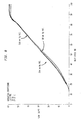
- Fig. 8 shows a representative flow vs. duty cycle characteristics for a purge valve at different manifold vacuum levels. It can be seen that the curves are substantially identical despite changing manifold vacuum.
Landscapes
- Engineering & Computer Science (AREA)
- Chemical & Material Sciences (AREA)
- Combustion & Propulsion (AREA)
- Mechanical Engineering (AREA)
- General Engineering & Computer Science (AREA)
- Magnetically Actuated Valves (AREA)
Description
Claims (14)
- An emission control valve (14) comprising:-characterised in that the control valve (14) further comprises a screw thread (60) formed on the tube (26); a socket (66) formed in the valve body (34, 36, 38) which has a complementary screw thread (68) for engaging the screw thread (60) on the tube (26) to provide axial location for the valve seat (62) within the interior space (42); and constraining means for constraining the tube (26) against further twisting on the body (34, 36, 38) and for sealing the tube (26) to the socket (66).a body (34, 36, 38) having an interior space (42) forming a part of a purge flow path through which a purge flow may pass;a tube (26) forming a section (48, 50, 52, 54) of the purge flow path and comprising an annular valve seat (62) which is disposed within the interior space (42) in circumscribing relation to the section of the purge flow path; anda valve element (33) controlled by a purge control signal in relation to the valve seat (62) for establishing the extent to which purge flow may pass from the interior space (42) to the tube (26);
- An emission control valve according to claim 1, wherein the constraining means comprises an adhering sealant that is applied between the tube (26) and the socket (66) to form a plug (164) that constrains the tube (26) against further twisting on the body (34, 36, 38) and seals the tube (26) to the socket (66).
- An emission control valve according to claim 1 or 2, wherein the tube (26) comprises a tubular wall (46) forming the section (48, 50, 52, 54) of the purge flow path, a ring (56) circumscribing and spaced radially outward of the tubular wall (46), and a radial wall (58) joining the ring (56) to the tubular wall (46), the screw thread (60) of the tube (26) being disposed on the ring (56).
- An emission control valve according to claim 3, wherein the valve seat (62) is at an axial end of the tubular wall (46), the section (48, 50, 52, 54) of the purge flow path in the tubular wall (46) comprising a sonic nozzle (28), the ring (56) being disposed axially in circumscribing relation to the sonic nozzle (28).
- An emission control valve according to any one of the preceding claims including force-balancing means which comprises a communication path (142, 168) from the section (48, 50, 52, 54) of the purge flow path in the tube (26) to an enclosed force-balancing space (168) that, when the valve element (33) is seated on the valve seat (62), communicates the section (48, 50, 52, 54) of the purge flow path in the tube (26) to the force-balancing space (168) to force-balance the valve element (33) so that it is substantially de-sensitized to changes in vacuum in the section (48, 50, 52, 54) of the purge flow path in the tube (26).
- An emission control valve according to claim 5, including a solenoid (30, 32) comprising an armature (32) for operating the valve element (33) and a bobbin (70, 72, 74, 76, 78, 80) that contains an electromagnetic coil (81) and has a hole for guiding the armature (32), the force-balancing space (168) being closed to the interior space (42) by a diaphragm (124) having an inner margin sealed to the armature (32) and an outer margin sealed to a portion of the solenoid (30, 32) that circumferentially bounds the bobbin hole (78).
- An emission control valve according to claim 6, wherein the solenoid (30, 32) comprises stator structure (86, 88, 90) providing, in cooperation with the armature (32), a magnetic circuit path, the stator structure (86, 88, 90) comprising an annular shunt (90) disposed within the interior space (42) and capturing the outer margin of the diaphragm (124) against the portion of the solenoid (30, 32) that circumferentially bounds the bobbin hole (78).
- An emission control valve according to claim 7, wherein the stator structure (86, 88, 90) comprises side wall structure (94) that extends axially of the solenoid (30, 32) and comprises retaining means (100, 102) for retaining the shunt (90) on the solenoid (30, 32).
- An emission control valve according to claim 8, wherein the retaining means (100, 102) comprises tabs (102) on the stator side wall structure (94) that have interference with margins (104) of notches (108) in the shunt (90).
- An emission control valve (14) according to any one of claims 1 to 5, the body (34, 36, 38) having an inlet port, an outlet port , and the interior space (42) being between the inlet port and the outlet port through which gaseous emissions pass, the control valve (14) further having a solenoid (30, 32) comprising an armature (32) for operating the valve element (33) and a bobbin (70, 72, 74, 76, 78, 80) which contains an electromagnetic coil (81) and has a hole for guiding the armature (32), stator structure (86, 88, 90) providing, in cooperation with the armature (32), a magnetic circuit path, wherein the stator structure (86, 88, 90) comprises side wall structure (94) that extends axially of the solenoid (32) and an annular shunt (90) at an end of the solenoid (32) providing an air gap in the magnetic circuit between the stator structure (86, 88, 90) and the armature (32), and retaining means (100, 102) for retaining the shunt (90) on the solenoid (30, 32) comprising tabs (102) on one of the stator side wall structure (94) and the shunt (90) and notches (108) in the other of the stator side wall structure (94) and the shunt (90), wherein the tabs (102) pass through the notches (108) and are in interference with margins (104) thereof.
- An emission control valve according to claim 10, wherein the notches (108) are in the shunt (90) and the tabs (102) are on the stator side wall structure (94).
- An emission control valve according to claim 11, wherein the stator side wall structure (94) comprises two diametrically opposite side walls, each containing plural tabs (102).
- An emission control valve according to any one of claims 10 to 12, wherein the shunt (90) comprises a curved inner margin (106) at the air gap.
- An evaporation emission control system (10) for an internal combustion engine fuel system which includes a fuel tank (16) and an engine (20) having an intake manifold (18), the evaporation emission control system comprising:-a fuel vapor collection canister (12) for collecting vapor generated by volatile fuel in the fuel tank (16); andan emission control valve (14) according to any preceding claim disposed in a purge flow path between the intake manifold (18) and the fuel vapor collection canister (12), the control valve (14) being controlled by the purge control signal to define the extent to which the control valve (14) allows purge flow through the purge flow path.
Priority Applications (1)
| Application Number | Priority Date | Filing Date | Title |
|---|---|---|---|
| EP00203572A EP1069304B1 (en) | 1996-06-13 | 1997-05-23 | Force-balanced sonic flow emission control valve |
Applications Claiming Priority (3)
| Application Number | Priority Date | Filing Date | Title |
|---|---|---|---|
| US08/662,554 US5630403A (en) | 1996-06-13 | 1996-06-13 | Force-balanced sonic flow emission control valve |
| US662554 | 1996-06-13 | ||
| PCT/CA1997/000352 WO1997047873A1 (en) | 1996-06-13 | 1997-05-23 | Force-balanced sonic flow emission control valve |
Related Child Applications (1)
| Application Number | Title | Priority Date | Filing Date |
|---|---|---|---|
| EP00203572A Division EP1069304B1 (en) | 1996-06-13 | 1997-05-23 | Force-balanced sonic flow emission control valve |
Publications (2)
| Publication Number | Publication Date |
|---|---|
| EP0904487A1 EP0904487A1 (en) | 1999-03-31 |
| EP0904487B1 true EP0904487B1 (en) | 2002-04-03 |
Family
ID=24658189
Family Applications (2)
| Application Number | Title | Priority Date | Filing Date |
|---|---|---|---|
| EP97922771A Expired - Lifetime EP0904487B1 (en) | 1996-06-13 | 1997-05-23 | Force-balanced sonic flow emission control valve |
| EP00203572A Expired - Lifetime EP1069304B1 (en) | 1996-06-13 | 1997-05-23 | Force-balanced sonic flow emission control valve |
Family Applications After (1)
| Application Number | Title | Priority Date | Filing Date |
|---|---|---|---|
| EP00203572A Expired - Lifetime EP1069304B1 (en) | 1996-06-13 | 1997-05-23 | Force-balanced sonic flow emission control valve |
Country Status (6)
| Country | Link |
|---|---|
| US (1) | US5630403A (en) |
| EP (2) | EP0904487B1 (en) |
| KR (1) | KR20000016601A (en) |
| BR (1) | BR9709789A (en) |
| DE (2) | DE69715477T2 (en) |
| WO (1) | WO1997047873A1 (en) |
Families Citing this family (32)
| Publication number | Priority date | Publication date | Assignee | Title |
|---|---|---|---|---|
| US5857446A (en) * | 1996-07-01 | 1999-01-12 | Norton; Peter | Fuel vapor source |
| US6050245A (en) * | 1997-02-12 | 2000-04-18 | Siemens Canada Limited | Canister vent valve having at least one sensor and single electric actuator operatively connected to a single electrical connector |
| DE19721562A1 (en) * | 1997-05-23 | 1998-11-26 | Bosch Gmbh Robert | Valve for the metered introduction of volatilized fuel |
| US5878725A (en) * | 1997-10-07 | 1999-03-09 | Borg-Warner Automotive, Inc. | Canister vent/purge valve |
| US5893354A (en) * | 1998-09-16 | 1999-04-13 | Eaton Corporation | Method of controlling fuel vapor canister purge flow and vapor management valve therefor |
| DE19901090A1 (en) * | 1999-01-14 | 2000-07-20 | Bosch Gmbh Robert | Valve for the metered introduction of volatilized fuel |
| DE60008869T2 (en) * | 1999-06-08 | 2004-08-05 | Johnson Controls Automotive Electronics | ELECTROMAGNETIC VALVE FOR VENTILATING DEVICE OF STEAMS |
| US6708905B2 (en) | 1999-12-03 | 2004-03-23 | Emissions Control Technology, Llc | Supersonic injector for gaseous fuel engine |
| US6457484B1 (en) * | 2000-01-25 | 2002-10-01 | Saturn Electronics & Engineering, Inc. | Solenoid fluid control valve with twist-on connection |
| US6631881B2 (en) * | 2000-08-08 | 2003-10-14 | Siemens Automotive Inc. | Single-stage fuel tank pressure control valve |
| US20040103877A1 (en) * | 2000-12-01 | 2004-06-03 | Mccoy James J. | Supersonic injector for gaseous fuel engine |
| JP4849715B2 (en) * | 2000-12-25 | 2012-01-11 | 株式会社不二工機 | Electromagnetic actuator |
| US6684901B1 (en) * | 2001-08-23 | 2004-02-03 | Deltrol Controls | Modular liquid dispensing valve |
| US6669165B2 (en) * | 2001-09-06 | 2003-12-30 | Delphi Technologies, Inc. | Solenoid valve assembly |
| US6666192B2 (en) | 2001-11-14 | 2003-12-23 | Delphi Technologies, Inc. | Fluid control valve and system |
| DE10161995A1 (en) * | 2001-12-18 | 2003-07-03 | Bosch Gmbh Robert | magnetic valve |
| US6968710B1 (en) * | 2002-03-26 | 2005-11-29 | Kozinski Richard C | Refrigeration compressor capacity limiting device |
| US6910674B2 (en) * | 2002-10-09 | 2005-06-28 | Maquet Critical Care Ab | Valve for use in a breathing apparatus |
| US7086383B2 (en) * | 2003-04-04 | 2006-08-08 | Siemens Vdo Automotive Inc. | Permanent magnet digital purge valve |
| WO2005012716A1 (en) * | 2003-07-25 | 2005-02-10 | Siemens Vdo Automotive Inc. | Integrated vapor control valve and sensor |
| US7451942B2 (en) * | 2003-10-20 | 2008-11-18 | Digicon, Inc. | Direct fuel injector assembly for a compressible natural gas engine |
| US7862004B2 (en) * | 2005-08-05 | 2011-01-04 | Bunn-O-Matic Corporation | Gas eliminating control valve |
| US20080000456A1 (en) * | 2006-06-30 | 2008-01-03 | Siemens Canada Limited | Cost-optimized canister purge valve |
| JP2008075827A (en) * | 2006-09-25 | 2008-04-03 | Denso Corp | Fluid control valve |
| JP4375436B2 (en) * | 2007-05-24 | 2009-12-02 | 株式会社デンソー | Valve device |
| US8156924B2 (en) * | 2007-10-17 | 2012-04-17 | Kohler Co. | Systems and methods for regulating purge flow rate in an internal combustion engine |
| US8677978B2 (en) * | 2010-03-03 | 2014-03-25 | Kohler Co. | System and method for carburetor venting |
| KR200474893Y1 (en) * | 2013-07-15 | 2014-10-23 | 황규관 | Small valve apparatus for prevention from sagging of excavator Tongs |
| US9683523B2 (en) * | 2013-10-14 | 2017-06-20 | Continental Automotive Systems, Inc. | On-board diagnostic check for evap latching valves |
| JP6176215B2 (en) * | 2014-09-25 | 2017-08-09 | 株式会社デンソー | Two-stage switching valve |
| CN105840352B (en) * | 2016-05-26 | 2018-11-09 | 宁波拓普智能刹车系统有限公司 | A kind of gasoline vapor purifier being driven using magnetic induction |
| US20240302000A1 (en) * | 2023-03-07 | 2024-09-12 | Boyd Hydrogen LLC | Compressed hydrogen vehicle fueling system having sonic choke flow control |
Family Cites Families (27)
| Publication number | Priority date | Publication date | Assignee | Title |
|---|---|---|---|---|
| US4085721A (en) * | 1966-05-09 | 1978-04-25 | Exxon Research & Engineering Co. | Evaporation purge control device |
| US4326489A (en) * | 1979-12-27 | 1982-04-27 | Ford Motor Company | Proportional flow fuel vapor purge control device |
| US4703737A (en) * | 1986-07-31 | 1987-11-03 | Bendix Electronics Limited | Vapor control valve and system therefor |
| US4773445A (en) * | 1986-10-10 | 1988-09-27 | Kaiser Aerospace And Electronics Corporation | Solenoid valve |
| US4932444A (en) * | 1987-10-19 | 1990-06-12 | Colt Industries Inc. | Fill neck assembly for vehicle mounted fuel vapor recovery system |
| DE3802664C1 (en) * | 1988-01-29 | 1988-10-13 | Fa. Carl Freudenberg, 6940 Weinheim, De | |
| DE3830722A1 (en) * | 1988-09-09 | 1990-03-15 | Freudenberg Carl Fa | DEVICE FOR FEEDING FUEL FUEL COMPONENTS INTO THE SUCTION PIPE OF AN INTERNAL COMBUSTION ENGINE |
| DE3844453C2 (en) * | 1988-12-31 | 1996-11-28 | Bosch Gmbh Robert | Valve for the metered admixture of volatilized fuel to the fuel-air mixture of an internal combustion engine |
| US4894072A (en) * | 1989-03-27 | 1990-01-16 | General Motors Corporation | High efficiency vapor storage canister |
| US5054454A (en) * | 1989-11-09 | 1991-10-08 | Ford Motor Company | Fuel vapor recovery control system |
| US5080078A (en) * | 1989-12-07 | 1992-01-14 | Ford Motor Company | Fuel vapor recovery control system |
| DE4100659C1 (en) * | 1991-01-11 | 1992-05-14 | Fa. Carl Freudenberg, 6940 Weinheim, De | |
| US5083546A (en) * | 1991-02-19 | 1992-01-28 | Lectron Products, Inc. | Two-stage high flow purge valve |
| JPH0741881Y2 (en) * | 1991-04-27 | 1995-09-27 | 東洋電装株式会社 | Evaporative fuel control valve device |
| US5184644A (en) * | 1991-05-30 | 1993-02-09 | Coltec Industries Inc. | Solenoid operated pressure regulating valve |
| JPH086647B2 (en) * | 1991-06-21 | 1996-01-29 | 京三電機株式会社 | Fuel evaporative emission control system |
| JPH0586923A (en) * | 1991-07-26 | 1993-04-06 | Nippon Soken Inc | Internal combustion engine having evaporated fuel purging device |
| US5373822A (en) * | 1991-09-16 | 1994-12-20 | Ford Motor Company | Hydrocarbon vapor control system for an internal combustion engine |
| US5249561A (en) * | 1991-09-16 | 1993-10-05 | Ford Motor Company | Hydrocarbon vapor sensor system for an internal combustion engine |
| US5117797A (en) * | 1991-10-17 | 1992-06-02 | Coltec Industries Inc. | Purge valve |
| US5363832A (en) * | 1992-05-14 | 1994-11-15 | Nippondenso Co., Ltd. | Fuel vapor purging control system with air/fuel ratio compensating system for internal combustion engine |
| US5277167A (en) * | 1993-02-04 | 1994-01-11 | Lectron Products, Inc. | Vapor management valve |
| US5413082A (en) * | 1994-01-19 | 1995-05-09 | Siemens Electric Limited | Canister purge system having improved purge valve |
| US5513832A (en) * | 1994-04-22 | 1996-05-07 | Lectron Products, Inc. | Variable force solenoid valve |
| US5429099A (en) * | 1994-09-08 | 1995-07-04 | Lectron Products, Inc. | Anti-permeation filter for vapor management valve |
| US5509395A (en) * | 1995-03-31 | 1996-04-23 | Siemens Electric Limited | Canister purge flow regulator |
| US5551406A (en) * | 1995-05-19 | 1996-09-03 | Siemens Electric Limited | Canister purge system having improved purge valve |
-
1996
- 1996-06-13 US US08/662,554 patent/US5630403A/en not_active Expired - Fee Related
-
1997
- 1997-05-23 DE DE69715477T patent/DE69715477T2/en not_active Expired - Fee Related
- 1997-05-23 DE DE69711622T patent/DE69711622T2/en not_active Expired - Fee Related
- 1997-05-23 WO PCT/CA1997/000352 patent/WO1997047873A1/en not_active Ceased
- 1997-05-23 KR KR1019980710197A patent/KR20000016601A/en not_active Abandoned
- 1997-05-23 EP EP97922771A patent/EP0904487B1/en not_active Expired - Lifetime
- 1997-05-23 BR BR9709789A patent/BR9709789A/en not_active IP Right Cessation
- 1997-05-23 EP EP00203572A patent/EP1069304B1/en not_active Expired - Lifetime
Also Published As
| Publication number | Publication date |
|---|---|
| EP1069304B1 (en) | 2002-09-11 |
| DE69711622D1 (en) | 2002-05-08 |
| US5630403A (en) | 1997-05-20 |
| WO1997047873A1 (en) | 1997-12-18 |
| BR9709789A (en) | 1999-08-10 |
| KR20000016601A (en) | 2000-03-25 |
| EP1069304A3 (en) | 2001-02-28 |
| EP0904487A1 (en) | 1999-03-31 |
| DE69715477D1 (en) | 2002-10-17 |
| DE69715477T2 (en) | 2003-06-05 |
| DE69711622T2 (en) | 2002-08-14 |
| EP1069304A2 (en) | 2001-01-17 |
Similar Documents
| Publication | Publication Date | Title |
|---|---|---|
| EP0904487B1 (en) | Force-balanced sonic flow emission control valve | |
| EP1007837B1 (en) | Automotive emission control valve with a counter-force mechanism | |
| EP0740741B2 (en) | Canister purge system having improved purge valve | |
| US5967487A (en) | Automotive emission control valve with a cushion media | |
| EP0776417B1 (en) | Coil for small diameter welded fuel injector | |
| KR100363489B1 (en) | Fuel injector having improved parallelism of impacting armature surface to impacted stop surface | |
| KR100375041B1 (en) | Shell component to protect injector from corrosion | |
| US5237980A (en) | On-board fuel vapor recovery system having improved canister purging | |
| KR100364612B1 (en) | Integrated engine intake manifold having a fuel vapor purge valve and an exhaust gas recirculation valve | |
| US6058913A (en) | Emission control valve with integral filter | |
| EP0923670B1 (en) | Integrated manifold and purge valve | |
| WO1996036805A1 (en) | Canister purge system having improved purge valve | |
| US7044111B2 (en) | Purge valve having permanent magnet armature | |
| US6073617A (en) | Manifold-mounted emission control valve | |
| US6223733B1 (en) | Exhaust gas recirculation valve | |
| JP3452900B2 (en) | Tuned linear purge solenoid valve | |
| JPH11303685A (en) | Electromagnetic gas fuel injection valve | |
| US5967172A (en) | Electric vacuum regulator valve | |
| EP0781915A1 (en) | Fuel injector |
Legal Events
| Date | Code | Title | Description |
|---|---|---|---|
| PUAI | Public reference made under article 153(3) epc to a published international application that has entered the european phase |
Free format text: ORIGINAL CODE: 0009012 |
|
| 17P | Request for examination filed |
Effective date: 19981204 |
|
| AK | Designated contracting states |
Kind code of ref document: A1 Designated state(s): DE FR GB IT |
|
| 17Q | First examination report despatched |
Effective date: 20000508 |
|
| GRAG | Despatch of communication of intention to grant |
Free format text: ORIGINAL CODE: EPIDOS AGRA |
|
| GRAG | Despatch of communication of intention to grant |
Free format text: ORIGINAL CODE: EPIDOS AGRA |
|
| GRAH | Despatch of communication of intention to grant a patent |
Free format text: ORIGINAL CODE: EPIDOS IGRA |
|
| GRAH | Despatch of communication of intention to grant a patent |
Free format text: ORIGINAL CODE: EPIDOS IGRA |
|
| REG | Reference to a national code |
Ref country code: GB Ref legal event code: IF02 |
|
| GRAA | (expected) grant |
Free format text: ORIGINAL CODE: 0009210 |
|
| AK | Designated contracting states |
Kind code of ref document: B1 Designated state(s): DE FR GB IT |
|
| REF | Corresponds to: |
Ref document number: 69711622 Country of ref document: DE Date of ref document: 20020508 |
|
| PLBE | No opposition filed within time limit |
Free format text: ORIGINAL CODE: 0009261 |
|
| STAA | Information on the status of an ep patent application or granted ep patent |
Free format text: STATUS: NO OPPOSITION FILED WITHIN TIME LIMIT |
|
| 26N | No opposition filed |
Effective date: 20030106 |
|
| PGFP | Annual fee paid to national office [announced via postgrant information from national office to epo] |
Ref country code: GB Payment date: 20040506 Year of fee payment: 8 |
|
| PGFP | Annual fee paid to national office [announced via postgrant information from national office to epo] |
Ref country code: FR Payment date: 20040525 Year of fee payment: 8 |
|
| PG25 | Lapsed in a contracting state [announced via postgrant information from national office to epo] |
Ref country code: IT Free format text: LAPSE BECAUSE OF NON-PAYMENT OF DUE FEES;WARNING: LAPSES OF ITALIAN PATENTS WITH EFFECTIVE DATE BEFORE 2007 MAY HAVE OCCURRED AT ANY TIME BEFORE 2007. THE CORRECT EFFECTIVE DATE MAY BE DIFFERENT FROM THE ONE RECORDED. Effective date: 20050523 Ref country code: GB Free format text: LAPSE BECAUSE OF NON-PAYMENT OF DUE FEES Effective date: 20050523 |
|
| PGFP | Annual fee paid to national office [announced via postgrant information from national office to epo] |
Ref country code: DE Payment date: 20050721 Year of fee payment: 9 |
|
| GBPC | Gb: european patent ceased through non-payment of renewal fee |
Effective date: 20050523 |
|
| PG25 | Lapsed in a contracting state [announced via postgrant information from national office to epo] |
Ref country code: FR Free format text: LAPSE BECAUSE OF NON-PAYMENT OF DUE FEES Effective date: 20060131 |
|
| REG | Reference to a national code |
Ref country code: FR Ref legal event code: ST Effective date: 20060131 |
|
| PG25 | Lapsed in a contracting state [announced via postgrant information from national office to epo] |
Ref country code: DE Free format text: LAPSE BECAUSE OF NON-PAYMENT OF DUE FEES Effective date: 20061201 |