EP0904231B1 - Verfahren und system zum ankern und positionieren eines wasserfahrzeuges, und wasserfahrzeug mit einem solchen system - Google Patents
Verfahren und system zum ankern und positionieren eines wasserfahrzeuges, und wasserfahrzeug mit einem solchen system Download PDFInfo
- Publication number
- EP0904231B1 EP0904231B1 EP97927503A EP97927503A EP0904231B1 EP 0904231 B1 EP0904231 B1 EP 0904231B1 EP 97927503 A EP97927503 A EP 97927503A EP 97927503 A EP97927503 A EP 97927503A EP 0904231 B1 EP0904231 B1 EP 0904231B1
- Authority
- EP
- European Patent Office
- Prior art keywords
- vessel
- anchor
- winches
- anchors
- anchor lines
- Prior art date
- Legal status (The legal status is an assumption and is not a legal conclusion. Google has not performed a legal analysis and makes no representation as to the accuracy of the status listed.)
- Expired - Lifetime
Links
Images

Classifications
-
- B—PERFORMING OPERATIONS; TRANSPORTING
- B63—SHIPS OR OTHER WATERBORNE VESSELS; RELATED EQUIPMENT
- B63B—SHIPS OR OTHER WATERBORNE VESSELS; EQUIPMENT FOR SHIPPING
- B63B21/00—Tying-up; Shifting, towing, or pushing equipment; Anchoring
- B63B21/50—Anchoring arrangements or methods for special vessels, e.g. for floating drilling platforms or dredgers
Definitions
- the invention relates to a method for positioning of a floating vessel against the wind and/or wave/current direction prevailing at any time, especially a vessel for the production of hydrocarbons from a subsea source.
- the invention relates to a system for anchoring and positioning of such a vessel, and a vessel including such a system.
- Such ships In connection with the operation of production vessels for offshore production of hydrocarbons there are known different types of systems for anchoring and/or positioning of the topical ship or vessel.
- Such ships usually are provided with a so-called “moonpool", i.e. a vertical opening through the hull of the ship, in which there is arranged equipment for connection and securing of the topical risers extending between the ship and e.g. one or more wellheads on the sea bed, for transport of the topical well flow from the subsea source.
- mispool i.e. a vertical opening through the hull of the ship, in which there is arranged equipment for connection and securing of the topical risers extending between the ship and e.g. one or more wellheads on the sea bed, for transport of the topical well flow from the subsea source.
- SAL system Section Anchor Loading
- the topical ship is provided with a mooring means in its bow portion, and where one or more anchor lines extend between the mooring means and an anchor device at the sea bed.
- the anchor device such as a suction anchor or a pile anchor, is provided with a swivel means for the anchoring line, to allow turning of the ship without any adverse influence on the anchor line.
- a dynamic positioning system as a supplement to the anchoring system.
- production vessels and/or storage vessels are kept anchored and positioned by means of a combined mooring and loading buoy which is anchored to the sea bed and in operation is introduced and secured in the moonpool of the ship, the construction being carried out in such a manner that the ship may turn or rotate about the buoy under the influence of wind, waves and water currents.
- Said turning of the ship is admitted in that the buoy is mounted in a rotating body or so-called “turret” which is permanently installed in the moonpool of the ship, or in that the buoy is of the bipartite type comprising a submerged, bottom-anchored centre member and an outer buoy member which is rotatably mounted thereon and in operation is introduced and secured in a submerged receiving space at the bottom of the ship.
- the last-mentioned buoy structure is known under the designation STP buoy, where the abbreviation STP stands for "Submerged Turret Production”.
- the object of the invention is to provide a method and a system for anchoring and positioning of a floating vessel, especially a vessel for the production of hydrocarbons, wherein the method enables the use of a simple anchoring and positioning system where a relatively expensive buoy anchoring system, and possibly an expensive dynamic positioning system, is avoided.
- a vessel for the production of hydrocarbons from a subsea source connected to the vessel via a number of risers the vessel including a system for anchoring and positioning of the vessel, which vessel is characterized by the features of claim 9.
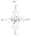
- a production vessel 1 for the production of hydrocarbons from a subsea source from which hydrocarbons are supplied to the ship via a number of risers which, at their upper ends, are secured in a suitable manner in relation to the ship.
- the risers 2 in this embodiment are shown to be fastened in a mounting unit 3 arranged at one side of the ship.
- the mounting unit 3 may be fastened to the ship side in a suitable manner, or it may be provided on or constituted by a separate floating unit, e.g. a suitable barge, which can be secured to or released from the ship as required.
- the risers are coupled, in a manner not further shown, to process equipment on the ship, for example via the midship manifold thereof (not shown).
- the vessel is anchored by means of a number of anchor lines 4 - 9 which, at one of their ends, are fastened to respective winches 10 - 12 and 13 - 15 placed at the bow portion 16 of the vessel and at the vessel stern 17, respectively, and at their other ends are fastened to respective anchors 18 - 21 anchored in the sea bed at places located at chosen horizontal distances from the vessel 1.
- the anchor lines comprise a forward pair of anchor lines 4, 5, a rearward pair of anchor lines 6, 7, an additional rearward anchor line 8, and an additional forward anchor line 9.
- the first pair of anchor lines 4, 5 has inner ends (i.e. the ends nearest to the vessel) which are connected to respective winches 10, 11 at the bow 16 of the vessel, and outer ends (i.e.
- the rearward pair of anchor lines 6, 7 has inner ends which are connected to respective winches 13, 14 at the stern of the vessel, and outer ends which are connected to a respective one of said two anchors 18, 19. As shown, the winches 13 and 14 are arranged on either side of the vessel.
- the rearward anchor line 8 is connected to a winch 15 at the stern 17 of the vessel, and to a third anchor 20 at a distance astern of the vessel, and the forward anchor line 9 is connected to a winch 12 at the bow 16 of the vessel, and to a fourth anchor 21 at a distance ahead of the vessel.
- the anchors 18 - 21 may be suction anchors or anchors of another suitable type.
- the winches 10 - 14 may be conventional motorized winches or windlasses of any suitable type.
- the anchors 18 - 21 are arranged with a chosen mutual angular distance measured along a horizontal circle having its centre in the vessel.
- the centre of the circle suitably may be situated in the yaw axis of the vessel, i.e. its vertical axis of rotation.
- the anchors are arranged at a mutual annular distance of ca. 90°.
- the two anchors 18, 19 at opposite sides of the vessel 1 are located symmetrically about the longitudinal axis L of the vessel when the anchor lines 4, 5 and 6, 7 in each of said pairs are equally long.
- both the rearward anchor line 8 and the forward anchor line 9 are essentially parallel to the longitudinal axis L of the vessel when the anchor lines 4, 5 and 6, 7 in each of said pairs are equally long.
- the vessel 1 by means of the described system may be turned and oriented with its longitudinal axis L within an angular range of near up to 180°, so that the vessel can be positioned in a desired orientation, more specifically so that the bow or the stern is oriented against the topical wind and/or wave/current direction.
- This turning is achieved by carrying out hauling-in or tightening of chosen anchor lines at the same time as there is carried out a suitable veering-out or slackening of other anchor lines, in both cases by means of the associated winches.
- DP system dynamic positioning system
- Fig. 1 the vessel 1 is shown in a first position (with solid lines) in which the bow of the vessel may be oriented against the prevailing wind or current direction, and a second position (shown stippled) in which the vessel is turned about 75° from the first position.
- This turning is achieved by a tightening of the anchor lines 5 and 6, and a simultaneous suitable slackening of the remaining anchor lines 4, 7, 8, 9.
- the obtainable turning here will be somewhat less than 90° in each direction, but in practice this will be sufficient on the topical places of use.
- the stern of the vessel is formed with a rounded or bow-like shape, for the achievement of good flow conditions there, when the wind/current comes in from the stern of the vessel.
- Fig. 2 there is shown a modified embodiment of the system according to the invention. Corresponding elements are designated by similar reference numerals in Figs. 1 and 2.
- the vessel 22 in Fig. 2 is provided with a through-going hull opening or moonpool 23 in which the topical number or the bundle of risers 24 is introduced and connected in a conventional manner not further shown.
- the shown riser arrangements also might have been interchanged in relation to the vessels.
- the anchoring and positioning system in Fig. 2 this largely corresponds to the system of Fig. 1, apart from the fact that the forward anchor line 9 in Fig. 1, and therewith also the associated winch 12 and the associated anchor 21, are omitted.
- the angular range within which the vessel 22 may be turned by hauling-in and slackening of the topical anchor lines becomes somewhat reduced in relation to the embodiment according to Fig. 1.
- the embodiment according to Fig. 2 may be of current interest in offshore regions where the wind and current directions are particularly stable, and where it is very unlikely that there will occur a strong wind coming from a direction lying outside of the possible angular range of vessel turning.
- the anchoring and positioning system according to the invention may be used also on relatively large ocean depths, for example up to about 1000 m and more.
- the horizontal distance between the vessel and the anchor will vary, according to the topical operational conditions and the depths at the place of use, and dependent on the type of anchor lines used. Topical horizontal distances are expected to lie in the range of 0,5-2 km.
Landscapes
- Chemical & Material Sciences (AREA)
- Engineering & Computer Science (AREA)
- Combustion & Propulsion (AREA)
- Mechanical Engineering (AREA)
- Ocean & Marine Engineering (AREA)
- Earth Drilling (AREA)
- Filling Or Discharging Of Gas Storage Vessels (AREA)
- Underground Structures, Protecting, Testing And Restoring Foundations (AREA)
Claims (9)
- Verfahren zum Verankern eines schwimmenden Wasserfahrzeugs und zur Positionierung des Wasserfahrzeugs gegen die zu beliebiger Zeit vorherrschende Wind- und/oder Wellen/Strömungsrichtung, wobei eine Anzahl von Ankerleinen verwendet werden, die an inneren Enden mit Winschen an Bug und Heck des Wasserfahrzeugs verbunden sind und an äußeren Enden mit jeweiligen Ankern verbunden sind, die im Meeresboden in einer Entfernung vom Wasserfahrzeug verankert sind, wobei das Wasserfahrzeug durch Dichtholen beziehungsweise Fieren ausgewählter Ankerleinen mittels der zugehörigen Winden in eine gewünschte Position gedreht wird, dadurch gekennzeichnet, daß ein vorderes Paar von Ankerleinen an deren inneren Enden mit jeweiligen Winschen am Bug des Wasserfahrzeugs verbunden ist und an deren äußeren Enden mit jeweils einem von zwei Ankern auf gegenüberliegenden Seiten des Wasserfahrzeugs verbunden ist, daß ein rückwärtiges Paar von Ankerleinen an deren inneren Enden mit jeweiligen Winschen am Heck des Wasserfahrzeugs verbunden ist und an deren äußeren Enden mit jeweils einem der zwei Anker verbunden ist, und daß eine zusätzliche Ankerleine mit einer zusätzlichen Winsch entweder am Bug oder am Heck des Wasserfahrzeugs und mit einem dritten Anker entweder vor dem Wasserfahrzeug oder achteraus von ihm verbunden ist, so daß das Wasserfahrzeug durch ein geeignetes Dichtholen beziehungsweise Fieren der Ankerleinen innerhalb eines Winkelbereichs von 160 - 180° gedreht werden kann.
- System zum Verankern und zum Positionieren eines schwimmenden Wasserfahrzeugs (1; 22), insbesondere eines Wasserfahrzeugs zur Produktion von Kohlenwasserstoffen aus einer Unterwasserquelle, das eine Anzahl von Ankerleinen (4 - 9) umfaßt, die an ihren inneren Enden mit Winschen (10 - 15) an Bug und Heck des Wasserfahrzeugs verbunden sind und an äußeren Enden mit jeweiligen Ankern (18-21) verbunden sind, die im Meeresboden in einer Entfernung vom Wasserfahrzeug (1; 22) verankert sind, so daß das Wasserfahrzeug durch Dichtholen beziehungsweise Fieren ausgewählter Ankerleinen mittels der zugehörigen Winschen gedreht werden kann, dadurch gekennzeichnet, daß es folgendes umfaßt: ein vorderes Paar von Ankerleinen (4, 5), die an ihren inneren Enden mit jeweiligen Winschen (10, 11) am Bug (16) des Wasserfahrzeugs (1; 22) verbunden sind und an ihren äußeren Enden mit jeweils einem von zwei Ankern (18, 19) auf gegenüberliegenden Seiten des Wasserfahrzeugs (1; 22) verbunden sind, ein rückwärtiges Paar von Ankerleinen (6, 7), die an ihren inneren Enden mit jeweiligen Winschen (13, 14) am Heck (17) des Wasserfahrzeugs (1; 22) verbunden sind und an ihren äußeren Enden mit jeweils einem der zwei Anker (18, 19) verbunden sind, und eine zusätzliche rückwärtige Ankerleine (8), die mit einer zusätzlichen Winsch (15) am Heck (17) des Wasserfahrzeugs und mit einem dritten Anker (20) achteraus vom Wasserfahrzeug verbunden ist.
- System nach Anspruch 2, dadurch gekennzeichnet, daß die jeweiligen Winschen (13, 14) am Heck (17) des Wasserfahrzeugs auf beiden Seiten des Wasserfahrzeugs (1; 22) positioniert sind.
- System nach Anspruch 2 oder 3, dadurch gekennzeichnet, daß es eine zusätzliche vordere Ankerleine (9) umfaßt, die mit einer Winsch (12) am Bug (16) des Wasserfahrzeugs und einem vierten Anker (21) vor dem Wasserfahrzeug verbunden ist.
- System nach einem der Ansprüche 2-4, dadurch gekennzeichnet, daß die zwei Anker (18, 19) auf gegenüberliegenden Seiten des Wasserfahrzeugs (1; 22) symmetrisch zur Längsachse (L) des Wasserfahrzeugs liegen, wenn die Ankerleinen (4, 5 beziehungsweise 6, 7) in jedem der Paare im wesentlichen gleich lang sind.
- System nach Anspruch 5, dadurch gekennzeichnet, daß die zusätzliche rückwärtige Ankerleine (8) im wesentlichen parallel zur Längsachse (L) des Wasserfahrzeugs (1; 22) ist, wenn die Ankerleinen (4, 5 beziehungsweise 6, 7) in jedem der Paare im wesentlichen gleich lang sind.
- System nach Anspruch 4 und 5, dadurch gekennzeichnet, daß die zusätzliche vordere Ankerleine (9) im wesentlichen parallel zur Längsachse (L) des Wasserfahrzeugs (1) ist, wenn die Ankerleinen (4, 5 beziehungsweise 6, 7) in jedem der Paare im wesentlichen gleich lang sind.
- System nach einem der Ansprüche 2-7, dadurch gekennzeichnet, daß die Anker (18-21) in einem gewählten gegenseitigen Winkelabstand positioniert sind, der längs eines horizontalen Kreises gemessen wird, der seine Mittel im Wasserfahrzeug (1; 22) hat.
- Wasserfahrzeug zur Produktion von Kohlenwasserstoffen aus einer über eine Anzahl von Steigleitungen (2; 23) mit dem Wasserfahrzeug (1; 22) verbundenen Unterwasserquelle, wobei das Wasserfahrzeug (1; 22) ein System zum Verankern und zum Positionieren des Wasserfahrzeugs umfaßt, wobei das System eine Anzahl von Ankerleinen (4 - 9) umfaßt, die an ihren inneren Enden mit Winschen (10 - 15) an Bug und Heck des Wasserfahrzeugs und an äußeren Enden mit jeweiligen Ankern (18 - 21) verbunden sind, die im Meeresboden in einer Entfernung vom Wasserfahrzeug (1; 22) verankert sind, so daß das Wasserfahrzeug durch Dichtholen beziehungsweise Fieren ausgewählter Ankerleinen mittels der zugehörigen Winschen gedreht werden kann, dadurch gekennzeichnet, daß das System folgendes umfaßt: ein vorderes Paar von Ankerleinen (4, 5), die an ihren inneren Enden mit jeweiligen Winschen (10, 11) am Bug (16) des Wasserfahrzeugs (1; 22) verbunden sind und an ihren äußeren Enden mit jeweils einem von zwei Ankern (18, 19) auf gegenüberliegenden Seiten des Wasserfahrzeugs (1; 22) verbunden sind, ein rückwärtiges Paar von Ankerleinen (6, 7), die an ihren inneren Enden mit jeweiligen Winschen (13, 14) am Heck (17) des Wasserfahrzeugs (1; 22) verbunden sind und an ihren äußeren Enden mit jeweils einem der zwei Anker (18, 19) verbunden sind, und eine zusätzliche rückwärtige Ankerleine (8), die mit einer zusätzlichen Winsch (15) am Heck (17) des Wasserfahrzeugs und mit einem dritten Anker (20) achteraus vom Wasserfahrzeug verbunden ist.
Applications Claiming Priority (3)
| Application Number | Priority Date | Filing Date | Title |
|---|---|---|---|
| NO962454 | 1996-06-11 | ||
| NO19962454A NO315265B1 (no) | 1996-06-11 | 1996-06-11 | Fremgangsmåte og system for forankring og posisjonering av et flytende fartöy, og et fartöy som omfatter et slikt system |
| PCT/NO1997/000149 WO1997047516A1 (en) | 1996-06-11 | 1997-06-09 | Method and system for anchoring and positioning of a floating vessel, and a vessel including such a system |
Publications (2)
| Publication Number | Publication Date |
|---|---|
| EP0904231A1 EP0904231A1 (de) | 1999-03-31 |
| EP0904231B1 true EP0904231B1 (de) | 2002-03-20 |
Family
ID=19899510
Family Applications (1)
| Application Number | Title | Priority Date | Filing Date |
|---|---|---|---|
| EP97927503A Expired - Lifetime EP0904231B1 (de) | 1996-06-11 | 1997-06-09 | Verfahren und system zum ankern und positionieren eines wasserfahrzeuges, und wasserfahrzeug mit einem solchen system |
Country Status (7)
| Country | Link |
|---|---|
| EP (1) | EP0904231B1 (de) |
| AU (1) | AU3195297A (de) |
| BR (1) | BR9710847A (de) |
| ID (1) | ID19491A (de) |
| NO (1) | NO315265B1 (de) |
| OA (1) | OA10932A (de) |
| WO (1) | WO1997047516A1 (de) |
Families Citing this family (6)
| Publication number | Priority date | Publication date | Assignee | Title |
|---|---|---|---|---|
| AU776984B2 (en) | 1999-08-09 | 2004-09-30 | Single Buoy Moorings Inc. | Active semi-weathervaning anchoring system |
| US6692192B2 (en) * | 2002-05-03 | 2004-02-17 | Single Buoy Moorings Inc. | Spread moored midship hydrocarbon loading and offloading system |
| US9976535B2 (en) | 2005-11-07 | 2018-05-22 | Gwave Llc | System for producing energy through the action of waves |
| NO336244B1 (no) * | 2006-10-17 | 2015-06-29 | Sevan Marine Asa | Fremgangsmåte for å fortøye et konvensjonelt tankskip |
| CN102393624A (zh) * | 2011-04-29 | 2012-03-28 | 上海交通大学 | 基于环网冗余结构的挖泥船动力定位控制系统 |
| JP6454271B2 (ja) | 2012-06-04 | 2019-01-16 | ジーウェイブ エルエルシー | 波の作用によりエネルギーを生成するシステム |
Family Cites Families (4)
| Publication number | Priority date | Publication date | Assignee | Title |
|---|---|---|---|---|
| US3552343A (en) * | 1969-01-10 | 1971-01-05 | Pan American Petroleum Corp | Drilling ship mooring system |
| US3583354A (en) * | 1969-04-23 | 1971-06-08 | Don H Flickinger | Anchoring system for fating drilling vessel |
| US3822663A (en) * | 1972-10-10 | 1974-07-09 | H Boschen | Method and apparatus for mooring floating vessels |
| US4070981A (en) * | 1976-10-04 | 1978-01-31 | Guinn David C | Mooring system for floating drilling vessels |
-
1996
- 1996-06-11 NO NO19962454A patent/NO315265B1/no not_active IP Right Cessation
-
1997
- 1997-06-09 EP EP97927503A patent/EP0904231B1/de not_active Expired - Lifetime
- 1997-06-09 WO PCT/NO1997/000149 patent/WO1997047516A1/en not_active Ceased
- 1997-06-09 BR BR9710847-2A patent/BR9710847A/pt not_active IP Right Cessation
- 1997-06-09 AU AU31952/97A patent/AU3195297A/en not_active Abandoned
- 1997-06-10 ID IDP971975A patent/ID19491A/id unknown
-
1998
- 1998-12-04 OA OA9800232A patent/OA10932A/en unknown
Also Published As
| Publication number | Publication date |
|---|---|
| NO962454D0 (no) | 1996-06-11 |
| WO1997047516A1 (en) | 1997-12-18 |
| OA10932A (en) | 2002-02-18 |
| EP0904231A1 (de) | 1999-03-31 |
| AU3195297A (en) | 1998-01-07 |
| NO962454L (no) | 1997-12-12 |
| BR9710847A (pt) | 2000-01-11 |
| ID19491A (id) | 1998-07-16 |
| NO315265B1 (no) | 2003-08-11 |
Similar Documents
| Publication | Publication Date | Title |
|---|---|---|
| CA2681204C (en) | Floating platform for operation in regions exposed to extreme weather conditions | |
| CA2182293C (en) | A vessel for production and/or loading/unloading and transport of hydrocarbons from offshore fields, and/or for carrying out well operations | |
| NO125842B (de) | ||
| US6485343B1 (en) | Dynamic positioning dock-loading buoy (DPDL-buoy) and method for use of such a DPDL-buoy | |
| US5893333A (en) | Loading/unloading terminal, especially for loading or unloading of petroleum products | |
| US5820429A (en) | Arrangement in a loading/unloading buoy for use in shallow waters | |
| Rutkowski | A comparison between conventional buoy mooring CBM, single point mooring SPM and single anchor loading sal systems considering the hydro-meteorological condition limits for safe ship’s operation offshore | |
| EP0904231B1 (de) | Verfahren und system zum ankern und positionieren eines wasserfahrzeuges, und wasserfahrzeug mit einem solchen system | |
| AU1190900A (en) | Device for positioning of vessels | |
| US8381669B2 (en) | System for loading of hydrocarbons from a floating vessel | |
| US20030161690A1 (en) | Offshore loading or production system for dynamically positioned ships | |
| US6655312B1 (en) | Active semi-weathervaning anchoring system | |
| US4254523A (en) | Mooring installation | |
| US20100212570A1 (en) | Vessel mooring systems and methods | |
| WO1998030438A1 (en) | Arrangement of drilling and production ship | |
| WO2000021825A1 (en) | A loading buoy | |
| GB2336143A (en) | Mooring system | |
| CA2203022C (en) | A loading/unloading terminal, especially for loading or unloading of petroleum products | |
| US4654015A (en) | Mooring installation | |
| CA2680755C (en) | Method and device for connecting a tanker at sea | |
| WO1999044883A1 (en) | Surface vessel | |
| JPS6050096A (ja) | 海洋における石油生産貯蔵用タンク船の長期係留及び原油受入装置 |
Legal Events
| Date | Code | Title | Description |
|---|---|---|---|
| PUAI | Public reference made under article 153(3) epc to a published international application that has entered the european phase |
Free format text: ORIGINAL CODE: 0009012 |
|
| 17P | Request for examination filed |
Effective date: 19981128 |
|
| AK | Designated contracting states |
Kind code of ref document: A1 Designated state(s): FR |
|
| GRAG | Despatch of communication of intention to grant |
Free format text: ORIGINAL CODE: EPIDOS AGRA |
|
| 17Q | First examination report despatched |
Effective date: 20010419 |
|
| GRAG | Despatch of communication of intention to grant |
Free format text: ORIGINAL CODE: EPIDOS AGRA |
|
| GRAH | Despatch of communication of intention to grant a patent |
Free format text: ORIGINAL CODE: EPIDOS IGRA |
|
| GRAH | Despatch of communication of intention to grant a patent |
Free format text: ORIGINAL CODE: EPIDOS IGRA |
|
| GRAA | (expected) grant |
Free format text: ORIGINAL CODE: 0009210 |
|
| AK | Designated contracting states |
Kind code of ref document: B1 Designated state(s): FR |
|
| ET | Fr: translation filed | ||
| ET | Fr: translation filed | ||
| PLBE | No opposition filed within time limit |
Free format text: ORIGINAL CODE: 0009261 |
|
| STAA | Information on the status of an ep patent application or granted ep patent |
Free format text: STATUS: NO OPPOSITION FILED WITHIN TIME LIMIT |
|
| 26N | No opposition filed |
Effective date: 20021223 |
|
| REG | Reference to a national code |
Ref country code: FR Ref legal event code: TP Owner name: STATOIL PETROLEUM AS, NO Effective date: 20130704 Ref country code: FR Ref legal event code: CJ Effective date: 20130704 Ref country code: FR Ref legal event code: CD Owner name: STATOIL PETROLEUM AS, NO Effective date: 20130704 |
|
| REG | Reference to a national code |
Ref country code: FR Ref legal event code: PLFP Year of fee payment: 20 |
|
| PGFP | Annual fee paid to national office [announced via postgrant information from national office to epo] |
Ref country code: FR Payment date: 20160630 Year of fee payment: 20 |