EP0903834B1 - Sealing device for explosion-proof motors - Google Patents
Sealing device for explosion-proof motors Download PDFInfo
- Publication number
- EP0903834B1 EP0903834B1 EP98203020A EP98203020A EP0903834B1 EP 0903834 B1 EP0903834 B1 EP 0903834B1 EP 98203020 A EP98203020 A EP 98203020A EP 98203020 A EP98203020 A EP 98203020A EP 0903834 B1 EP0903834 B1 EP 0903834B1
- Authority
- EP
- European Patent Office
- Prior art keywords
- sealing device
- casing
- elastic
- explosion
- driving shaft
- Prior art date
- Legal status (The legal status is an assumption and is not a legal conclusion. Google has not performed a legal analysis and makes no representation as to the accuracy of the status listed.)
- Expired - Lifetime
Links
- 238000007789 sealing Methods 0.000 title claims description 40
- 239000012528 membrane Substances 0.000 claims description 18
- 238000005096 rolling process Methods 0.000 claims description 8
- 239000000463 material Substances 0.000 claims description 5
- 239000000945 filler Substances 0.000 claims description 4
- 238000001816 cooling Methods 0.000 claims description 3
- 238000004880 explosion Methods 0.000 claims description 3
- 239000002184 metal Substances 0.000 claims 1
- 238000003825 pressing Methods 0.000 claims 1
- 238000012797 qualification Methods 0.000 description 2
- 230000008878 coupling Effects 0.000 description 1
- 238000010168 coupling process Methods 0.000 description 1
- 238000005859 coupling reaction Methods 0.000 description 1
- 230000001419 dependent effect Effects 0.000 description 1
- 230000007613 environmental effect Effects 0.000 description 1
- 239000002360 explosive Substances 0.000 description 1
- 239000003517 fume Substances 0.000 description 1
- 230000000670 limiting effect Effects 0.000 description 1
- 239000007788 liquid Substances 0.000 description 1
- 238000003754 machining Methods 0.000 description 1
- 230000014759 maintenance of location Effects 0.000 description 1
- 238000004519 manufacturing process Methods 0.000 description 1
- 238000012986 modification Methods 0.000 description 1
- 230000004048 modification Effects 0.000 description 1
- 238000000926 separation method Methods 0.000 description 1
- 239000007787 solid Substances 0.000 description 1
- 239000000126 substance Substances 0.000 description 1
Images

Classifications
-
- H—ELECTRICITY
- H02—GENERATION; CONVERSION OR DISTRIBUTION OF ELECTRIC POWER
- H02K—DYNAMO-ELECTRIC MACHINES
- H02K5/00—Casings; Enclosures; Supports
- H02K5/04—Casings or enclosures characterised by the shape, form or construction thereof
- H02K5/12—Casings or enclosures characterised by the shape, form or construction thereof specially adapted for operating in liquid or gas
- H02K5/136—Casings or enclosures characterised by the shape, form or construction thereof specially adapted for operating in liquid or gas explosion-proof
-
- H—ELECTRICITY
- H02—GENERATION; CONVERSION OR DISTRIBUTION OF ELECTRIC POWER
- H02K—DYNAMO-ELECTRIC MACHINES
- H02K5/00—Casings; Enclosures; Supports
- H02K5/04—Casings or enclosures characterised by the shape, form or construction thereof
- H02K5/12—Casings or enclosures characterised by the shape, form or construction thereof specially adapted for operating in liquid or gas
- H02K5/124—Sealing of shafts
Definitions
- Explosion-proof motors can be manufactured, depending on the load to be driven, with driving shaft supports equipped with rolling bearings or with a plain bearing (bushing).
- the considerable thickness of the passage makes the motor unsuitable for use as an explosion-proof motor.
- Figure 1 is a schematic view of a conventional driving shaft 1, whose outer surface is machined so as to form a labyrinth-like profile 2 which accommodates the sealing device 3 having a complementarily shaped labyrinth-like profile and being rigidly coupled to the casing 4 of the motor.
- EP-A-0 472 929 discloses a sealing device for a refiner.
- the aim of the present invention is to provide a sealing device for explosion-proof motors which allows to maintain the free space between the casing and the driving shaft at a constant value which is equal to the minimum prescribed value.
- an object of the present invention is to provide a sealing device for explosion-proof motors which allows to maintain the free space between the casing and the shaft at a minimum value for any driving shaft size.
- Another object of the present invention is to provide a sealing device for explosion-proof motors which is highly reliable, relatively easy to manufacture and at low costs.
- the elastic means are provided for example by an elastic membrane which has an omega-shaped cross-section or is accordion-shaped or has any other suitable shape and is welded between the first and second elements.
- the teeth 11 and 12 are meant to constitute supporting elements for the elastic membranes 9 to relieve the stress that may act thereon in case of an explosion inside the casing 4 of the motor. In this case, the stress the elastic membranes 9 are subjected to is damped by their contact against the teeth 11 and 12.
- the teeth 11 and 12 can advantageously have a curved profile that matches the profile of the membranes 9 in order to extend the contact surface of the elastic membranes 9 if they are subjected to stress.
- the second element 8 is advantageously provided with a flared portion 14 which deflects upward the flame (which might have developed because of an internal explosion), reducing the possibility of said flame being guided into the free space between the second element 8 and the driving shaft 1, and thus constituting an additional safety in addition to the two-part configuration of the sealing device and to the cooling fins provided on the surface of the second element 8.
- the materials employed may be any according to requirements and to the state of the art.
Landscapes
- Engineering & Computer Science (AREA)
- Power Engineering (AREA)
- Motor Or Generator Frames (AREA)
- Gas-Insulated Switchgears (AREA)
- Glass Compositions (AREA)
Description
- The present invention relates to a sealing device for explosion-proof motors. More particularly, the invention relates to a sealing device for preventing any flames generated within the casing of the motor from escaping outside through the gap between the driving shaft and the casing of said motor.
- It is known that explosion-proof motors, i.e., motors in which the safety aspect is essential because they must operate in dangerous environmental conditions, for example in the presence of flammable or explosive substances, have a sealing device which is arranged between the shaft of the motor and the casing and is rigidly coupled to said casing.
- Explosion-proof motors can be manufactured, depending on the load to be driven, with driving shaft supports equipped with rolling bearings or with a plain bearing (bushing).
- In the latter case, the coupling tolerances between the shaft and the support are greater than in the rolling-bearing solution. Given an equal precision class, machining tolerances are a function of size and increase as said size increases.
- Accordingly, larger driving shafts require tolerances which are higher in terms of absolute value and are more critical as regards providing the seal.
- Qualification tests for motors are performed while the motor is motionless and/or rotating.
- In view of what has been described above, the qualification of bushing-supported motors is more critical for the following reasons:
- -- the size of the passage through the sealing device is larger;
- Accordingly, the considerable thickness of the passage makes the motor unsuitable for use as an explosion-proof motor.
- Moreover, the driving shaft must be shaped appropriately so as to form a sort of labyrinth which loosely couples in the complementarily shaped sealing device.
- Figure 1 is a schematic view of a
conventional driving shaft 1, whose outer surface is machined so as to form a labyrinth-like profile 2 which accommodates the sealing device 3 having a complementarily shaped labyrinth-like profile and being rigidly coupled to thecasing 4 of the motor. - In order to allow the
driving shaft 1 to rotate freely, a certain clearance, designated by thereference numerals 5 and 6 in Figure 1, must necessarily be left. - Since the
driving shaft 1 must rotate within the sealing device 3, it is also necessary to leave, between theshaft 1 and the sealing device 3, a certain space which does not comply with standards concerning explosion-proof motors. - EP-A-0 472 929 discloses a sealing device for a refiner.
- The aim of the present invention is to provide a sealing device for explosion-proof motors which allows to maintain the free space between the casing and the driving shaft at a constant value which is equal to the minimum prescribed value.
- Within the scope of this aim, an object of the present invention is to provide a sealing device for explosion-proof motors which allows to maintain the free space between the casing and the shaft at a minimum value for any driving shaft size.
- Another object of the present invention is to provide a sealing device for explosion-proof motors which allows to improve the ability to extinguish the flame which might be generated inside the motor casing.
- Another object of the present invention is to provide a sealing device for explosion-proof motors which is highly reliable, relatively easy to manufacture and at low costs.
- This aim, these objects and others which will become apparent hereinafter are achieved by a sealing device with the features of
claim 1. Preferred embodiments are defined in the dependent claims. Further characteristics and advantages of the invention will become apparent from the following detailed description of a preferred but not exclusive embodiment of the device according to the invention, illustrated only by way of non-limitative example in the accompanying drawings, wherein: - Figure 1 is a partial sectional view of a driving shaft accommodated in a casing of an explosion-proof motor, with a conventional sealing device;
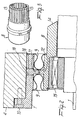
- Figure 2 is a partial sectional view, similar to Figure 1 but showing in this case the sealing device according to the present invention;
- Figure 3 is a perspective view of a portion of the sealing device according to the present invention; and
- Figure 4 is a perspective view of an elastic element which is part of the sealing device according to the present invention.
- In the various figures, identical elements are designated by the same reference numerals.
- With reference to Figures 2 to 4, the sealing device according to the present invention is constituted by a first sealing element 7, which is coupled to the
casing 4 of the motor, and by a second sealing element 8, which is coupled to theshaft 1 of the motor through the interposition ofrolling means 15, said rolling means being advantageously provided, for example, by a rolling bearing. - Elastic means 9 are provided to connect the first element 7 to the second element 8 so as to allow a relative movement between the first element 7 and the second element 8.
- Advantageously, the elastic means are provided for example by an elastic membrane which has an omega-shaped cross-section or is accordion-shaped or has any other suitable shape and is welded between the first and second elements.
- In detail, the elastic membrane has an annular configuration, as shown in Figure 4, and two
elastic membranes 9 are provided. - In this manner it is possible to reduce to a minimum the space between the second sealing element 8 and the
shaft 1, since the movement of the shaft with respect to the casing, during rotation, is allowed by theelastic means 9. - The first element 7 is advantageously connected to the
casing 4 through aconnecting means 10 which rigidly couples the element 7 thereto. - The first element and the second element are advantageously provided with a tooth each; said teeth are respectively designated by the
reference numerals 11 and 12, face each other and are arranged so that there is one of theelastic membranes 9 on either side of the twoteeth 11 and 12. - The
teeth 11 and 12 are meant to constitute supporting elements for theelastic membranes 9 to relieve the stress that may act thereon in case of an explosion inside thecasing 4 of the motor. In this case, the stress theelastic membranes 9 are subjected to is damped by their contact against theteeth 11 and 12. - For this purpose, the
teeth 11 and 12 can advantageously have a curved profile that matches the profile of themembranes 9 in order to extend the contact surface of theelastic membranes 9 if they are subjected to stress. - The spot-welds between the
membranes 9 and the first and second elements 7 and 8 can be rounded, eliminating the sharp edges so as to improve the resistance of the membranes stressed by the rotation of thedriving shaft 1 inside thecasing 4. - A filler material can also be provided between the
membranes 9 and the elements 7 and 8 which can be solid or liquid (for example oil). - In this case, filling and draining
channels 18 must be provided to introduce said filler material in the free space between the membranes and the sealing elements 7 and 8. - The second element 8 constitutes a two-part bushing, where the surface of the free portion (i.e., the portion whereto the
elastic membrane 9 is not welded or otherwise connected) has a series of longitudinal slits, designated by thereference numeral 13 in Figure 3, forming a plurality of fins which accordingly have a longitudinal configuration and a radial direction, to extinguish the flame that might develop inside the sealing channel. - Flame extinguishing is due to the cooling of said flame to a temperature below the propagation stability value: this is an extremely rapid phenomenon and the exchange surface is limited.
- The presence of the fins on the surface of the second element 8 offers the following advantages:
- -- an increase by one order of magnitude of the exchange surface;
- -- the expansion of the fumes inside the channels between mutually adjacent fins;
- -- an increase in the retention time and in heat exchange.
- The flame cannot propagate in the channels between adjacent fins since the size of said channels is advantageously chosen so that it is smaller than the minimum size deemed safe for the propagation of a flame inside an explosion-proof motor.
- Moreover, the second element 8 is advantageously provided with a flared
portion 14 which deflects upward the flame (which might have developed because of an internal explosion), reducing the possibility of said flame being guided into the free space between the second element 8 and thedriving shaft 1, and thus constituting an additional safety in addition to the two-part configuration of the sealing device and to the cooling fins provided on the surface of the second element 8. - In practice it has been observed that the sealing device according to the invention fully achieves the intended aim, since it allows to provide an optimum seal for an explosion-proof motor, minimizing the space between the casing and the shaft, through the separation of the sealing element into two mutually elastically connected parts.
- The device thus conceived is susceptible of numerous modifications and variations, all of which are within the scope of the inventive concept as defined in the claims.
- In practice, the materials employed, so long as they are compatible with the specific use, as well as the dimensions, may be any according to requirements and to the state of the art.
- Where technical features mentioned in any claim are followed by reference signs, those reference signs have been included for the sole purpose of increasing the intelligibility of the claims and accordingly, such reference signs do not have any limiting effect on the interpretation of each element identified by way of example by such reference signs.
Claims (10)
- A sealing device for explosion-proof motors having a motor casing and a driving shaft rotatable in the casing, comprising a first element which is coupled to the motor casing, a second element which is coupled to the driving shaft through rolling means, said first and second element being mutually coupled by way of elastic means so as to allow their relative movement, characterized in that it comprises, on a surface of said second element, a plurality of longitudinal slits, said slits forming a plurality of radially inclined fins for flame cooling and extinguishing.
- The sealing device of claim 1, characterized in that said elastic means are constituted by at least one elastic membrane which is rigidly connected to said first element and to said second element.
- The sealing device of claim 2, characterized in that at least one of said first and second elements has a tooth, said tooth constituting an abutment for said elastic membrane upon development of an internal explosion applying pressure to said elastic membrane.
- The sealing device of claim 2, characterized in that it comprises two elastic membranes, each of which is connected to said first and second elements.
- The sealing device of claim 1, characterized in that said rolling means comprise a roller bearing which is rigidly coupled to said second element.
- The sealing device of claim 1, characterized in that it comprises connecting means for connecting said first element to said casing.
- The sealing device of claim 1, characterized in that said second element has un upper surface which is directed toward the inside of said casing and is inclined in order to deflect the flame away from the free space between said second element and said driving shaft.
- The sealing device of claim 1, characterized in that it comprises a free space between said elastic means and said first and second elements, said free space filled with a filler material.
- The sealing device of claim 8, characterized in that it comprises two filling and draining channels provided in said first element for introduction and draining of said filler material.
- The sealing device of claim 1, characterized in that said at least one elastic membrane is made of metal.
Applications Claiming Priority (2)
| Application Number | Priority Date | Filing Date | Title |
|---|---|---|---|
| IT97MI002111A IT1295022B1 (en) | 1997-09-17 | 1997-09-17 | SEALING DEVICE FOR EXPLOSION-PROOF MOTORS |
| ITMI972111 | 1997-09-17 |
Publications (3)
| Publication Number | Publication Date |
|---|---|
| EP0903834A2 EP0903834A2 (en) | 1999-03-24 |
| EP0903834A3 EP0903834A3 (en) | 2001-03-14 |
| EP0903834B1 true EP0903834B1 (en) | 2007-02-14 |
Family
ID=11377886
Family Applications (1)
| Application Number | Title | Priority Date | Filing Date |
|---|---|---|---|
| EP98203020A Expired - Lifetime EP0903834B1 (en) | 1997-09-17 | 1998-09-09 | Sealing device for explosion-proof motors |
Country Status (4)
| Country | Link |
|---|---|
| US (1) | US6264204B1 (en) |
| EP (1) | EP0903834B1 (en) |
| DE (1) | DE69837065T2 (en) |
| IT (1) | IT1295022B1 (en) |
Families Citing this family (6)
| Publication number | Priority date | Publication date | Assignee | Title |
|---|---|---|---|---|
| US6747383B2 (en) | 2002-04-09 | 2004-06-08 | Honeywell International, Inc. | Generator with hydraulically mounted stator rotor |
| US20080248999A1 (en) * | 2007-04-04 | 2008-10-09 | Biodel Inc. | Amylin formulations |
| AU2006259933A1 (en) * | 2005-06-22 | 2006-12-28 | Itt Manufacturing Enterprises Inc. | Device for a rotating gland seal |
| FR2915032B1 (en) | 2007-04-12 | 2009-11-13 | Leroy Somer Moteurs | ANTI-FLAGING ROTATING MACHINE |
| DE102008007576A1 (en) * | 2008-02-05 | 2009-09-03 | Brose Fahrzeugteile GmbH & Co. Kommanditgesellschaft, Würzburg | Hollow shaft mounting motor for installation in a housing |
| EP3148055A1 (en) * | 2015-09-28 | 2017-03-29 | Siemens Aktiengesellschaft | Electric machine, labyrinth seal for an electric machine and method for sealing of an electric machine |
Family Cites Families (11)
| Publication number | Priority date | Publication date | Assignee | Title |
|---|---|---|---|---|
| DE2410692A1 (en) * | 1974-03-06 | 1975-09-11 | Knorr Bremse Gmbh | MOUNTING A SPEED ENCODER, ESPECIALLY ON A VEHICLE WHEEL AXLE |
| DE2706511A1 (en) * | 1977-02-16 | 1978-08-17 | Hermetic Pumpen Gmbh | Motor-pump unit with rotor tube - has pumped medium flowing through rotor space for cooling and shaft bearings are in lubricant chambers |
| GB1600515A (en) * | 1978-04-18 | 1981-10-14 | Glacier Metal Co Ltd | Annular seal |
| DE2901111A1 (en) * | 1979-01-12 | 1980-07-17 | Siemens Ag | Bearing shield for encapsulated electric machine - has one-piece bearing casing with inner axial projection forming circular seal on shaft |
| JPS59100128U (en) * | 1982-12-23 | 1984-07-06 | 株式会社ニフコ | oil damper |
| DE3713921A1 (en) * | 1987-04-25 | 1988-11-10 | Flender A F & Co | Shaft seal |
| CA1269693A (en) * | 1987-05-13 | 1990-05-29 | Robert Ross Hamilton | Explosion-proof electrical generator system |
| DE3804602A1 (en) * | 1988-02-13 | 1989-08-24 | Klein Schanzlin & Becker Ag | Explosionproof split-cage motor |
| IT1221373B (en) * | 1988-04-29 | 1990-06-27 | Varvel Spa | CONTINUOUS SPEED VARIATOR |
| DE3834214A1 (en) * | 1988-10-07 | 1990-04-12 | Burgmann Dichtungswerk Feodor | POETRY |
| EP0472929B1 (en) * | 1990-08-16 | 1995-03-01 | Voith Sulzer Stoffaufbereitung GmbH | Use of a sealing arrangement |
-
1997
- 1997-09-17 IT IT97MI002111A patent/IT1295022B1/en active IP Right Grant
-
1998
- 1998-09-09 EP EP98203020A patent/EP0903834B1/en not_active Expired - Lifetime
- 1998-09-09 DE DE69837065T patent/DE69837065T2/en not_active Expired - Lifetime
- 1998-09-11 US US09/151,586 patent/US6264204B1/en not_active Expired - Lifetime
Also Published As
| Publication number | Publication date |
|---|---|
| US6264204B1 (en) | 2001-07-24 |
| DE69837065D1 (en) | 2007-03-29 |
| DE69837065T2 (en) | 2007-08-30 |
| EP0903834A2 (en) | 1999-03-24 |
| ITMI972111A1 (en) | 1999-03-17 |
| IT1295022B1 (en) | 1999-04-27 |
| EP0903834A3 (en) | 2001-03-14 |
Similar Documents
| Publication | Publication Date | Title |
|---|---|---|
| US3756673A (en) | Stuffing box for a rotating shaft | |
| US3326453A (en) | Gas-bearing assembly | |
| US5395124A (en) | Retractible segmented packing ring for fluid turbines having gravity springs to neutralize packing segment weight forces | |
| US3622164A (en) | Seal for shafts | |
| EP0163450B1 (en) | Improvements in mechanical seals | |
| US5048978A (en) | Squeeze film damper seal | |
| US3132906A (en) | Hydrodynamic devices | |
| CA2167424A1 (en) | Emission seal | |
| CA2244048C (en) | Gas turbine interstage portion seal device | |
| US5518256A (en) | Floating-ring seal | |
| GB1421540A (en) | Shaft bearing assemblies | |
| US3901557A (en) | Bearing assemblies | |
| US5533739A (en) | Non-contacting seal with centering spring mounted in dovetailed grooved | |
| KR870007532A (en) | Reactor gas circulator and its use method | |
| US6264204B1 (en) | Sealing device for explosion-proof motors | |
| EP0921277A4 (en) | Seal structure between gas turbine discs | |
| JPS6375396A (en) | Multistage type in-line volute pump | |
| US3617068A (en) | Floating ring seal for rotating shafts | |
| EP0239519B1 (en) | Nutation damper | |
| KR100688134B1 (en) | Large Torsional Vibration Shock Absorber | |
| US5356273A (en) | Radial bearing assembly for a high inertia flywheel of a canned pump | |
| US3767279A (en) | Flexible flange for bearings, preferably rolling bearings | |
| US4564500A (en) | Oil pot for reactor coolant pump motor and apparatus for controlling the oil level therein | |
| US4219310A (en) | Construction of adjustable blade shaft bearing in axial-flow fan with adjustable blades | |
| EP3234417B1 (en) | Bearing isolator seal with enhanced rotor drive coupling |
Legal Events
| Date | Code | Title | Description |
|---|---|---|---|
| PUAI | Public reference made under article 153(3) epc to a published international application that has entered the european phase |
Free format text: ORIGINAL CODE: 0009012 |
|
| AK | Designated contracting states |
Kind code of ref document: A2 Designated state(s): DE FR GB IT |
|
| AX | Request for extension of the european patent |
Free format text: AL;LT;LV;MK;RO;SI |
|
| PUAL | Search report despatched |
Free format text: ORIGINAL CODE: 0009013 |
|
| AK | Designated contracting states |
Kind code of ref document: A3 Designated state(s): AT BE CH CY DE DK ES FI FR GB GR IE IT LI LU MC NL PT SE |
|
| AX | Request for extension of the european patent |
Free format text: AL;LT;LV;MK;RO;SI |
|
| 17P | Request for examination filed |
Effective date: 20010803 |
|
| AKX | Designation fees paid |
Free format text: DE FR GB IT |
|
| GRAP | Despatch of communication of intention to grant a patent |
Free format text: ORIGINAL CODE: EPIDOSNIGR1 |
|
| GRAS | Grant fee paid |
Free format text: ORIGINAL CODE: EPIDOSNIGR3 |
|
| GRAA | (expected) grant |
Free format text: ORIGINAL CODE: 0009210 |
|
| RAP1 | Party data changed (applicant data changed or rights of an application transferred) |
Owner name: SOICO SUD SOCIETA IMPIANTISTICA E COSTRUZIONI S.P. |
|
| RAP1 | Party data changed (applicant data changed or rights of an application transferred) |
Owner name: ABB SACE S.P.A. |
|
| AK | Designated contracting states |
Kind code of ref document: B1 Designated state(s): DE FR GB IT |
|
| REG | Reference to a national code |
Ref country code: GB Ref legal event code: FG4D |
|
| REF | Corresponds to: |
Ref document number: 69837065 Country of ref document: DE Date of ref document: 20070329 Kind code of ref document: P |
|
| ET | Fr: translation filed | ||
| PLBE | No opposition filed within time limit |
Free format text: ORIGINAL CODE: 0009261 |
|
| STAA | Information on the status of an ep patent application or granted ep patent |
Free format text: STATUS: NO OPPOSITION FILED WITHIN TIME LIMIT |
|
| 26N | No opposition filed |
Effective date: 20071115 |
|
| GBPC | Gb: european patent ceased through non-payment of renewal fee |
Effective date: 20070909 |
|
| PG25 | Lapsed in a contracting state [announced via postgrant information from national office to epo] |
Ref country code: GB Free format text: LAPSE BECAUSE OF NON-PAYMENT OF DUE FEES Effective date: 20070909 |
|
| REG | Reference to a national code |
Ref country code: FR Ref legal event code: TP |
|
| REG | Reference to a national code |
Ref country code: FR Ref legal event code: PLFP Year of fee payment: 19 |
|
| PGFP | Annual fee paid to national office [announced via postgrant information from national office to epo] |
Ref country code: DE Payment date: 20160921 Year of fee payment: 19 |
|
| PGFP | Annual fee paid to national office [announced via postgrant information from national office to epo] |
Ref country code: FR Payment date: 20160921 Year of fee payment: 19 |
|
| PGFP | Annual fee paid to national office [announced via postgrant information from national office to epo] |
Ref country code: IT Payment date: 20160922 Year of fee payment: 19 |
|
| REG | Reference to a national code |
Ref country code: DE Ref legal event code: R119 Ref document number: 69837065 Country of ref document: DE |
|
| REG | Reference to a national code |
Ref country code: FR Ref legal event code: ST Effective date: 20180531 |
|
| PG25 | Lapsed in a contracting state [announced via postgrant information from national office to epo] |
Ref country code: DE Free format text: LAPSE BECAUSE OF NON-PAYMENT OF DUE FEES Effective date: 20180404 |
|
| PG25 | Lapsed in a contracting state [announced via postgrant information from national office to epo] |
Ref country code: FR Free format text: LAPSE BECAUSE OF NON-PAYMENT OF DUE FEES Effective date: 20171002 Ref country code: IT Free format text: LAPSE BECAUSE OF NON-PAYMENT OF DUE FEES Effective date: 20170909 |