EP0903725A2 - Projecteur à coque pliée - Google Patents
Projecteur à coque pliée Download PDFInfo
- Publication number
- EP0903725A2 EP0903725A2 EP98307429A EP98307429A EP0903725A2 EP 0903725 A2 EP0903725 A2 EP 0903725A2 EP 98307429 A EP98307429 A EP 98307429A EP 98307429 A EP98307429 A EP 98307429A EP 0903725 A2 EP0903725 A2 EP 0903725A2
- Authority
- EP
- European Patent Office
- Prior art keywords
- shell
- driver
- acoustic
- end plates
- projector
- Prior art date
- Legal status (The legal status is an assumption and is not a legal conclusion. Google has not performed a legal analysis and makes no representation as to the accuracy of the status listed.)
- Withdrawn
Links
Images


Classifications
-
- G—PHYSICS
- G10—MUSICAL INSTRUMENTS; ACOUSTICS
- G10K—SOUND-PRODUCING DEVICES; METHODS OR DEVICES FOR PROTECTING AGAINST, OR FOR DAMPING, NOISE OR OTHER ACOUSTIC WAVES IN GENERAL; ACOUSTICS NOT OTHERWISE PROVIDED FOR
- G10K9/00—Devices in which sound is produced by vibrating a diaphragm or analogous element, e.g. fog horns, vehicle hooters or buzzers
- G10K9/12—Devices in which sound is produced by vibrating a diaphragm or analogous element, e.g. fog horns, vehicle hooters or buzzers electrically operated
- G10K9/121—Flextensional transducers
Definitions
- the present invention relates to acoustic projectors, especially projectors for use in low frequency military and civilian sonar systems, and in particular to underwater flextensional projectors having improved stable performance with depth and linearity with drive voltage level.
- BSP barrel stave projector
- LFA low frequency active
- McMahon et al a set of curved bars (staves) surround and enclose a stack of axially poled piezo-electric rings.
- the staves act like a mechanical transformer and help match the impedance of the transducer to the radiation impedance of the water. Axial motion of the stave ends is transformed to a larger radial motion of the stave midpoints. This increases the net volume velocity of the water, at the expense of the applied force, and is essential for radiating effectively at low frequency.
- This known BSP projector has slots between the staves which are required to reduce the hoop stiffness and achieve a useful transformer ratio.
- these slots must be waterproofed by a rubber membrane (boot) stretched tightly and glued with epoxy around the projector.
- This boot also provides effective corrosion protection for the Al staves.
- the variation in performance with depth of the BSP is suspected to depend in part on the boot.
- hydrostatic pressure pushes the boot into the slots causing the shell to stiffen tangentially, increasing the resonance frequency, and causing an increasing loss of performance.
- This depth sensitivity of a barrel stave projector can be reduced somewhat by reinforcing the boot over the slots. It is also possible to pressure compensate the BSP with compressed air or other gas resulting in good acoustic performance at greater depths.
- the slots in the BSP provide a valuable nonlinearity in the response of the projector to hydrostatic loading.
- the staves will deflect inwards together under increasing hydrostatic loading (assuming no pressure compensation) since the projector is air filled.
- hydrostatic loading assuming no pressure compensation
- the projector will now be very stiff and resistant to further effects of depth until the crush depth of the now, effectively, solid shell is reached. This provides a safety mechanism which may save the projector in case an uncompensated BSP is accidentally submerged very deep or a pressure compensation system runs out of air.
- Variants of this known BSP have been built to optimise light weight, wide bandwidth, low frequency, high power, and improved electroacoustic efficiency. Efficiency is an especially critical parameter for the high power versions of the BSP because the driver is well insulated from the water thermally. The boot's relatively poor thermal conductivity contributes to the difficulty in cooling the BSP.
- the inside surfaces of the (eight)staves of these BSPs are machined individually from bar stock on a numerically controlled (NC) milling machine.
- the staves are then mounted together on a fixture and the outside surfaces are turned on a tracer lathe.
- the machining and handling costs are such that the staves are the most expensive parts of the BSP.
- this BSP Since the radiating surface of this BSP is waterproofed with a rubber membrane, it is susceptible to chemical attack and degradation and damage due to flooding through pinholes.
- the BSP suffers from variation of performance with depth caused by water pressure forcing the rubber membrane into the slots between the vibrating staves of the projector unless a pressure compensation system is fitted.
- the BSP shows nonlinearity of performance versus drive voltage due to effects of the rubber membrane.
- An acoustic projector comprises a pair of spaced apart end plates with an acoustic driver positioned between the end plates, the driver having smaller cross-sectional dimensions than the end plates which have edges secured to an outer one-piece thin walled shell that provides an enclosure for said driver, the thin walled shell having a concavely inwardly bent surface between the end plates and a plurality of axially extending corrugations to provide a predetermined axial compliance and radial to axial transformation ratio.
- An underwater acoustic projector comprises a pair of spaced apart end plates with an acoustic driver positioned between the end plates, the driver having smaller cross-sectional dimensions than the end plates which have outer edges secured to an outer one-piece thin walled shell that provides a waterproof enclosure for said driver, the thin walled shell having a concavely inwardly bent surface between the end plates and a plurality of axially extending corrugations to provide a predetermined axial compliance and radial to axial transformation ratio and wherein the shell is formed of a material selected from the group of ferrous metals, non-ferrous metals, plastics or composites.
- BSP barrel stave projector
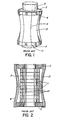
- This barrel stave projector contains a driver 1 formed of a stack of axially poled piezo-electric ceramic rings and an enclosure formed by a set of curved bars (staves) 2 with polygonal end plates 3.
- the staves 2 are secured to flat sides of the octagonal end plates 3 with an adhesive (epoxy resin) and bolts 4 retained in threaded holes in the end plates.
- Caps 6 and 7 cover openings in end plates 3.
- Axial motion of the stave ends is transformed to a larger radial motion of the staves midpoints.
- Slots 5 between the staves 2 are required to reduce the hoop stiffness and achieve a useful transformer ratio.
- Those slots 5 must be waterproofed by a rubber membrane (boot) that is stretched tightly around the projector and glued with epoxy.
- This boot 8 (shown in Figure 2) is used for sealing purposes and may be formed of a rubber membrane which, for variants designed for operation near 1kHz, is about 1 mm thick. It also provides corrosion protection for the Al staves used in these types of BSPs.
- the rubber membrane (boot) 8 which waterproofs the radiating surface of the BSP is, however, susceptible to chemical attack and degradation with resulting damage due to flooding through pinholes.
- BSPs also suffer from variation of performance with depth caused by water pressure forcing the rubber membrane into the slots between the vibrating staves of the projector unless a pressure compensation system is included.
- these BSPs exhibit non-linearity of performance versus drive voltage due to the effects of that rubber membrane.
- the present invention provides a one-piece slotless flextensional shell for an underwater acoustic projector which is inwardly concavely shaped similar to the BSP but which does not require any boot. It is formed of a one-piece shell with no gaps or openings in its outer surface. This shell achieves the required low hoop stiffness for low frequency operation by using folds rather than slots as used in the BSP.
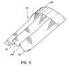
- This Folded Shell Projector's (FSP) surface is formed of a thin-walled one-piece inwardly concavely shaped shell containing corrugations (folds) running in the axial direction. The basic concept of such a FSP is illustrated in Figure 3 with one fold removed to show the inner piezoelectric driver 1'.
- the thin-walled folded shell 20 is inwardly concavely shaped with a number of axially extending corrugations having valleys 22 and ridges or cusps 24.
- the corrugations extend between end flanges 26 which are intended to be connected to end caps 3'.
- Leads 23 extend from the piezoelectric driver 1' through a central opening in one of the end caps 3'.
- Computer models of a slotless flextensional shell indicated that if aluminum (A1) was used as the shell material, then a wall thickness for practical designs would lie in the range of 1 to 2mm and that approximately 16 folds (corrugations) would provide the required performance.
- the depth of the corrugations varies from a maximum at the center to zero at the flange. The axial dependence of the depth of the fold is described by a polynomial of order N.
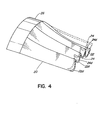
- Figure 4 is a view of the outside surface of a folded shell derived from a computer generated model showing deformation and axial/radial transformation action resulting from the force applied by an acoustic driver.
- Valleys 22 and cusp 24 show the shell 20 in an undeformed state whereas 22d and 24d shown shell 20 when deformed.
- a better termination for the fold's apex was considered to be in a radius as illustrated at 24r in Figure 5. This change would eliminate sharp edges on the outer wall which would have been hazardous to handle and easily damaged.
- This change to the cusps of the corrugations would result in a modest increase in shell mass and in the resonant frequency of the projector.
- Low-cost high volume production of these thin-walled FSP shells would generally be done by stamping a thin walled shell from non-ferrous or ferrous metals such as aluminum or steel, or by molding or by casting in plastics or composites such as metal-matrix or fiber-reinforced plastics.
- suitable metals or other materials from which a FSP may be manufactured with the best choices being ones that have low internal acoustic damping, high stiffness, low density and which can be readily formed and machined.
- a low cost version of a FSP could be made using injected molded thermosetting fiber reinforced plastic but the acoustic damping of that material would reduce the efficiency of the projector. This may be an acceptable trade-off for some applications.
- Aluminum alloys have been used with great success in BSP and would be a suitable material for forming a FSP.
- a protective coating on a metal FSP may be required for projectors which are exposed directly to sea water for long periods of time. Those protective coatings could be in the form of an anodised layer, an electroplated layer, paint, etc.
- electroforming was chosen as the most economical method to produce the thin-walled shell. Other production methods (stamping or molding) would have required the use of expensive dies and would not be practical for manufacturing one of a kind prototype shells.
- the choice of electroforming metals (Cr, Au, Ag, Cu, Ni) is rather limited and, of these, Ni was considered as a best choice since it is corrosion resistant, has high stiffness, high strength and low damping.
- a numerically controlled (NC) mill was programmed to make the required tooling which comprises a disposable hollow aluminum (A1) mandrel (upon which the Ni is plated), disposable Al plate endcaps with TeflonTM gaskets (to protect keyed ends of the mandrel from the plating process) and fixtures keyed to the mandrel and to the dividing head of the mill to permit accurate registration before and after plating.
- the outside surface of an aluminum cylinder was NC milled to the contours of the desired inside surface of the shell using standard ball nosed cutters to form the mandrel. That inside surface is inwardly concavely shaped with 16 corrugations running in the axial directions.
- the shell thickness was electroformed with Ni by plating onto the aluminum mandrel which produces a perfect replica of that outside surface to form the inside surface of the prototype FSD.
- the outside surface of that plated mandrel is irregular at this stage.
- the plated mandrel was reinstalled in the NC mill and the outside contours milled using chrome vanadium ball mills due tc the hardness of the Ni electroformed shell.
- the bulk of the Al mandrel was then bored out on a lathe with the resulting product, illustrated in Figure 6, having an Al hollow mandrel 30 and a Ni shell 20'.
- the remaining Al the remains of the mandrel, was then dissolved away in hot NaOH leaving only the Ni shell.
- That shell weighed 435.2 gm with a wall thickness of 1.27 mm at the midpoints of the folds.
- the axial compliance of the shell was measured to be 6.2 x 10 -9 ⁇ 1.0 x 10 -9 m/N using a dial indicator to measure axial deflections.
- the prototype FSP was completed using standard transducer construction techniques by inserting a fiberglass wrapped stack of 10 parallel connected axially poled piezo electric ceramic rings into the FSP prototype shell with two mild steel end plates, two aluminum endcaps and four 3.2 mm diameter stainless steel stress rods being assembled to complete the prototype.
- the ceramic rings have a smaller diameter than the minimum diameter of the prototype shell. This type of assembly is shown and described in U.S. Patent 4,922,470.
- the axially poled rings have a 50.8 mm o.d., a 38.1 mm i.d. and 10.1 mm thickness.
- the aluminum endcaps plug large access holes in the steel end plates.
- a cast epoxy gland was provided to waterproof the entry point for electrical leads, and air fittings were included for a pressure compensation system.
- the wall thickness measured at midpoints of the folds was found to be 1.27mm (+.05mm - .13mm). This agreed well with the selected desired wall thickness of 1.25mm.
- This shell's axial compliance was measured by compressing it in a hydraulic press to apply a known axial load. That measured value was 6.2 x 10 -9 ⁇ 1.0 x 10 -9 m/N.
- Table 2 summarizes the acoustic performance of the uncompensated prototype FSP obtained from shallow water (30m depth) calibration and some preliminary trials'in deep water.
- Resonant frequency 2100 Hz TVR 123.8 dB re 1 ⁇ Pa/V @ 1m SL (@ 3kV) 193.4 dB re 1 ⁇ Pa @ 1m Bandwidth 530 Hz Q 4.0 DI (at 2100 Hz) .98 G 24.5 ⁇ mho B 157.2 ⁇ mho Efficiency 65% Mass of complete projector 2.463 KG Figure of Merit 7.1 W/(Kg-kHz - Q) @ 3000V Depth Dependence of Resonant Frequency (uncompensated) 0.125 H Z /m (in 50-250m depth range).
- the relatively high resonance frequency (compared to a nominal 1100Hz for a BSP) reflects this prototype FSP transformer ratio and the shell compliance being lower than the corresponding values for a BSP. Suitable modification to the geometrical parameters can, however, reduce that resonant frequency.
- the TVR is equal to the best available BSP but if the design frequency is reduced, the TVR would be expected to decrease.
- the directivity was measured at resonance in two planes, the x-y and x-z planes. The quoted efficiency of 65% was estimated using the directivity index (DI) measured in the x-z plane, neglecting the effect of the smaller x-y plane directivity. If the directivity had been integrated over all angles, the resulting efficiency would be several percent higher.
- This FSP flextensional projector uses a one-piece thin walled metal shell as a radiating surface and achieves low tangential stiffness by using folds rather than the staves used in a BSP.
- This FSP one-piece shell is inherently watertight so that a rubber boot is not required which leads to reduced depth sensitivity, improved efficiency, increased thermal conductance to the surrounding fluid, higher reliability and better interelement matching than present BSPs.
- the prototype FSP was provided with a piezoelectric acoustic motor but other types of drive motors could be employed in a FSP.
- a magnetostrictive drive motor for instance, could be fitted into the space where the piezoelectric stack resided in the previously described prototype.
- Other types of acoustic drive motors that are suitable for use in FSPs include electrostrictive drive motors based on material such as PMN (lead metaniobate), electrodynamic drive motors (permanent magnet and coil) or hydroacoustic motors.
- the previously described prototype FSP contained 16 axially extending corrugations.
- the number of corrugations could, however, be varied anywhere from 8 corrugations upward to obtain optimum performance when different materials, wall thickness and geometry are used to produce a folded shell.
- Various types of geometry would be suitable for these types of FSPs.
- the radius of curvature R of the inwardly concave surface of the shell upon which the folds are superimposed may be, for instance, 5 to 20 times the radius of the flange and the maximum fold depth may be anywhere from 2 to 10 times the thickness of the shell wall.
- a variant of the known BSP described with respect to Figures 1 and 2 is described in U.S. Patent 5,135,556 by R.J. Obara wherein the staves are shaped and arranged to have a circular cross-section arrangement at the top and bottom of the BSP but an elliptical cross-sectional arrangement midway the top and bottom.
- Another variant of the known BSPs is a dual shell version developed by Dennis F. Jones to provide an increased bandwidth. That dual shell BSP is described by D.F. Jones and C.G.
- This dual shell BSP consists of 2 slightly different BSPs fastened together, end to end, to create a single unit having a wide bandwidth.
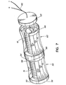
- This dual shell concept is also applicable to FSPs and one embodiment of a dual shell FSP is illustrated in Figure 7 wherein one quadrant is cut away and one end cap is separated to illustrate the interior.
- the dual shell FSP illustrated in Figure 7 is formed by a bottom shell 50 and top shell 60 which are joined together at flanges 58 and 68 secured to a central support plate 54 of approximately twice the thickness of the end caps 53, 63.
- a piezoelectric motor 51 is included inside shell 50 and a second piezoelectric motor 61 is included in shell 60 with the central divider 54 being located between the two motors.
- An end cap 53 hermetically seals the bottom of shell 50 while end cap 63 (shown separated) is used to seal the top end of shell 60, the end caps having a larger diameter than the piezoelectric motor.
- Electrical leads 65 for the motors extend through an opening in end cap 63 where an epoxy gland (not shown) is utilized for waterproofing.
- shell 50 and shell 60 are similar in shape to the prototype FSP but differ slightly such that the lowest breathing mode resonance frequencies are separated. When combined in the composite transducer, these two separated modal responses result in a broad bandwidth.
- the difference between the two shells 50 and 60 can be obtained by the shells having different lengths, wall thicknesses, radii of curvature, fold depths or a combination of these differences. Any one or combination of these parameters could be used to produce two separate resonances in the TVR with a useful flat region between them. This flat region provides an increased bandwidth over that which would be obtained from one of the shells.
- the preferred embodiments of the FSP have been described as ones specifically directed to underwater acoustic projectors but these FSPs can also be operated in air where they can operate as low frequency loudspeakers in, for instance, an alarm system.
- the one-piece shell will protect the acoustic driver from dust particles or other types of air supported pollutants which might exist in highly contaminated environments.
Landscapes
- Physics & Mathematics (AREA)
- Engineering & Computer Science (AREA)
- Acoustics & Sound (AREA)
- Multimedia (AREA)
- Transducers For Ultrasonic Waves (AREA)
- Transforming Electric Information Into Light Information (AREA)
- Piezo-Electric Transducers For Audible Bands (AREA)
- Non-Portable Lighting Devices Or Systems Thereof (AREA)
- Projection Apparatus (AREA)
Applications Claiming Priority (2)
| Application Number | Priority Date | Filing Date | Title |
|---|---|---|---|
| US08/932,581 US5805529A (en) | 1997-09-17 | 1997-09-17 | Folded shell projector (FSP) |
| US932581 | 1997-09-17 |
Publications (2)
| Publication Number | Publication Date |
|---|---|
| EP0903725A2 true EP0903725A2 (fr) | 1999-03-24 |
| EP0903725A3 EP0903725A3 (fr) | 2001-09-12 |
Family
ID=25462538
Family Applications (1)
| Application Number | Title | Priority Date | Filing Date |
|---|---|---|---|
| EP98307429A Withdrawn EP0903725A3 (fr) | 1997-09-17 | 1998-09-14 | Projecteur à coque pliée |
Country Status (4)
| Country | Link |
|---|---|
| US (1) | US5805529A (fr) |
| EP (1) | EP0903725A3 (fr) |
| AU (1) | AU741865B2 (fr) |
| CA (1) | CA2236370C (fr) |
Cited By (1)
| Publication number | Priority date | Publication date | Assignee | Title |
|---|---|---|---|---|
| WO2020205201A1 (fr) * | 2019-04-03 | 2020-10-08 | Raytheon Company | Transducteur en sablier amélioré |
Families Citing this family (22)
| Publication number | Priority date | Publication date | Assignee | Title |
|---|---|---|---|---|
| US6278658B1 (en) * | 1999-03-25 | 2001-08-21 | L3 Communications Corporation | Self biased transducer assembly and high voltage drive circuit |
| US6545949B1 (en) | 2001-09-21 | 2003-04-08 | Her Majesty The Queen In Right Of Canada, As Represented By The Minister Of National Defence | Axial drive resonant pipe projector (ADRPP) |
| US6643222B2 (en) * | 2002-01-10 | 2003-11-04 | Bae Systems Information And Electronic Systems Integration Inc | Wave flextensional shell configuration |
| US6535459B1 (en) * | 2002-04-18 | 2003-03-18 | Her Majesty The Queen In Right Of Canada, As Represented By The Minister Of National Defence In Her Brittanic Majesty's Government Of The United Kingdom Of Great Britain And Northern Ireland | Barrel stave projector-stave attachment |
| US6584039B1 (en) | 2002-06-17 | 2003-06-24 | Her Majesty The Queen In Right Of Canada, As Represented By The Minister Of National Defence | Multi-mode pipe projector |
| US6567343B1 (en) * | 2002-06-17 | 2003-05-20 | Her Majesty The Queen In Right Of Canada, As Represented By The Minister Of National Defence | Flextensional resonant pipe projector |
| US6567342B1 (en) * | 2002-07-17 | 2003-05-20 | Her Majesty The Queen In Right Of Canada, As Represented By The Minister Of National Defence | Flared wave-guide projector |
| US20050152222A1 (en) * | 2003-12-03 | 2005-07-14 | Rick Kaufman | Convex folded shell projector |
| WO2005062666A1 (fr) * | 2003-12-12 | 2005-07-07 | Bae Systems Information And Electronic Systems Integration Inc. | Projecteur acoustique et procede de fabrication |
| US7609586B2 (en) * | 2003-12-12 | 2009-10-27 | Bae Systems Information And Electronic Systems Integration Inc. | Acoustic projector having minimized mechanical stresses |
| CA2526309C (fr) * | 2004-12-21 | 2012-04-17 | Her Majesty In Right Of Canada As Represented By The Minister Of Nationa L Defence | Projecteur a basse frequence portatif |
| CA2538374C (fr) * | 2005-03-03 | 2013-11-19 | Her Majesty In Right Of Canada As Represented By The Minister Of National Defence | Projecteur a enveloppe pliee en mode de torsion |
| DE102006043027A1 (de) * | 2006-09-13 | 2008-03-27 | Epcos Ag | Verspannelement und Piezoaktor mit dem Verspannelement |
| US7573183B2 (en) * | 2007-09-19 | 2009-08-11 | Ricor Ltd. | Flextensional vibration-free pressure oscillator |
| JP5257277B2 (ja) * | 2009-07-03 | 2013-08-07 | 日本電気株式会社 | 音響トランスデューサ |
| JP5387293B2 (ja) * | 2009-09-29 | 2014-01-15 | 日本電気株式会社 | 音響トランスデューサ |
| JP5445323B2 (ja) * | 2010-05-17 | 2014-03-19 | 日本電気株式会社 | 音響トランスデューサ |
| US10473803B2 (en) * | 2013-02-08 | 2019-11-12 | Pgs Geophysical As | Marine seismic vibrators and methods of use |
| CN113301478B (zh) * | 2021-05-16 | 2024-08-02 | 西北工业大学 | 一种加筋式的凹筒型弯张换能器结构及方法 |
| GB2610816B (en) * | 2021-09-14 | 2023-11-01 | Thales Holdings Uk Plc | A stave, a flextensional transducer, and a water based sonar device |
| CN114979895B (zh) * | 2022-06-06 | 2023-01-24 | 哈尔滨工程大学 | 一种ⅰ型弯张换能器、工作方法及水下设备 |
| KR102915200B1 (ko) * | 2023-11-27 | 2026-01-20 | 국방과학연구소 | 다중공진 플렉스텐셔널 저주파 음향 프로젝터 |
Family Cites Families (6)
| Publication number | Priority date | Publication date | Assignee | Title |
|---|---|---|---|---|
| US4864548A (en) * | 1986-06-13 | 1989-09-05 | Image Acoustics, Inc. | Flextensional transducer |
| US4922470A (en) * | 1988-11-15 | 1990-05-01 | Her Majesty The Queen In Right Of Canada, As Represented By The Minister Of National Defence Of Her Majesty's Canadian Government | Barrel stave projector |
| US5030873A (en) * | 1989-08-18 | 1991-07-09 | Southwest Research Institute | Monopole, dipole, and quadrupole borehole seismic transducers |
| CA2032044A1 (fr) * | 1989-12-18 | 1991-06-19 | George H. Cavanagh, Iii | Transducteur a flexion a entrainement lateral |
| US5136556A (en) * | 1991-10-28 | 1992-08-04 | The Unites States Of America As Represented By The Secretary Of The Navy | Wide bandwidth barrel stave projector |
| FR2738704B1 (fr) * | 1995-09-08 | 1997-10-03 | Thomson Csf | Transducteur electroacoustique flextenseur |
-
1997
- 1997-09-17 US US08/932,581 patent/US5805529A/en not_active Expired - Fee Related
-
1998
- 1998-04-30 CA CA002236370A patent/CA2236370C/fr not_active Expired - Fee Related
- 1998-09-10 AU AU84175/98A patent/AU741865B2/en not_active Ceased
- 1998-09-14 EP EP98307429A patent/EP0903725A3/fr not_active Withdrawn
Cited By (5)
| Publication number | Priority date | Publication date | Assignee | Title |
|---|---|---|---|---|
| WO2020205201A1 (fr) * | 2019-04-03 | 2020-10-08 | Raytheon Company | Transducteur en sablier amélioré |
| US11417305B2 (en) | 2019-04-03 | 2022-08-16 | Raytheon Company | Enhanced hour-glass transducer |
| AU2020251869B2 (en) * | 2019-04-03 | 2024-12-19 | Raytheon Company | Enhanced hour-glass transducer |
| IL286856B2 (en) * | 2019-04-03 | 2025-04-01 | Raytheon Co | Improved hourglass transducer |
| AU2020251869C1 (en) * | 2019-04-03 | 2025-04-03 | Raytheon Company | Enhanced hour-glass transducer |
Also Published As
| Publication number | Publication date |
|---|---|
| CA2236370C (fr) | 2002-03-05 |
| CA2236370A1 (fr) | 1999-03-17 |
| AU741865B2 (en) | 2001-12-13 |
| EP0903725A3 (fr) | 2001-09-12 |
| US5805529A (en) | 1998-09-08 |
| AU8417598A (en) | 1999-04-01 |
Similar Documents
| Publication | Publication Date | Title |
|---|---|---|
| US5805529A (en) | Folded shell projector (FSP) | |
| WO1989009531A1 (fr) | Appareil de transduction electromecanique | |
| US4922470A (en) | Barrel stave projector | |
| US5130953A (en) | Submersible electro-acoustic transducer | |
| US4072871A (en) | Electroacoustic transducer | |
| AU775315B2 (en) | Bow dome sonar | |
| US6545949B1 (en) | Axial drive resonant pipe projector (ADRPP) | |
| CA2491829C (fr) | Systeme de projecteurs acoustiques sous-marins et methode de fabrication connexe | |
| US4972390A (en) | Stack driven flexural disc transducer | |
| US5508976A (en) | Low frequency underwater acoustic transducer | |
| US5229978A (en) | Electro-acoustic transducers | |
| US6584039B1 (en) | Multi-mode pipe projector | |
| US3972018A (en) | Electromechanical transducer | |
| GB2348774A (en) | Electro-acoustic transducers | |
| US6535459B1 (en) | Barrel stave projector-stave attachment | |
| US6567342B1 (en) | Flared wave-guide projector | |
| CA2431874C (fr) | Projecteur a tuyau resonnant flextensionnel | |
| CA2357605C (fr) | Guide d'ondes acoustique a generateur axial | |
| US3718897A (en) | High fidelity underwater misic projector | |
| NL8900961A (nl) | Elektro-acoustische omzetter met een buigzame en dichte uitzendende schaal. | |
| US6678213B1 (en) | Slotted cylinder transducer with trapezoidal cross-sectional electrodes | |
| Oswin et al. | Frequency, power and depth performance of class IV flextensional transducers | |
| Dufourcq et al. | Transducers for great depths | |
| Armstrong et al. | Discussion of the finite-element modelling and performance of ring-shell projectors | |
| Timme et al. | Transducer needs for low-frequency sonar |
Legal Events
| Date | Code | Title | Description |
|---|---|---|---|
| PUAI | Public reference made under article 153(3) epc to a published international application that has entered the european phase |
Free format text: ORIGINAL CODE: 0009012 |
|
| AK | Designated contracting states |
Kind code of ref document: A2 Designated state(s): AT BE CH CY DE DK ES FI FR GB GR IE IT LI LU MC NL PT SE Kind code of ref document: A2 Designated state(s): DE DK FR GB |
|
| AX | Request for extension of the european patent |
Free format text: AL;LT;LV;MK;RO;SI |
|
| PUAL | Search report despatched |
Free format text: ORIGINAL CODE: 0009013 |
|
| AK | Designated contracting states |
Kind code of ref document: A3 Designated state(s): AT BE CH CY DE DK ES FI FR GB GR IE IT LI LU MC NL PT SE |
|
| AX | Request for extension of the european patent |
Free format text: AL;LT;LV;MK;RO;SI |
|
| 17P | Request for examination filed |
Effective date: 20020226 |
|
| AKX | Designation fees paid |
Free format text: DE DK FR GB |
|
| 17Q | First examination report despatched |
Effective date: 20040112 |
|
| GRAP | Despatch of communication of intention to grant a patent |
Free format text: ORIGINAL CODE: EPIDOSNIGR1 |
|
| STAA | Information on the status of an ep patent application or granted ep patent |
Free format text: STATUS: THE APPLICATION IS DEEMED TO BE WITHDRAWN |
|
| 18D | Application deemed to be withdrawn |
Effective date: 20051213 |