EP0903698A2 - Aufnahme und/oder Wiedergabe von dreidimensionalen Bilddaten - Google Patents
Aufnahme und/oder Wiedergabe von dreidimensionalen Bilddaten Download PDFInfo
- Publication number
- EP0903698A2 EP0903698A2 EP98307498A EP98307498A EP0903698A2 EP 0903698 A2 EP0903698 A2 EP 0903698A2 EP 98307498 A EP98307498 A EP 98307498A EP 98307498 A EP98307498 A EP 98307498A EP 0903698 A2 EP0903698 A2 EP 0903698A2
- Authority
- EP
- European Patent Office
- Prior art keywords
- image
- information
- stream
- audio data
- data
- Prior art date
- Legal status (The legal status is an assumption and is not a legal conclusion. Google has not performed a legal analysis and makes no representation as to the accuracy of the status listed.)
- Ceased
Links
Images


Classifications
-
- H—ELECTRICITY
- H04—ELECTRIC COMMUNICATION TECHNIQUE
- H04N—PICTORIAL COMMUNICATION, e.g. TELEVISION
- H04N21/00—Selective content distribution, e.g. interactive television or video on demand [VOD]
- H04N21/20—Servers specifically adapted for the distribution of content, e.g. VOD servers; Operations thereof
- H04N21/23—Processing of content or additional data; Elementary server operations; Server middleware
-
- H—ELECTRICITY
- H04—ELECTRIC COMMUNICATION TECHNIQUE
- H04N—PICTORIAL COMMUNICATION, e.g. TELEVISION
- H04N21/00—Selective content distribution, e.g. interactive television or video on demand [VOD]
- H04N21/80—Generation or processing of content or additional data by content creator independently of the distribution process; Content per se
- H04N21/85—Assembly of content; Generation of multimedia applications
- H04N21/854—Content authoring
- H04N21/85406—Content authoring involving a specific file format, e.g. MP4 format
-
- H—ELECTRICITY
- H04—ELECTRIC COMMUNICATION TECHNIQUE
- H04N—PICTORIAL COMMUNICATION, e.g. TELEVISION
- H04N21/00—Selective content distribution, e.g. interactive television or video on demand [VOD]
- H04N21/20—Servers specifically adapted for the distribution of content, e.g. VOD servers; Operations thereof
- H04N21/23—Processing of content or additional data; Elementary server operations; Server middleware
- H04N21/234—Processing of video elementary streams, e.g. splicing of video streams or manipulating encoded video stream scene graphs
- H04N21/2343—Processing of video elementary streams, e.g. splicing of video streams or manipulating encoded video stream scene graphs involving reformatting operations of video signals for distribution or compliance with end-user requests or end-user device requirements
- H04N21/234309—Processing of video elementary streams, e.g. splicing of video streams or manipulating encoded video stream scene graphs involving reformatting operations of video signals for distribution or compliance with end-user requests or end-user device requirements by transcoding between formats or standards, e.g. from MPEG-2 to MPEG-4 or from Quicktime to Realvideo
-
- H—ELECTRICITY
- H04—ELECTRIC COMMUNICATION TECHNIQUE
- H04N—PICTORIAL COMMUNICATION, e.g. TELEVISION
- H04N21/00—Selective content distribution, e.g. interactive television or video on demand [VOD]
- H04N21/20—Servers specifically adapted for the distribution of content, e.g. VOD servers; Operations thereof
- H04N21/23—Processing of content or additional data; Elementary server operations; Server middleware
- H04N21/236—Assembling of a multiplex stream, e.g. transport stream, by combining a video stream with other content or additional data, e.g. inserting a URL [Uniform Resource Locator] into a video stream, multiplexing software data into a video stream; Remultiplexing of multiplex streams; Insertion of stuffing bits into the multiplex stream, e.g. to obtain a constant bit-rate; Assembling of a packetised elementary stream
-
- H—ELECTRICITY
- H04—ELECTRIC COMMUNICATION TECHNIQUE
- H04N—PICTORIAL COMMUNICATION, e.g. TELEVISION
- H04N21/00—Selective content distribution, e.g. interactive television or video on demand [VOD]
- H04N21/80—Generation or processing of content or additional data by content creator independently of the distribution process; Content per se
- H04N21/85—Assembly of content; Generation of multimedia applications
- H04N21/854—Content authoring
- H04N21/8543—Content authoring using a description language, e.g. Multimedia and Hypermedia information coding Expert Group [MHEG], eXtensible Markup Language [XML]
Definitions
- the present invention relates to producing three-dimensional space modelling data, processing such data, recording such data and recording a data processing program.
- Embodiments of the present invention relate to coding and decoding apparatus and method for recording a moving picture signal on a recording medium such as an optical disc or a magnetic tape and reproducing it for display on a display device.
- the embodiment of the present invention may be used in video conference systems, video telephone systems, broadcast equipment, multimedia database retrieval systems, and the like in such a manner that a moving picture signal is transmitted from a transmission side to a reception side via a transmission line and received and displayed on the reception side.
- the embodiments of the present invention may also be used for editing and recording a moving picture signal.
- an image signal is compressed/coded by utilizing line correlation or frame correlation of the video signal.
- a transmission line such as a network.
- a signal to be transmitted such as an image, sound, or computer data is transmitted after being compressed/coded.
- the compressed/coded signal that has been transmitted is decoded by a predetermined decoding method corresponding to the encoding method into an original image, sound, or computer data, which is output by a display device, speakers, or the like of the terminal.
- the transmitted image signal or the like was merely output, as it is, on a display device. But in information terminals using a computer, a plurality of images, sounds, or computer data can be handled or displayed in a two-dimensional or three-dimensional space after being subjected to a given conversion process.
- This type of process can be realized in such a manner that information of a two-dimensional or three-dimensional space is described by a given method on a transmission side, and the terminal side (reception side) executes a conversion process on an image signal or the like according to the description.
- VRML Virtual Reality Modeling Language
- ISO-IEC/JTC1/SC24 The latest version VRML 2.0 is described in IS14772.
- VRML is a language for describing a three-dimensional space and defines data for describing attributes, shapes, etc. of a three-dimensional space. Such data is called a node.
- Each node includes data indicating color, texture, etc., data indicating polygon shapes, and other information.
- a given object is generated by CG (computer graphics) according to a description of the above-mentioned VRML using polygons etc.
- VRML computer graphics
- a node called “Texture” is defined for still pictures and a node called “MovieTexture” is defined for moving pictures.
- Information (a file name, display start time or end time, etc.) on the texture to be attached is described in these nodes.
- a texture attachment process hereinafter referred to as a texture mapping process, where appropriate
- Fig. 23 shows an example of the configuration of texture mapping apparatus.
- a memory group 200 includes a texture memory 200a, a gray scale memory 200b, and a three-dimensional object memory 200c.
- the texture memory 200a stores texture information that is input externally.
- the gray scale memory 200b and the three-dimensional object memory 200c store key data indicating the degree of penetration/transparency of the texture and three-dimensional object information that are also input externally.
- the three-dimensional object information. is necessarv for qeneration of polygons and is related to illumination.
- a rendering circuit 201 generates a three-dimensional object by generating polygons based on the three-dimensional object information that is stored in the three-dimensional object memory 200c of the memory group 200.
- the rendering circuit 201 reads out the texture information and the key data indicating the degree of penetration/transparency of the texture from the memories 200a and 200b, respectively, and executes a superimposition process on the texture and a corresponding background image by referring to the key data.
- the key data indicates the degree of penetration of the texture at a corresponding position, that is, the transparency of an object at the corresponding position.
- a two-dimensional conversion circuit 202 outputs a two-dimensional image signal that is obtained by mapping the three-dimensional object that has been generated by the rendering circuit 201 to a two-dimensional plane based on view point information that is supplied externally. Where the texture is a moving picture, the above process is executed on a frame-by-frame basis.
- VRML With VRML, it is possible to handle, as texture information, data that has been compressed according to JPEG (Joint Photographic Experts Group) which is typically used in high-efficiency coding of a still picture, MPEG (Moving Picture Experts Group) for high-efficiency coding of a moving picture, or the like.
- JPEG Joint Photographic Experts Group
- MPEG Motion Picture Experts Group
- the texture (image) is decoded by a decoding process corresponding to an encoding scheme.
- the decoded image is stored in the texture memory 200a of the memory group 200 and subjected to a process similar to the above process.
- the rendering circuit 201 attaches the texture information that is stored in the texture memory 200a to an object at a given position regardless of the format of an image and whether the image is a moving picture or a still picture. Therefore, the texture that can be attached to a certain polygon is stored in one memory.
- transmitting three-dimensional object information it is necessary to transmit three-dimensional coordinates of each vertex. Real number data of 32 bits is needed for each coordinate component. Real number data of 32 bits or more is also needed for such attributes as reflection of each three-dimensional object. Therefore, information to be transmitted is enormous and further increases in transmitting a complex three-dimensional object or a moving picture. Therefore, in transmitting three-dimensional information as above or texture information via a transmission line, it is necessary to transmit compressed information for improving the transmission efficiency.
- MPEG Motion Picture Experts Group
- DCT discrete cosine transform
- An input image signal is first input to a frame memory 1, and then coded in a predetermined order.
- the image data to be coded is input to a motion vector detection circuit (ME) 2 on a macroblock basis.
- the motion vector detection circuit 2 processes image data of each frame as an I-picture, a P-picture, or a B-picture in accordance with a predetermined sequence. That is, it is predetermined whether images of respective frames that are input sequentially are processed as I, P, and B-pictures (for instance, they are processed in the order of I, B, P, B, P ..., B, P).
- the motion-vector detection circuit 2 performs motion compensation by referring to a predetermined reference frame and detects its motion vector.
- the motion compensation (interframe prediction) has three prediction modes, that is, forward prediction, backward prediction, and bidirectional prediction. Only forward prediction is available as a P-picture prediction mode, and three prediction modes, that is, forward prediction, backward prediction, and bidirectional prediction are available as a B-picture prediction mode.
- the motion vector detection circuit 2 selects a prediction mode that minimizes the prediction error and generates a corresponding prediction vector.
- the resulting prediction error is compared with, for instance, the variance of a macroblock to be coded. If the variance of the macroblock is smaller than the prediction error, no prediction is performed on the macroblock and intraframe coding is performed.
- the prediction mode is intra-image prediction (intra).
- a motion vector detected by the motion vector detection circuit 2 and the above-mentioned prediction mode are input to a variable-length coding circuit 6 and a motion compensation circuit (MC) 12.
- the motion compensation circuit 12 generates prediction image data based on a given motion vector and inputs it to operation circuits 3 and 10.
- the operation circuit 3 calculates difference data indicating a difference between the value of the macroblock to be coded and the value of the prediction image data and outputs a calculation result to a DCT circuit 4. In the case of an intra-macroblock mode, the operation circuit 3 outputs, as it is, the macroblock data to be coded to the DCT circuit 4.
- the DCT circuit 4 converts the input data into DCT coefficients by subjecting the data to DCT (discrete cosine transform).
- the DCT coefficients are input to a quantization circuit (Q) 5, where they are quantized with a quantization step corresponding to a data storage amount (buffer storage amount) of a transmission buffer 7.
- Quantized coefficients (data) are input to the variable-length coding circuit 6.
- the variable-length coding circuit 6 converts quantized data that is supplied from the quantization circuit 5 into a variable-length code such as a Huffman code.
- the variable-length coding circuit 6 also receives the quantization step (scale) from the quantization circuit 5 and the prediction mode (indicating which of intra-image prediction, forward prediction, backward prediction, and bidirectional prediction was set) and the motion vector from the motion vector detection circuit 2, and performs variable length coding thereon.
- the transmission buffer 7 temporarily stores received coded data and outputs a quantization control signal that corresponds to the storage amount to the quantization circuit 5. When the residual data amount has increased to the allowable upper limit, the transmission buffer 7 controls to reduce the data amount of quantization data by increasing the quantization scale of the quantization circuit 5 using the quantization control signal.
- the transmission buffer 7 controls to increase the data amount of quantization data by decreasing the quantization scale of the quantization circuit 5 using the quantization control signal. Overflow or underflow of the transmission circuit 7 is prevented in this manner.
- Coded data stored in the transmission buffer 7 is read out with predetermined timing and output as a bit stream to a transmission line.
- quantized data that is output from the quantization circuit 5 is input to a de-quantization circuit (IQ) 8, where it is de-quantized in accordance with a quantization step supplied from the quantization circuit 5.
- IQ de-quantization circuit
- Output data (DCT coefficients) from the de-quantization circuit 8 is input to an IDCT (inverse DCT) circuit 9, then subjected to inverse DCT processing, and stored in a frame memory (FM) 11 via the operation circuit 10.
- IDCT inverse DCT
- a decoder image signal decoding apparatus
- MP@ML of MPEG Coded image data (bit stream) that has been transmitted via a transmission line is received by a receiving circuit (not shown), or reproduced by a reproduction circuit, temporarily stored in a reception buffer 21, and then supplied to a variable-length decoding circuit (IVLC) 22.
- IVLC variable-length decoding circuit
- the variable-length decoding circuit 22 outputs a motion vector and a prediction mode to a motion compensation circuit 27 and a quantization step to a de-quantization circuit 23. Further, the variable-length decoding circuit 22 outputs decoded quantized data to the de-quantization circuit 23.
- the de-quantization circuit 23 de-quantizes the quantized data that is supplied from the variable-length decoding circuit 22 in accordance with the quantization step also supplied from the variable-length decoding circuit 22, and outputs the resulting data (DCT coefficients) to an IDCT circuit 24.
- the data (DCT coefficients) that is output from the de-quantization circuit 23 is subjected to inverse DCT in the IDCT circuit 24 and supplied to an operation circuit 25 as output data. If the output data supplied from the IDCT circuit 24 (the input bit stream) is I-picture data, it is output from the operation circuit 25 as image data and then supplied to a frame memory 26 and stored there for generation of prediction image data for image data (P or B-picture data) that will be input to the operation circuit 25. This image data is also output, as it is, to the external system as a reproduction image.
- the motion compensation circuit 27 If the output data supplied from the IDCT circuit 24 (the input bit stream) is a P or B-picture, the motion compensation circuit 27 generates a prediction image based on the image data stored in the frame memory 26 in accordance with the motion vectbr and the prediction mode that are supplied from the variable-length decoding circuit 22, and outputs it to the operation circuit 25.
- the operation circuit 25 adds the output data that is supplied from the IDCT circuit 24 and the prediction image data that is supplied from the motion compensation circuit 27, to produce output image data.
- the output data of the operation circuit 25 is input to the frame memory 26 and stored there as prediction image data (a reference image) for an image signal to be subsequently decoded.
- MPEG various profiles and levels other than MP@ML are defined and various tools are prepared. Scalability is one of those tools.
- the scalable coding scheme is introduced that realizes scalability for accommodating different image sizes and frame rates.
- an image signal having a small image size can be decoded by decoding only lower-layer bit streams, and an image signal having a large image size can be decoded by decoding lower-layer and upper-layer bit streams.
- An encoder of spatial scalability will be described with reference to Fig. 26.
- the lower layer corresponds to image signals having a small image size
- the upper layer corresponds to image signals having a large size.
- a lower-layer image signal is first input to the frame memory 1 and then coded in the same manner as in the case of MP@ML.
- the output of the operation circuit 10 supplied to the frame memory 11 used as a lower-layer prediction image data, but also it is used as an upper-layer prediction image data after being enlarged to the same image size as the upper-layer image size by an image enlargement circuit (up sampling) 31.
- an upper-layer image signal is input to a frame memory 51.
- a motion vector detection circuit 52 determines a motion vector and a prediction mode in the same manner as in the case of MP@ML.
- a motion compensation circuit 62 generates prediction image data in accordance with the motion vector and the prediction mode that have been determined by the motion vector detection circuit 52 and outputs it to a weighting circuit (W) 34.
- the weighting circuit 34 multiplies the prediction image data by a weight W and outputs the weighted prediction image data to an operation circuit 33.
- output data (image data) of the operation circuit 10 is input to the image enlargement circuit 31.
- the image enlargement circuit 31 enlarges the image data that has been generated by the operation circuit 10 to make its size equal to the upper-layer image size and outputs the enlarged image data to a weighting circuit (1-W) 32.
- the weighting circuit 32 multiplies the enlarged image data of the image enlargement circuit 31 by a weight (1-W) and outputs the result to the operation circuit 33.
- the operation circuit 33 adds the output data of the weighting circuits 32 and 34 and outputs the result to an operation circuit 53 as a prediction image data.
- the output data of the operation circuit 33 is also input to an operation circuit 60, added to output data of an inverse DCT circuit 59 there, and then input to a frame memory 61 for later use as a prediction image data for image data to be coded.
- the operation circuit 53 calculates a difference between the output data of the image data to be coded and the output data of the operation circuit 33, and outputs the result as difference data.
- the operation circuit 53 outputs, as it is, the image data to be coded to a DCT circuit 54.
- the DCT circuit 54 performs DCT (discrete cosine transform) on the output of the operation circuit 53, to generate DCT coefficients, which are output to a quantization circuit 55.
- the quantization circuit 55 quantizes the DCT coefficients in accordance with a quantization scale that is based on the data storage amount of a transmission buffer 57 and other factors, and outputs a result (quantized data) to a variable-length coding circuit 56.
- the variable-length coding circuit 56 performs variable-length coding on the quantized data (quantized DCT coefficients) and outputs a result as an upper-layer bit stream via the transmission buffer 57.
- the output data of the quantization circuit 55 is de-quantized by a de-quantization circuit 58 with the quantization scale that was used in the quantization circuit 55, subjected to inverse DCT in the inverse DCT circuit 59, and then input to the operation circuit 60.
- the operation circuit 60 adds the outputs of the operation circuit 33 and the inverse DCT circuit 59 and inputs a result to the frame memory 61.
- the variable-length coding circuit 56 also receives the motion vector and the prediction mode that were detected by the motion vector detection circuit 52, the quantization scale that was used in the quantization circuit 55, and the weights W that were used in the weighting circuits 32 and 34, which are coded in the variable-length coding circuit 56 and then transmitted.
- a lower-layer bit stream is input to the reception buffer 21 and then decoded in the same manner as in the case of MP@ML.
- the output of the operation circuit 25 output to the external system and stored in the frame memory 26 for use as a prediction image data for an image signal to be decoded later, but also it is used as an upper-layer prediction image data after being enlarged to the same image size as an upper-layer image size by an image signal enlargement circuit 81.
- An upper-layer bit stream is supplied to a variable-length decoding circuit 72 via a reception buffer 71, and a variable-length code is decoded there.
- a quantization scale, a motion vector, a prediction mode, and a weighting coefficient (weight W) are decoded together with DCT coefficients.
- the DCT coefficients (quantized data) decoded by the variable-length decoding circuit 72 are de-quantized by a de-quantization circuit 73 by using the decoded quantization scale, subjected to inverse DCT in an inverse DCT circuit 74, and then supplied to an operation circuit 75.
- a motion compensation circuit 77 generates predictior. image data in accordance with the decoded motion vector and prediction mode and inputs it to a weighting circuit 84.
- the weighting circuit 84 multiplies the output of the motion compensation circuit 77 by the decoded weight W and outputs a result to an operation circuit 83. Not only is the output of the operation circuit 25 supplied as lower-layer reproduction image data and output to the frame memory 26, but also it is output to a weighting circuit 82 after being enlarged by the image signal enlargement circuit 81 so as to have the same image size as the upper-layer image size.
- the weighting circuit 82 multiplies the output of the image signal enlargement circuit 81 by (1 - W) by using the decoded weight W, and outputs the result to the operation circuit 83.
- the operation circuit 83 adds the outputs of the weighting circuits 82 and 84 and outputs the result to the operation circuit 75.
- the operation circuit 75 adds the output of the inverse DCT circuit 74 and the output of the operation circuit 83, and outputs the result as upper-layer reproduction image data and also supplies it to the frame memory 76 for use as prediction image data for image data to be decoded later.
- the above description is applied to a process for a luminance signal.
- a color difference signal is processed in a similar manner.
- the motion vector to be used in processing a color difference signal is obtained by halving a motion vector for a luminance signal in both vertical and horizontal directions.
- H.261 and H.263 are a combination of motion-compensation predictive coding and DCT coding.
- a coding apparatus and a decoding apparatus according to H.261 or H.263 are configured in the same manner as in the MPEG scheme though the details of header information etc. are different. Further, in the above-described MPEG scheme, the standardization of a new highly efficient coding scheme called MPEG4 is now underway.
- MPEG4 Major features of MPEG4 are that an image is coded on an object-by-object basis (an image is coded in units of a plurality of images) and that the image can be modified on the object-by-object basis. That is, on the decoding side, images of respective objects or a plurality of images can be combined to reconstruct one image.
- the description of a scene (hereinafter abbreviated as a scene description), the description of a three-dimensional object, and AV data consisting of a moving image, sound or audio compressed according to the MPEG scheme, which have been obtained in the above manner, are given time stamps and multiplexed by a multiplexing circuit into a bit stream, which is transmitted as multiplexed bit stream.
- a demultiplexing circuit extracts the scene description, the description of a three-dimensional object, and AV stream (a stream corresponding to AV data), decoders decode respective bit streams, and a scene that is reconstructed by a scene construction circuit is displayed on a display device.
- VRML assumes a model in which a client requests information.
- MPEG assumes a model in which broadcast information or the like is transmitted under the control of a server. The difference in these models causes a problem that it is difficult to fuse together a computer graphics image and a natural image while compatibility with VRML2.0 is maintained.
- An embodiment of the present invention seeks to enable a computer graphics image that is described according to VRML and an image or the like that is compressed according to the MPEG scheme to be transmitted in such a state that they are multiplexed into the same bit (data) stream.
- a method for producing three dimensional space modeling data defined by a plurality of nodes and image/audio data specified by a position included in the nodes the following steps are carried out: extracting a respective position from a node of the three dimensional space modeling data; converting the extracted position into a stream ID corresponding to image/audio data associated with the position; replacing the position with the stream ID; and multiplexing the image/audio data and three dimensional space modeling data including the stream ID to produce a bit stream.
- the three dimensional space modeling data is described by Virtual Reality Modeling Language (VRML), the position is represented by Uniform Resource Locator (URL) expressed in ASCII format, and the stream ID is expressed in binary format.
- VRML Virtual Reality Modeling Language
- URL Uniform Resource Locator
- the stream ID is converted into a character string, and it is determined whether to replace the position of the image/audio data with the stream ID or the character string depending on whether the image/audio data is supplied by one server or multiple servers.
- Fig. 1 is a block diagram of a first embodiment of coding apparatus according to the present invention.
- a system control circuit 301 receives a request signal (Request (REQ)), determines, by referring to a scene description SD (the details will be described later) what is stored in a storage device 302, what AV object (three-dimensional object, natural image, sound, or the like) should be transmitted, and outputs a scene request signal (Scene Request (SREQ)) to the storage device 302.
- the storage device 302 stores the scene description SD that describes a two-dimensional or three-dimensional scene.
- the scene description SD is described according to an ASCII format that complies with VRML2.0.
- a storage device 306 stores Audio and Video (AV) data bit stream (elementary streams (ES)) such as a moving picture, still picture, and sound.
- AV Audio and Video
- ES elementary streams
- a storage device 305 stores information (object stream info (OI)) necessary for decoding AV objects stored in the storage device 306.
- the object stream information OI is a buffer size necessary for decoding an AV object, or a time stamp of each access unit.
- the object stream information OI includes all information of AV bit stream corresponding to the respective AV objects.
- a relationship among a scene description, AV data (streams), and three-dimensional objects will be described below with reference to Fig. 2.
- a rectangular image sequence and a triangular pyramid generated by computer graphics are displayed on the screen 352.
- no texture is attached to the triangular pyramid, a texture may be attached to it as in the case of other three-dimensional objects.
- a texture to be added may be either a still picture or a moving picture.
- the scene description SD 350 comprises descriptions called nodes.
- a node SD1 which is a child node of the parent node SD0, describes information relating to the triangular pyramid.
- the image signal comprises three video objects VO (background, sun, and person).
- the Node SD2 describes information relating to the background.
- the node SD3 describes information relating to the rectangular plane for attachment of the sun.
- the node SD4 describes information relating to the plane for attachment of the person.
- Each node describes a URL that indicates an address of the corresponding AV data (bit stream) file.
- the nodes SD3 and SD4 are child nodes of the node SD2.
- the single scene description SD is a collection of all the nodes SD0-SD4.
- a collection of descriptions of all nodes is called a scene description and the respective nodes are called objects (two-dimensional or three-dimensional objects). Therefore, each node corresponds to a single two-dimensional or three-dimensional object.
- Each object corresponds, one to one, to an object descriptor OD that describes AV data (bit stream) relating to the object.
- a parsing circuit 307 reads out a URL (indicating the address of an AV data file) described in a node that is output from the storage device 302, and outputs, to the storage device 306, a request signal (ES Request (ESREQ)) for requesting output of AV data (bit stream) corresponding to the URL. Further, the parsing circuit 307 outputs, to the storage device 305, a request signal (OI Request (OIREQ)) for requesting output of object stream information OI that describes information relating to the AV data (bit stream) corresponding to the URL.
- ES Request ESREQ
- OI Request OIREQ
- An OD (object descriptor) generation circuit 304 receives object stream information OI relating to an AV object that is output from the storage device 305, and extracts, as an object descriptor OD, only information of AV data (bit stream) that was requested by a request signal OIREQ and outputs it to a multiplexing circuit 303. Further, the OD generation circuit 304 generates an ID number OD_ID for each extracted object descriptor OD, records it in the object descriptor OD and outputs the resulting object descriptor OD to the multiplexing circuit 303, and also outputs the generated ID number ID_OD to a BIFS encoder 308.
- the BIFS encoder 308 converts the scene description of an ASCII format that is output from the storage device 302 into a binary format, and replaces a URL included in the scene description SD with ID number OD_ID that is output from the OD generation circuit 304. And then, the BIFS encoder 308 outputs the scene description B-SD that has been converted into a binary format and replaced with the ID number OD_ID to the multiplexing circuit 303.
- the multiplexing circuit 303 multiplexes, in prescribed order, AV data (bit stream) stored in the storage device 306, the scene description B-SD that has been converted into a binary format by the BIFS encoder 308, and the object descriptors OD that have been generated by the OD generation circuit 304, and outputs the multiplexed result as a multiplexing bit stream FS.
- AV data bit stream
- BIFS encoder 308 the scene description B-SD that has been converted into a binary format by the BIFS encoder 308
- object descriptors OD that have been generated by the OD generation circuit 304
- a request signal REQ is supplied to the scene control circuit 301.
- the scene control circuit 301 determines what AV object should be transmitted by referring to the scene description SD that is stored in the storage device 302 based on the request signal REQ, and outputs a scene request signal SREQ to the storage device 302.
- the storage device 302 reads out the corresponding scene description SD (described in an ASCII format) and supplies it to the parsing circuit 307 and the BIFS encoder 308.
- Fig. 3 shows an example of a scene description SD (described in the ASCII format) for attachment of a moving picture as a texture.
- a URL indicating the address of a moving picture file to be attached is described on the sixth line.
- Fig. 4 shows an example of a scene description SD (described in the ASCII format) for attachment of a still picture as a texture.
- a URL indicating the address of a still picture file to be attached is described on the second line.
- the formats of Figs. 3 and 4 comply with the node description of VRML.
- the parsing circuit 307 reads out a URL (indicating the address of AV data (bit stream) file) included in a node that constitutes the supplied scene description SD, and outputs a request signal ESREQ to the storage device 306. As a result, the corresponding AV data (bit stream) ES is output from the storage device 306 and supplied to the multiplexing circuit 303.
- the parsing circuit 307 outputs, to the storage device 305, a request signal OIREQ for requesting output of object stream information OI relating to the AV data (bit stream) ES indicated by the URL that is included in the node.
- a request signal OIREQ for requesting output of object stream information OI relating to the AV data (bit stream) ES indicated by the URL that is included in the node.
- the object stream information OI corresponding to the URL is output from the storage device 305 to the OD generation circuit 304.
- the OD generation circuit 304 extracts, as an object descriptor OD, only the information requested by the request signal OIREQ from the object stream information OI relating to the AV object that is supplied from the storage device 305. Further, the OD generation circuit 304 generates an ID number OD_ID, records it in the object descriptor OD, and outputs the resulting object descriptor OD to the multiplexing circuit 303. Still further, the OD generation circuit 304 outputs the ID number OD_ID that has been generated for each object descriptor OD to the BIFS encoder 308.
- the BIFS encoder 308 converts the scene description SD of an ASCII format that is supplied from the storage circuit 302 into data (a scene description B-SD) of a binary format by a predetermined method and replaces URL included in the scene description SD. And then, the BIFS encoder 308 outputs to the multiplexing circuit 303 the scene description B-SD that has been converted to the binary format.
- the details of the binary format are described in the document called MPEG4WD (document number N1825) that has been standardized by ISO. An example of the binary format will be described below.
- Fig. 5 shows data obtained by converting a scene description (ASCII format; see Fig. 3) for attaching a moving picture as a texture into a binary format.
- "ObjectDescriptorID" appearing on the 29th line is a flag indicating ID number OD_ID of a moving picture to be attached to this node.
- the BIFS encoder 308 writes ID number OD_ID that is supplied from the OD generation circuit 304 in this portion in the scene description B-SD that has been converted into the binary format.
- ID number AV data bit stream
- ID number OD_ID binary format
- Fig. 6 shows data that is obtained by converting a scene description (ASCII format; see Fig. 4) for attaching a still picture as a texture into a binary format.
- ASCII format see Fig. 4
- Fig. 4 "ObjectDescriptorID” appears on the 17th line and ID number OD_ID is written in this portion in the scene description B-SD that has been converted into the binary format.
- the scene description B-SD of a binary format thus generated is supplied to the multiplexing circuit 303.
- the multiplexing circuit 303 multiplexes, in prescribed order, AV data (bit stream) stored in the storage device 306, the scene description B-SD that has been converted into a binary format by the BIFS encoder 308, and the object descriptors OD that have been generated by the OD generation circuit 304, and outputs the multiplexing bit stream FS.
- Fig. 7 shows an example of a detailed configuration of the multiplexing circuit 303.
- a start code generation circuit 303a generates and outputs a start code that indicates a start position of a bit stream.
- AV data (bit stream) ES1-ESN that are output from the storage device 306 are supplied to corresponding terminals.
- the multiplexing circuit 303 operates a switch so as to make a connection to the terminal to which the start code generation circuit 303a is connected, to thereby output the start code.
- switching is made to the terminal to which the scene description SD is input, whereby the scene description SD is output.
- switching is made to the terminal to which the object descriptors OD are input, whereby the object descriptors OD are output.
- switching is made sequentially, in accordance with the data, to the terminals to which the AV data (bit stream) are input, whereby the AV data (bit stream) ES1-ESN are output.
- the multiplexing circuit 303 selects the start code, the scene description SD, the object descriptors OD, and the AV data (bit stream) with the switch, and thereby outputs those to the external system as a multiplexed bit stream FS.
- the multiplexed bit stream FS is supplied to a reception terminal via a transmission line, for example.
- Fig. 8 is a block diagram showing an example of the configuration of an embodiment of a decoding apparatus according to the invention.
- a demultiplexing circuit 404 receives a multiplexed bit stream FS and then separates and extracts respective bit streams that constitute the multiplexed bit stream FS.
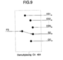
- Fig. 9 shows an example of configuration of the demultiplexing circuit 404.
- the demultiplexing circuit 404 detects a start code in the multiplexed bit stream FS and recognizes a presence of the respective bit streams. And then, an input multiplexed bit stream FS is separated, with a switch, into a stream description SD and object descriptors OD which are output from corresponding terminals. Similarly, bit streams ES1-ESN of AV data are separated and output from corresponding terminals.
- a parsing circuit 406 receives the object descriptors OD that have been separated by the demultiplexing circuit 404, determines the kind and the number of decoders that are necessary for decoding the AV data (bit stream), and causes the bit streams of the respective AV data (bit stream) to be supplied to corresponding decoders. Further, the parsing circuit 406 reads out buffer capacities necessary for decoding the respective bit streams from the object descriptors OD, and supplies those (Init) to the respective decoders 407-409.
- the parsing circuit 406 outputs ID numbers OD_ID of respective object descriptors to the decoders that are to decode the bit streams described in the respective object descriptors OD.
- the decoders 407-409 decode the bit streams according to a predetermined decoding method and corresponding to the encoding method, and output resulting video data or audio/sound data to a reconstruction circuit 411. Further, the decoders 407-409 output, to the reconstruction circuit 411, ID numbers OD_ID indicating what nodes the respective decoded data (video data or audio (sound) data) belong to.
- the decoders 407-409 decode, from the bit stream, the data (SZ, POS) indicating the size and display position of the image (image size and display position data) and data (key data) indicating the degree of penetration of the image, and output that data to the reconstruction circuit 411.
- a parsing circuit 410 parses the scene description B-SD of the binary format and supplies the resulting data to the reconstruction circuit 411. Further, the parsing circuit 410 reads ID numbers OD_ID in the scene description B-SD that corresponds to the ID numbers OD_ID in the object descriptors and supplies those to the reconstructing circuit 411.
- Fig. 10 shows a relationship among bit streams to reconstruct an entire image and an example of the reconstruction circuit 411.
- the reconstruction circuit 411 comprises a synthesizing circuit 351; and an image signal that is produced by the synthesizing circuit 351 is supplied to a display device 352 and thereby the image is displayed there.
- the synthesizing circuit 351 and the display device 352 are shown as the reconstruction circuit 411. This is to show how the image that has been produced at the synthesizing circuit 351 is displayed in the display device 251. Actually the display device 352 is not included in the reconstruction circuit 209.
- the synthesizing circuit 351 receives the node data and ID number OD_ID that is supplied from the parse circuit 410 and the image data, the key data, the image size and display position information (SZ, POS), and ID numbers OD_ID that are supplied from the decoders 407-409, captures the image data corresponding to OD_ID, attaches the image data to the nodes based on the key data and the size and display position information, and outputs image signals corresponding to resulting image data to the display device 352.
- Fig. 11 is a block diagram showing an example of the reconstruction circuit 411.
- the reconstruction circuit 411 comprises a matching circuit 360, object synthesizing circuits 500-502 and a two-dimensional conversion circuit 503.
- the object synthesizing circuit 500 comprises a memory group 500-1 and a rendering circuit 500-2.
- the memory group 500-1 comprises atexture memory 500-1a, a gray scale memory 500-1b, and a three-dimensional object memory 500-1c.
- the texture memory 500-la stores AV data (bit stream) that is supplied from the decoder 407 as texture data.
- the gray scale memory 500-1b stores key data indicating the degree of penetration that is supplied from the decoder 407.
- the three-dimensional object memory 500-1c stores three-dimensional object information (node) that is output from the parsing circuit 410.
- the three-dimensional object information (node) includes polygon forming information, illumination information for illumination of polygons, and other information.
- the image size and display position data (SZ, POS) is also stored in a certain location, for example, the gray scale memory 500-1b.
- the rendering circuit 500-2 generates a three-dimensional object using polygons based on the node stored in the three-dimensional object memory 500-1c. Further, the rendering circuit 500-2 receives the texture and the key data indicating the degree of penetration from the texture memory 500-1a and the gray scale memory 500-1b, respectively, attaches the texture to the corresponding node, and executes a process corresponding to the key data so that the texture has the preselected transparency. The data thus obtained are output to the two-dimensional conversion circuit 503. Further, the image size and display position data (SZ, POS) is output to the two-dimensional conversion circuit 503. Since the object synthesizing circuits 501 and 502 are configured in the same manner as the object synthesizing circuit 500, they are not described here.
- the texture (the image data) is attached (mapped) to the object
- the ID numbers OD_ID described in the object descriptors OD and the ID numbers OD_ID described in the scene description B-SD are used. Therefore, the data that has been output to the reconstruction circuit 411 is first supplied to the matching circuit 360 before the data is supplied to the corresponding object synthesizing circuits 500-502.
- the ID numbers OD_ID described in the object descriptors OD are matched with the ID numbers OD_ID described in the scene description B-SD by a matching circuit 360 as shown in Fig. 8; and the relationship is found thereby.
- the two-dimensional conversion circuit 503 converts, in accordance with view point information that is supplied externally and the image size and display position data that supplied from the object synthesizing circuits, the texture-attached objects that are output from the respective object synthesizing circuits 500-502 into a two-dimensional image signal through mapping to a two-dimensional plane.
- the resulting two-dimensional image signal is supplied to the display device 352 for display thereon.
- a multiplexed bit stream FS that has been transmitted via a transmission line is supplied to the demultiplexing circuit 404.
- the demultiplexing circuit 404 detects the start code in the multiplexed bit stream FS and also recognizes bit streams.
- the demultiplexing circuit 404 separates a scene description B-SD, and object descriptors OD, bit streams ES1-ESN corresponding to AV data (bit stream) from the multiplexed bit stream FS and outputs those by properly switching the switch shown in Fig. 9.
- the object descriptors OD are supplied to the parsing circuit 406, the bit streams ES1-ESN are supplied to the respective decoders 407-409, and the scene description B-SD of the binary format is supplied to the parsing circuit 410.
- the parsing circuit 410 parses the scene description B-SD of the binary format that is output from the demultiplexing circuit 404 and supplies a result (three dimensional object information (NODE)) to the reconstruction circuit 411. Further, the parsing circuit 410 decodes ID numbers OD_ID of object descriptors OD of AV data (bit stream) to be attached to the nodes, and supplies those to the reconstruction circuit 411.
- NODE three dimensional object information
- the parsing circuit 406 receives the object descriptors OD, recognizes the kind and the number of decoders necessary for decoding the bit streams, and causes the bit streams ES1-ESN to be supplied to the respective decoders. Further, the parsing circuit 406 reads out buffer capacities or a time stamp of each access unit necessary for decoding the respective bit streams from the object descriptors OD, and supplies those as an initialization information (Init) to the respective decoders 407-409. As a result, the decoders 407-409 perform initialization by referring to the supplied values (the initialization information (Init)). Further, to indicate what objects the bit streams that have been processed by the respective decoders 407-409 belong to, the parsing circuit 406 outputs the ID numbers OD_ID of the respective object descriptors.
- the decoders 407-409 perform initialization such as securing of a buffer in accordance with the initialization information that is supplied from the parsing circuit 406.
- the decoders 407-409 decode the respective bit streams by a predetermined method corresponding to the encoding operation, and outputs resulting video data or audio (sound) data to the reconstruction circuit 411.
- the decoders 407-409 output, to the reconstruction circuit 411, ID numbers OD_ID indicating what objects the bit streams that have been decoded by the respective decoders correspond to. Still further, if the decoded bit stream is an image, the decoders 407-409 output data indicating the size and display position of the image (SZ, POS) and data (key data) indicating the degree of penetration of the image.
- data that has been output to the reconstruction circuit 411 is supplied to the corresponding object synthesizing circuits 500-502.
- One object synthesizing circuit corresponds to each node.
- the ID numbers OD_ID described in the object descriptors OD are collated (matched) by the matching circuit 360 with the ID numbers OD_ID described in the scene description B-SD before the data is supplied to the corresponding object synthesizing circuits.
- the object synthesizing circuits 500-502 receive the decoded signal including ID numbers OD_ID that are indicated by the nodes from the decoders 407-409, respectively. If the received decoded signal is image data, the object synthesizing circuits 500-502 attach the image to a two-dimensional or three-dimensional object to be generated.
- the texture data to be attached to the object is stored in the texture memory 500-1a.
- the key data and ID number OD_ID are supplied to the gray scale memory 500-1b and stored there.
- the node (three-dimensional object information) is stored in the three-dimensional object memory 500-1c.
- the image size and display position data (SZ, POS) is also stored in a certain location, for example, the gray scale memory 500-1b.
- ID number OD_ID is used to recognize the node.
- the rendering circuit 500-2 reads out the node (three-dimensional object information) that is stored in the three-dimensional object memory 500-1c and generates a corresponding object by using polygons. Further, the rendering circuit 500-2 attaches the image data that is received from the texture memory 500-1a to the above-generated polygons by referring to the key data indicating the degree of penetration that is received from the gray scale memory 500-1b. Further, image size and display position data (SZ, POS) is read out from the gray scale memory 500-1b and supplied to the two-dimensional conversion circuit 503. Similar operations are performed by the object synthesizing circuits 501 and 502.
- the two-dimensional conversion circuit 503 is supplied with the texture-attached two-dimensional or three-dimensional objects from the object synthesizing circuits 500-502. Based on view point information that is supplied externally and the image size and display position data (SZ, PCS), the two-dimensional conversion circuit 503 converts the three-dimensional objects into a two-dimensional image signal through mapping to a two-dimensional plane. The three-dimensional objects that have been converted into the two-dimensional image signal are output (displayed) on the display device 352.
- the outputs of the respective rendering circuits 500-2 to 502-2 are combined as they are in accordance with their degree of penetration (key data), and then output. In this case, no conversion is performed.
- Figs. 12-14 show structures of an object descriptor OD.
- Fig. 12 shows the entire structure of the object descriptor OD.
- "NodeId” on the third line is a 10-bit flag indicating the ID number of this descriptor, and corresponds to the above-mentioned ID number OD_ID.
- Item “streamCount” on the fourth line is an 8-bit flag indicating the number of AV data units (bit streams ES) included in the object descriptor OD. Therefore, items "ES_Descriptor” that are necessary for decoding the respective bit streams ES are transmitted in a number that is indicated by "streamCount.”
- Item “extensionFlag” on the fifth line is a flag indicating whether to transmit other information. If the value of this flag is "1", other descriptors are transmitted.
- ES_Descriptor on the eighth line is a descriptor indicating information relating to each bit stream.
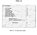
- Fig. 13 shows details of "ES_Descriptor.”
- ES_number on the third line is a 5-bit flag indicating an ID number for identification of the bit stream.
- Item "StreamType” on the 6th line indicates the format of the bit stream and, for instance, is an 8-bit flag indicating such data as an MPEG2 video.
- Item "QOS_Descriptor” is an 8-bit flag indicating a request to a network in a transmission.
- Item “ESConfigParams” on the 8th line is a descriptor that describes information necessary for decoding of the bit stream, and its details are shown in Fig. 14. The details of "ESConfigParams" are described in MPEG4 System.
- a URL that is included in a node that constitutes three-dimensional space modeling data (VRML data) is replaced by the ID number OD_ID of an object descriptor OD corresponding to AV data (bit stream) that is designated by the URL.
- an object descriptor OD corresponding to ID number QD_ID that is included in a node is searched for (collated), whereby corresponding data AV data (bit stream) is detected (recognized). Therefore, it becomes possible to transmit a CG image and a natural image that are multiplexed into the same stream while the method of describing a scene and a three-dimensional object is kept compatible with, for instance, the VRML scheme.
- coded audio and video data are stored in the storage device 306.
- they may be input directly from an audio or video coding apparatus without passing through such a storage device.
- AV data bit stream
- object descriptors OD object descriptors OD
- scene description SD scene description SD
- AV data bit stream
- object stream information OI may be generated on a real time basis at the time of transmission.
- a URL changing circuit 309 is added to the embodiment of Fig. 1.
- the output data from the parsing circuit 307 and the output from the OD generation circuit 304 are supplied to the URL changing circuit 309, and then the output data from the URL changing circuit 309 is supplied to the BIFS encoder 308.
- the remaining configuration is the same as in the embodiment of Fig. 1.
- the URL changing circuit 309 converts ID number OD_ID that is output from the OD generation circuit 304 into a corresponding character string of an ASCII format, and then outputs it. For example, a description will be made of an example in which object stream information OI that is necessary for decoding AV data (bit stream) to be attached to a certain node stored in the storage device 302 has the following address. http://serverA/AV_scenel/object_file.1
- object stream information OI is read out from the storage device 305, and ID number OD_ID of an object descriptor OD corresponding to the object stream information OI is supplied from the OD generation circuit 304.
- the URL changing circuit 309 receives the ID number OD_ID and rewrites (changes) the URL to an appropriate character string of the ASCII format. For example, if OD_ID is "4", Expression (1) is rewritten (changed) to the following. mpeg4://4
- a URL described in a node that is stored in the storage device 302 designates a file existing in coding apparatus (on the network) that is different from the coding apparatus of Fig. 15.
- the URL changing circuit 309 stops the conversion operation, and the URL of Expression (1), for instance, is supplied, as it is, to the BIFS encoder 308.
- the scene control circuit 301 determines what AV object should be transmitted by referring to a scene description SD that is stored in the storage device 302 based on the request signal REQ, and outputs a scene request signal SREQ to the storage device 302.
- the storage device 302 When receiving the scene request signal SREQ, the storage device 302 reads out a corresponding scene description SD (described in the ASCII format) and supplies it to the parsing circuit 307 and the BIFS encoder 308.
- a corresponding scene description SD described in the ASCII format
- the parsing circuit 307 reads out a URL (indicating the address of an AV data (bit stream) file) included in a node that constitutes the supplied scene description SD, and outputs, to the storage device 306, a request signal ESREQ for output of AV data (bit stream) corresponding to the URL.
- a request signal ESREQ for output of AV data (bit stream) corresponding to the URL.
- the corresponding AV data (bit stream) ES is output from the storage device 306 and supplied to the multiplexing circuit 303.
- the parsing circuit 307 outputs, to the storage device 305, a request signal OIREQ for requesting output of object stream information OI relating to the AV data (bit stream) ES, indicated by the URL that is included in the node.
- a request signal OIREQ for requesting output of object stream information OI relating to the AV data (bit stream) ES, indicated by the URL that is included in the node.
- the object stream information OI corresponding to the URL is output from the storage device 305 and supplied to the OD generation circuit 304.
- the parsing circuit 307 outputs to the URL changing circuit 309, the URL that is included in the node.
- the OD generation circuit 304 extracts, as an object descriptor OD, only the object stream information requested by the OIREQ from the object stream information OI relating to the AV object that is supplied from the storage circuit 305. Further, the OD generation circuit 304 generates an ID number OD_ID, records it in the object descriptor OD, and outputs the resulting object descriptor OD to the multiplexing circuit 303. Still further, the OD generation circuit 304 outputs the ID number OD_ID that has been generated for each object descriptor OD to the URL changing circuit 309.
- the URL changing circuit 309 If the URL that has been supplied from the parsing circuit 307 designates a file existing in another server on the network, the URL changing circuit 309 outputs, as it is, the URL to the BIFS encoder 308. If the supplied URL designates an AV data (bit stream) file stored in the storage device 306, the URL changing circuit 309 generates a character string such as that of Expression (2) by referring to ID number OD_ID that is output from the OD generation circuit 304, and outputs the character string to the BIFS encoder 308.
- the BIFS encoder 308 converts the scene description SD of an ASCII format that is supplied from the storage device 302 into a scene description B-SD of a binary format by a predetermined method and replaces the URL included in the scene description SD with the URL or the character string supplied from the OD generation circuit 304. Thereafter, the scene description B-SD of the binary format is output to the multiplexing circuit 303.
- Fig. 16 shows an example of a scene description SD in binary format for attachment of a moving picture as a texture.
- a URL on the 29th line is a character string of an ASCII format that is output from the URL changing circuit 309. That is, in this embodiment, a URL is described as a character string in binary format.
- Fig. 17 shows an example of a binary format of a scene description SD for attachment of a still picture as a texture.
- a URL on the 17th line of Fig. 17 is a character string of an ASCII format.
- the scene descriptor SD that has been converted into a binary format by the BIFS encoder 308 is supplied to the multiplexing circuit 303, and multiplexed with the object descriptors OD and the AV data (bit stream) ES.
- the resulting multiplexed bit stream FS is output from the multiplexing circuit 303.
- the multiplexed bit stream FS is supplied to decoding apparatus via a transmission line, for example.
- Fig. 18 is a block diagram showing a second embodiment of decoding apparatus according to the invention.
- the portions corresponding to the portions in Fig. 8 are given the same reference symbols as the latter and will not be described.
- a URL conversion circuit 412 is added to the embodiment of Fig. 8. Further, a parsing circuit 410 supplies information that is expressed as a character string of ASCII format. The remaining configuration is the same as in the embodiment of Fig. 8.
- the URL changing circuit 412 converts the information expressed as a character string of ASCII format into ID number OD_ID that is the ID of a corresponding object descriptor OD, and supplies it to the reconstruction circuit 411.
- the URL that has been extracted from a node by the parsing circuit 410 is supplied to the URL conversion circuit 412. If the URL is a character string having, for instance, a format of Expression (2), the URL conversion circuit 412 converts the character string into ID number OD_ID and supplies it to the reconstruction circuit 411. As a result, the reconstruction circuit 411 attaches corresponding AV data as a texture to the node based on the ID number OD-ID included in the node.
- the URL changing circuit 412 supplies the information to the demultiplexing circuit 404, and then the demultiplexing circuit 404 issues a file transmission request to that server.
- a multiplexed bit stream FS' is transmitted through execution of a similar process, and a display operation is performed.
- the desired AV data can be acquired and displayed.
- FIG. 19 is a block diagram showing the third embodiment of the coding apparatus according to the invention.
- those portions having corresponding portions in Fig. 1 are given the same reference symbols as the latter and will not be described.
- a URL changing circuit 309, a switch 310, and a control circuit 311 are added to the embodiment of Fig. 1. Further, the output data from the parsing circuit 307 and the ID number OD_ID from the OD generation circuit 304 are supplied to the URL changing circuit 309. The output data from the URL changing circuit 309 and ID number OD_ID from the OD generation circuit 304 are supplied to the switch 310, and the control circuit 311 controls the switch 310.
- the remaining configuration is the same as in the embodiment of Fig. 1.
- the URL changing circuit 309 converts ID number OD_ID that is output from the OD generation circuit 304 into a corresponding character string of ASCII format and outputs it. Since the operation of the URL changing circuit 309 was described in the second embodiment of Fig. 15, it is not described here.
- the switch 310 selects one of ID number OD_ID that is output from the OD generation circuit 304 and the URL that is output from the URL changing circuit 309, and outputs the selected OD_ID or URL to the BIFS encoder 308.
- the control circuit 311 controls the switching of the switch 310 in accordance with the type of application, for instance. Next, the operation of this embodiment will be described briefly.
- a URL whose format has been converted by the URL changing circuit 309 (the details are explained in the second embodiment and will not be described here) is supplied to the switch 310.
- ID number QD_ID that has been output from the OD generation circuit 304 is supplied to the switch 310.
- the connection of the switch 310 is changed under the control of the control circuit 311.
- ID number OD_ID be directly described as a numeral in the form of, for instance, a 10-bit flag rather than a character string. Therefore, in such an application, the switch 310 is controlled by the control circuit 311 so as to select the output data from the OD generation circuit 304, in which case ID number OD_ID is recorded in a scene description B-SD of binary format by the BIFS encoder 308.
- control circuit 311 controls the switch 310 to change its connection so that the output data from the URL changing circuit 309 is selected, whereby the URL is output to and recorded by the BIFS encoder 308.
- the switch 310 is controlled so as to make a connection to the URL changing circuit 309, whereby a URL is recorded in a scene description B-SD of binary format by the BIFS encoder 308.
- Fig. 20 shows an example of binary format of a scene description B-SD for attachment of a moving picture as a texture.
- “isString” on the 29th and 30th lines is a 1-bit flag indicating whether ID number OD_ID or a URL is described. If this value is "0”, ID number OD_ID of 10 bits is recorded in the node. If the value of "isString" is "1", a URL is recorded.
- the URL is a character string that has been rewritten by the URL changing circuit 309 so as to indicate ID number OD_ID of a moving picture to be attached to the node.
- Fig. 20 shows an example of a binary format of a scene description B-SD for attachment of a still picture as a texture.
- "isString" on the 17th and 18th lines is a 1-bit flag indicating whether ID number OD ID or a URL is described.
- a multiplexed stream FS that has been coded by the above coding apparatus is transmitted to decoding apparatus via a transmission line.
- Fig. 22 is a block diagram showing the third embodiment of decoding apparatus corresponding to the coding apparatus of Fig. 19 according to the invention.
- those portions having corresponding portions in Fig. 8 are given the same reference symbols as the latter and will not be described further.
- a URL conversion circuit 412 is added to the embodiment of Fig. 8.
- the remaining configuration is the same as in the embodiment of Fig. 8.
- the parsing circuit 410 decodes "isString”. If this value is “1”, the parsing circuit 410 supplies a URL to the URL conversion circuit 412. If this value is "0”, the parsing circuit 410 decodes ID number OD_ID and supplies a result to the reconstruction circuit 411.
- the URL conversion circuit 412 decodes ID number OD_ID and outputs a result to the reconstruction circuit 411. If the URL indicates a file existing in another server, the information is supplied to the demultiplexing circuit 404 and the demultiplexing circuit 404 accesses that server and reads out the desired file.
- a read-out scene description SD (node) is supplied to the parsing circuit 410 and analyzed therein.
- the parsed scene description is supplied to the reconstruction circuit 411. Further, the parsing circuit 410 decodes "isString” and judges whether its value is "1". If this value is judged to be "1", the parsing circuit 410 supplies the URL conversion circuit 412 with a URL of AV data (bit stream) to be attached, as a texture, to the node.
- the URL conversion circuit 412 decodes ID number OD_ID that is the ID of an object descriptor OD from the character strings and outputs it to the reconstruction circuit 411. If the URL designates a file existing in another server, the information is supplied to the demultiplexing circuit 404 and the demultiplexing circuit 404 accesses that server, requests the server to transfer the desired file, and receives it. Even when communication is made with a plurality of servers, each server operates in the same manner as described above.
- the parsing circuit 410 decodes ID number OD_ID and outputs a result to the reconstruction circuit 411. The remaining operation is the same as in the first embodiment and is not described hereinbelow.
- the most appropriate coding method can be selected in accordance with the type of application.
- a recording medium such as a disc, DVD-R, CD-R, CD-ROM, etc.
- the method and apparatus may be implemented on a multi-purpose (general) computer being programmed for this use.
- the recording medium or other storage device may contain operating instructions (program source code or software) to perform each of the steps set forth in the methods for encoding and decoding operations as noted hereinabove.
- a transmission channel connected to a communications network or the like may be provided to receive and transmit data from an encoder, and to decode the encoded data.
- the illustrative encoding and decoding apparatus and illustrative method in accordance with the invention may be employed for encoding and decoding information from a digital video disc, a picture data base, picture compression and expansion units, a picture downloaded from the Internet, or software modules implementing these systems, by way of example.
- three-dimensional space modeling data (VRML data) is input and data (AV data stream) are also input.
- a location indication data (URL) included in a node of the input three-dimensional space modeling data (VRML data) is extracted.
- the extracted location indication data (URL) is converted into a stream ID corresponding to data (AV data stream) designated by the location indication data (URL).
- the location indication data (URL) of the node is replaced by the stream ID obtained by the conversion.
- Three-dimensional space modeling data (VRML data) obtained by the replacement and the AV data are multiplexed into the same stream. Therefore, it becomes possible to transmit an object that is described as three-dimensional space modeling data (VRML data) and a natural image that is compressed according to, for instance, the MPEG scheme in a state that they are multiplexed into the same stream.
- nodes are extracted from multiplexed data and data (AV data (bit stream)) are extracted from the multiplexed data.
- Information indicating a correlation between the nodes and the data is extracted from the nodes.
- the nodes are collated (matched) with the data (AV data (bit stream)) based on the extracted information indicating the correlation.
- the nodes and the data (AV data (bit stream)) are combined based on a correlation result. Therefore, it becomes possible to decode data that has been transmitted in a state that an object that is described as three-dimensional space modeling data (VRML data) and a natural image that is compressed according to, for instance, the MPEG scheme are multiplexed into the same data stream.
- VRML data three-dimensional space modeling data
Landscapes
- Engineering & Computer Science (AREA)
- Multimedia (AREA)
- Signal Processing (AREA)
- Computer Security & Cryptography (AREA)
- Compression Or Coding Systems Of Tv Signals (AREA)
- Two-Way Televisions, Distribution Of Moving Picture Or The Like (AREA)
- Processing Or Creating Images (AREA)
- Testing, Inspecting, Measuring Of Stereoscopic Televisions And Televisions (AREA)
- Television Systems (AREA)
- Image Processing (AREA)
- Television Signal Processing For Recording (AREA)
Applications Claiming Priority (3)
| Application Number | Priority Date | Filing Date | Title |
|---|---|---|---|
| JP27519697 | 1997-09-22 | ||
| JP275196/97 | 1997-09-22 | ||
| JP27519697 | 1997-09-22 |
Publications (2)
| Publication Number | Publication Date |
|---|---|
| EP0903698A2 true EP0903698A2 (de) | 1999-03-24 |
| EP0903698A3 EP0903698A3 (de) | 2000-05-17 |
Family
ID=17552031
Family Applications (1)
| Application Number | Title | Priority Date | Filing Date |
|---|---|---|---|
| EP19980307498 Ceased EP0903698A3 (de) | 1997-09-22 | 1998-09-16 | Aufnahme und/oder Wiedergabe von dreidimensionalen Bilddaten |
Country Status (9)
| Country | Link |
|---|---|
| US (1) | US6611262B1 (de) |
| EP (1) | EP0903698A3 (de) |
| JP (2) | JPH11177946A (de) |
| KR (1) | KR100563013B1 (de) |
| CN (2) | CN1247029C (de) |
| AU (1) | AU761202B2 (de) |
| CA (1) | CA2247594C (de) |
| IL (6) | IL175071A0 (de) |
| SG (1) | SG89267A1 (de) |
Cited By (3)
| Publication number | Priority date | Publication date | Assignee | Title |
|---|---|---|---|---|
| WO2000043959A3 (en) * | 1999-01-22 | 2000-11-30 | Lego As | Virtual reality modelling |
| US6389375B1 (en) | 1999-01-22 | 2002-05-14 | Interlego Ag | Virtual reality modelling |
| EP1134702A3 (de) * | 2000-03-14 | 2003-10-29 | Samsung Electronics Co., Ltd. | Verfahren zur Verarbeitung von Knoten in dreidimensionaler Szene und dessen Gerät |
Families Citing this family (78)
| Publication number | Priority date | Publication date | Assignee | Title |
|---|---|---|---|---|
| US6934906B1 (en) | 1999-07-08 | 2005-08-23 | At&T Corp. | Methods and apparatus for integrating external applications into an MPEG-4 scene |
| KR100353843B1 (ko) * | 1999-12-24 | 2002-09-26 | 한국전자통신연구원 | 인터넷에서의 3차원 데이터 저장 및 검색 방법 |
| US7685534B2 (en) * | 2000-02-16 | 2010-03-23 | Jlb Ventures Llc | Method and apparatus for a three-dimensional web-navigator |
| JP2001243043A (ja) * | 2000-02-29 | 2001-09-07 | Sony Corp | ユーザインタフェースシステム、シーン記述生成装置及び方法、シーン記述変換装置及び方法、記録媒体並びに伝送媒体 |
| KR100374797B1 (ko) * | 2000-03-14 | 2003-03-03 | 삼성전자주식회사 | 삼차원 장면의 노드를 처리하는 방법 및 그 장치 |
| KR100429838B1 (ko) * | 2000-03-14 | 2004-05-03 | 삼성전자주식회사 | 인터랙티브 멀티미디어 콘텐츠 서비스에서 업스트림채널을 이용한 사용자 요구 처리방법 및 그 장치 |
| FR2806570B1 (fr) * | 2000-03-15 | 2002-05-17 | Thomson Multimedia Sa | Procede et dispositif de codage d'images video |
| FR2807268A1 (fr) * | 2000-04-04 | 2001-10-05 | Koninkl Philips Electronics Nv | Reseau, terminal d'emission et methode de constitution d'un point d'acces dans un flux de donnees |
| JP2002064802A (ja) * | 2000-08-21 | 2002-02-28 | Sony Corp | データ伝送システム、データ伝送装置及び方法、シーン記述処理装置及び方法 |
| JP2002232841A (ja) * | 2000-11-10 | 2002-08-16 | Satake Corp | マルチメディア情報処理装置 |
| US7500017B2 (en) * | 2001-04-19 | 2009-03-03 | Microsoft Corporation | Method and system for providing an XML binary format |
| FR2823942A1 (fr) * | 2001-04-24 | 2002-10-25 | Koninkl Philips Electronics Nv | Dispositif pour une conversion d'un format bifs textuel vers un format bifs binaire |
| KR100424762B1 (ko) * | 2001-09-06 | 2004-03-30 | 삼성전자주식회사 | 영상 데이터 제공 시스템 및 방법 |
| KR100491956B1 (ko) * | 2001-11-07 | 2005-05-31 | 경북대학교 산학협력단 | 엠펙(mpeg)-4 컨텐츠 생성 방법 및 그 장치 |
| KR20030065001A (ko) * | 2002-01-29 | 2003-08-06 | 주식회사 리코시스 | Mpeg-4 데이터 편집장치 및 편집방법 |
| US8421804B2 (en) | 2005-02-16 | 2013-04-16 | At&T Intellectual Property Ii, L.P. | System and method of streaming 3-D wireframe animations |
| WO2004036955A1 (en) | 2002-10-15 | 2004-04-29 | Electronics And Telecommunications Research Institute | Method for generating and consuming 3d audio scene with extended spatiality of sound source |
| KR100626661B1 (ko) * | 2002-10-15 | 2006-09-22 | 한국전자통신연구원 | 공간성이 확장된 음원을 갖는 3차원 음향 장면 처리 방법 |
| EP1445954A1 (de) * | 2003-02-10 | 2004-08-11 | Thomson Licensing S.A. | Verfahren zur Übertragung und zum Empfangen von Schriftarteninformationen in Streaming-Systemen |
| US7142602B2 (en) * | 2003-05-21 | 2006-11-28 | Mitsubishi Electric Research Laboratories, Inc. | Method for segmenting 3D objects from compressed videos |
| US7978716B2 (en) | 2003-11-24 | 2011-07-12 | Citrix Systems, Inc. | Systems and methods for providing a VPN solution |
| US7617531B1 (en) * | 2004-02-18 | 2009-11-10 | Citrix Systems, Inc. | Inferencing data types of message components |
| US7983835B2 (en) | 2004-11-03 | 2011-07-19 | Lagassey Paul J | Modular intelligent transportation system |
| US7821516B2 (en) * | 2004-05-17 | 2010-10-26 | Pixar | Automatic pre-render pinning of change isolated assets methods and apparatus |
| KR20050117826A (ko) * | 2004-06-11 | 2005-12-15 | 삼성전자주식회사 | 디지털 오디오 방송에서 인터랙티브 정보를 포함하는슬라이드 쇼 제공방법, 처리장치 및 dab 수신장치 |
| US8495305B2 (en) | 2004-06-30 | 2013-07-23 | Citrix Systems, Inc. | Method and device for performing caching of dynamically generated objects in a data communication network |
| US8739274B2 (en) | 2004-06-30 | 2014-05-27 | Citrix Systems, Inc. | Method and device for performing integrated caching in a data communication network |
| US7757074B2 (en) | 2004-06-30 | 2010-07-13 | Citrix Application Networking, Llc | System and method for establishing a virtual private network |
| CN101023637B (zh) * | 2004-07-22 | 2010-12-29 | 韩国电子通信研究院 | 简单聚合格式同步层分组结构及其服务器系统 |
| EP2264956B1 (de) | 2004-07-23 | 2017-06-14 | Citrix Systems, Inc. | Verfahren zur sicherung von zugriff aus der ferne auf private netze |
| US9219579B2 (en) | 2004-07-23 | 2015-12-22 | Citrix Systems, Inc. | Systems and methods for client-side application-aware prioritization of network communications |
| US7348982B2 (en) | 2004-09-30 | 2008-03-25 | Microsoft Corporation | Method, system, and computer-readable medium for creating and laying out a graphic within an application program |
| US8510657B2 (en) | 2004-09-30 | 2013-08-13 | Microsoft Corporation | Editing the text of an arbitrary graphic via a hierarchical list |
| US8134575B2 (en) | 2004-09-30 | 2012-03-13 | Microsoft Corporation | Maintaining graphical presentations based on user customizations |
| US8549149B2 (en) | 2004-12-30 | 2013-10-01 | Citrix Systems, Inc. | Systems and methods for providing client-side accelerated access to remote applications via TCP multiplexing |
| US8700695B2 (en) | 2004-12-30 | 2014-04-15 | Citrix Systems, Inc. | Systems and methods for providing client-side accelerated access to remote applications via TCP pooling |
| US8954595B2 (en) | 2004-12-30 | 2015-02-10 | Citrix Systems, Inc. | Systems and methods for providing client-side accelerated access to remote applications via TCP buffering |
| US7810089B2 (en) * | 2004-12-30 | 2010-10-05 | Citrix Systems, Inc. | Systems and methods for automatic installation and execution of a client-side acceleration program |
| US8706877B2 (en) | 2004-12-30 | 2014-04-22 | Citrix Systems, Inc. | Systems and methods for providing client-side dynamic redirection to bypass an intermediary |
| KR20070104566A (ko) | 2005-01-24 | 2007-10-26 | 사이트릭스 시스템스, 인크. | 네트워크에서 동적으로 발생된 객체들의 캐싱을 수행하는시스템 및 방법 |
| US8255456B2 (en) | 2005-12-30 | 2012-08-28 | Citrix Systems, Inc. | System and method for performing flash caching of dynamically generated objects in a data communication network |
| KR100612890B1 (ko) * | 2005-02-17 | 2006-08-14 | 삼성전자주식회사 | 3차원 이미지의 다중 특수 효과 표현 방법 및 장치 |
| KR100785012B1 (ko) | 2005-04-11 | 2007-12-12 | 삼성전자주식회사 | 3d 압축 데이터 생성, 복원 방법 및 그 장치 |
| EP1869773A4 (de) * | 2005-04-11 | 2009-03-11 | Samsung Electronics Co Ltd | Verfahren und vorrichtungen zum erzeugen und wiederherstellen von 3d-kompressionsdaten |
| WO2007043830A1 (en) * | 2005-10-13 | 2007-04-19 | Lg Electronics Inc. | Method and apparatus for encoding/decoding |
| US7921184B2 (en) | 2005-12-30 | 2011-04-05 | Citrix Systems, Inc. | System and method for performing flash crowd caching of dynamically generated objects in a data communication network |
| US8301839B2 (en) | 2005-12-30 | 2012-10-30 | Citrix Systems, Inc. | System and method for performing granular invalidation of cached dynamically generated objects in a data communication network |
| US8438486B2 (en) | 2006-02-09 | 2013-05-07 | Microsoft Corporation | Automatically converting text to business graphics |
| EP2001235B1 (de) * | 2007-06-08 | 2013-05-22 | Samsung Electronics Co., Ltd. | MPEG-4 Format-Erweiterung zum Aufzeichnen von stereoskopischen oder synthetischen 3D Videodaten mit zusammenhängenden Metadaten. |
| KR100955578B1 (ko) * | 2007-12-18 | 2010-04-30 | 한국전자통신연구원 | 스테레오스코픽 콘텐츠 장면 재생 방법 및 그 장치 |
| US8624898B1 (en) | 2009-03-09 | 2014-01-07 | Pixar | Typed dependency graphs |
| JP5573316B2 (ja) * | 2009-05-13 | 2014-08-20 | セイコーエプソン株式会社 | 画像処理方法および画像処理装置 |
| WO2011082647A1 (zh) * | 2010-01-07 | 2011-07-14 | Dong futian | 空间数据渐进传输方法及装置 |
| US8799325B2 (en) | 2010-03-12 | 2014-08-05 | Microsoft Corporation | Reordering nodes in a hierarchical structure |
| US8908103B2 (en) * | 2010-10-01 | 2014-12-09 | Sony Corporation | Content supplying apparatus, content supplying method, content reproduction apparatus, content reproduction method, program and content viewing system |
| JP5793871B2 (ja) * | 2011-01-25 | 2015-10-14 | ソニー株式会社 | 受信装置、受信方法、供給装置、供給方法、プログラム、および放送システム |
| CN102819851B (zh) * | 2012-08-08 | 2015-03-18 | 成都思珩网络科技有限公司 | 一种有声图片的计算机实现方法 |
| US9171401B2 (en) | 2013-03-14 | 2015-10-27 | Dreamworks Animation Llc | Conservative partitioning for rendering a computer-generated animation |
| US9224239B2 (en) | 2013-03-14 | 2015-12-29 | Dreamworks Animation Llc | Look-based selection for rendering a computer-generated animation |
| US9514562B2 (en) | 2013-03-15 | 2016-12-06 | Dreamworks Animation Llc | Procedural partitioning of a scene |
| US9208597B2 (en) | 2013-03-15 | 2015-12-08 | Dreamworks Animation Llc | Generalized instancing for three-dimensional scene data |
| US9626787B2 (en) | 2013-03-15 | 2017-04-18 | Dreamworks Animation Llc | For node in render setup graph |
| US9589382B2 (en) | 2013-03-15 | 2017-03-07 | Dreamworks Animation Llc | Render setup graph |
| US9218785B2 (en) | 2013-03-15 | 2015-12-22 | Dreamworks Animation Llc | Lighting correction filters |
| US9230294B2 (en) | 2013-03-15 | 2016-01-05 | Dreamworks Animation Llc | Preserving and reusing intermediate data |
| US9811936B2 (en) * | 2013-03-15 | 2017-11-07 | Dreamworks Animation L.L.C. | Level-based data sharing for digital content production |
| US9659398B2 (en) | 2013-03-15 | 2017-05-23 | Dreamworks Animation Llc | Multiple visual representations of lighting effects in a computer animation scene |
| CN105578172B (zh) * | 2015-12-10 | 2017-12-05 | 四川长虹电器股份有限公司 | 基于Unity3D引擎的裸眼3D视频显示方法 |
| MY190934A (en) * | 2015-12-14 | 2022-05-23 | Panasonic Ip Corp America | Three-dimensional data encoding method, three-dimensional data decoding method, three-dimensional data encoding device, and three-dimensional data decoding device |
| US10297087B2 (en) * | 2017-05-31 | 2019-05-21 | Verizon Patent And Licensing Inc. | Methods and systems for generating a merged reality scene based on a virtual object and on a real-world object represented from different vantage points in different video data streams |
| EP3834153A1 (de) | 2018-08-10 | 2021-06-16 | NVIDIA Corporation | Plattform und verfahren zur kollaborativen erzeugung von inhalten |
| US12100112B2 (en) | 2018-08-10 | 2024-09-24 | Nvidia Corporation | Cloud-centric platform for collaboration and connectivity on 3D virtual environments |
| CN110099242A (zh) * | 2019-04-02 | 2019-08-06 | 视联动力信息技术股份有限公司 | 一种远程直播方法和装置 |
| CN112995766B (zh) * | 2019-12-12 | 2023-10-10 | 天翼数字生活科技有限公司 | 用于标识iptv多路视频流的方法和装置 |
| US20210105451A1 (en) * | 2019-12-23 | 2021-04-08 | Intel Corporation | Scene construction using object-based immersive media |
| US20220134222A1 (en) * | 2020-11-03 | 2022-05-05 | Nvidia Corporation | Delta propagation in cloud-centric platforms for collaboration and connectivity |
| US11797475B2 (en) * | 2021-01-14 | 2023-10-24 | Tencent America LLC | Method and apparatus for media scene description |
| WO2022241119A1 (en) | 2021-05-12 | 2022-11-17 | Qualcomm Incorporated | Split rendering of extended reality data over 5g networks |
Family Cites Families (7)
| Publication number | Priority date | Publication date | Assignee | Title |
|---|---|---|---|---|
| JP3658797B2 (ja) * | 1995-06-16 | 2005-06-08 | ソニー株式会社 | 情報通信装置及び情報提供装置 |
| CA2180899A1 (en) | 1995-07-12 | 1997-01-13 | Yasuaki Honda | Synchronous updating of sub objects in a three dimensional virtual reality space sharing system and method therefore |
| CA2180891C (en) | 1995-07-12 | 2010-01-12 | Junichi Rekimoto | Notification of updates in a three-dimensional virtual reality space sharing system |
| JP3859018B2 (ja) * | 1995-07-12 | 2006-12-20 | ソニー株式会社 | 3次元仮想現実空間共有方法、3次元仮想現実空間共有システム、アドレス管理方法、並びにアドレス管理サーバ端末 |
| JP3702525B2 (ja) * | 1996-03-06 | 2005-10-05 | 株式会社日立製作所 | インタラクティブ映像記録再生方式 |
| JP4726096B2 (ja) * | 1997-04-07 | 2011-07-20 | エイ・ティ・アンド・ティ・コーポレーション | Mpegコード化オーディオ・ビジュアル対象物を表すビット・ストリームの発生およびインターフェースで連結するためのシステムおよび方法 |
| US6317131B2 (en) * | 1997-07-15 | 2001-11-13 | At&T Corp. | Interaction modalities for multimedia delivery and presentation using nodes |
-
1998
- 1998-09-08 AU AU83161/98A patent/AU761202B2/en not_active Ceased
- 1998-09-11 US US09/152,003 patent/US6611262B1/en not_active Expired - Fee Related
- 1998-09-15 SG SG9803677A patent/SG89267A1/en unknown
- 1998-09-16 EP EP19980307498 patent/EP0903698A3/de not_active Ceased
- 1998-09-16 CA CA 2247594 patent/CA2247594C/en not_active Expired - Fee Related
- 1998-09-17 IL IL175071A patent/IL175071A0/en unknown
- 1998-09-17 IL IL144758A patent/IL144758A/en not_active IP Right Cessation
- 1998-09-17 IL IL12627098A patent/IL126270A/xx not_active IP Right Cessation
- 1998-09-17 IL IL144759A patent/IL144759A/en not_active IP Right Cessation
- 1998-09-18 KR KR1019980038603A patent/KR100563013B1/ko not_active Expired - Fee Related
- 1998-09-22 CN CNB981245285A patent/CN1247029C/zh not_active Expired - Fee Related
- 1998-09-22 CN CNB200510109613XA patent/CN100479525C/zh not_active Expired - Fee Related
- 1998-09-22 JP JP26825098A patent/JPH11177946A/ja active Pending
-
2001
- 2001-08-06 IL IL14475901A patent/IL144759A0/xx active IP Right Grant
- 2001-08-06 IL IL14475801A patent/IL144758A0/xx active IP Right Grant
-
2006
- 2006-03-31 JP JP2006099977A patent/JP4529933B2/ja not_active Expired - Fee Related
Cited By (4)
| Publication number | Priority date | Publication date | Assignee | Title |
|---|---|---|---|---|
| WO2000043959A3 (en) * | 1999-01-22 | 2000-11-30 | Lego As | Virtual reality modelling |
| US6389375B1 (en) | 1999-01-22 | 2002-05-14 | Interlego Ag | Virtual reality modelling |
| EP1134702A3 (de) * | 2000-03-14 | 2003-10-29 | Samsung Electronics Co., Ltd. | Verfahren zur Verarbeitung von Knoten in dreidimensionaler Szene und dessen Gerät |
| US6898320B2 (en) | 2000-03-14 | 2005-05-24 | Samsung Electronics Co., Ltd. | Method for processing nodes in 3D scene and apparatus thereof |
Also Published As
| Publication number | Publication date |
|---|---|
| CN1224982A (zh) | 1999-08-04 |
| IL126270A (en) | 2005-12-18 |
| IL144758A (en) | 2006-12-10 |
| JP4529933B2 (ja) | 2010-08-25 |
| JP2006217653A (ja) | 2006-08-17 |
| IL144759A (en) | 2006-08-01 |
| IL144759A0 (en) | 2002-06-30 |
| SG89267A1 (en) | 2002-06-18 |
| IL175071A0 (en) | 2006-08-20 |
| JPH11177946A (ja) | 1999-07-02 |
| AU8316198A (en) | 1999-04-01 |
| CA2247594A1 (en) | 1999-03-22 |
| US6611262B1 (en) | 2003-08-26 |
| EP0903698A3 (de) | 2000-05-17 |
| AU761202B2 (en) | 2003-05-29 |
| CN1247029C (zh) | 2006-03-22 |
| CN100479525C (zh) | 2009-04-15 |
| IL126270A0 (en) | 1999-05-09 |
| KR100563013B1 (ko) | 2006-11-30 |
| CN1744717A (zh) | 2006-03-08 |
| IL144758A0 (en) | 2002-06-30 |
| CA2247594C (en) | 2009-11-24 |
| KR19990029911A (ko) | 1999-04-26 |
Similar Documents
| Publication | Publication Date | Title |
|---|---|---|
| US6611262B1 (en) | Generation of a bit stream containing binary image/audio data that is multiplexed with a code defining an object in ascii format | |
| KR100563754B1 (ko) | 이미지 신호를 다중화하는 방법 및 시스템, 이미지 신호를 역다중화하는 방법 및 시스템 및, 전송 매체 | |
| Puri et al. | MPEG‐4: An object‐based multimedia coding standard supporting mobile applications | |
| WO2001078398A1 (fr) | Transcodage de video comprimee | |
| JPH09163362A (ja) | ソフトウェア実行型端末相互スケーラブルビデオ送達システム用ソフトウェアベースエンコーダ | |
| JP2006505024A (ja) | データ処理方法及び装置 | |
| JP2001312741A (ja) | 三次元シーンのノード処理方法及びその装置 | |
| JP4040577B2 (ja) | スキーマ、構文解析法、およびスキーマに基づいてビットストリームを発生させる方法 | |
| KR20030056034A (ko) | 엠펙 데이터의 수신 장치, 엠펙 데이터 송수신시스템 및송수신방법 | |
| CN116347118B (zh) | 一种沉浸媒体的数据处理方法及相关设备 | |
| JP4499204B2 (ja) | 画像信号多重化装置および方法、並びに伝送媒体 | |
| JP2004537931A (ja) | シーンを符号化する方法及び装置 | |
| CN115002470B (zh) | 一种媒体数据处理方法、装置、设备以及可读存储介质 | |
| Puri et al. | Overview of the MPEG Standards | |
| JP2001016582A (ja) | 画像処理装置およびその方法 | |
| MXPA98007713A (en) | Generation of a bits flow containing binary image / audio data that multiplexes with a code defining an object in format as | |
| CN115037943B (zh) | 一种媒体数据处理方法、装置、设备以及可读存储介质 | |
| US6345120B1 (en) | Image processing system, image data transmission and reception apparatus, and image processing method | |
| US20060239543A1 (en) | Methods and apparatuses for generating and recovering 3D compression data | |
| HK40073693A (en) | Media data processing method and apparatus, device, and readable storage medium | |
| Eleftheriadis | MPEG-4: An Object-Based Standard for Multimedia Coding | |
| Walsh | MPEG-4's BIFS-Anim protocol: using MPEG-4 for streaming of 3D animations | |
| Ohm | Multimedia Representation Standards |
Legal Events
| Date | Code | Title | Description |
|---|---|---|---|
| PUAI | Public reference made under article 153(3) epc to a published international application that has entered the european phase |
Free format text: ORIGINAL CODE: 0009012 |
|
| AK | Designated contracting states |
Kind code of ref document: A2 Designated state(s): BE CH DE ES FI FR GB IT LI NL |
|
| AX | Request for extension of the european patent |
Free format text: AL;LT;LV;MK;RO;SI |
|
| PUAL | Search report despatched |
Free format text: ORIGINAL CODE: 0009013 |
|
| AK | Designated contracting states |
Kind code of ref document: A3 Designated state(s): AT BE CH CY DE DK ES FI FR GB GR IE IT LI LU MC NL PT SE |
|
| AX | Request for extension of the european patent |
Free format text: AL;LT;LV;MK;RO;SI |
|
| RIC1 | Information provided on ipc code assigned before grant |
Free format text: 7G 06T 17/00 A, 7G 06T 9/00 B |
|
| 17P | Request for examination filed |
Effective date: 20001027 |
|
| AKX | Designation fees paid |
Free format text: BE CH DE ES FI FR GB IT LI NL |
|
| 17Q | First examination report despatched |
Effective date: 20040415 |
|
| RTI1 | Title (correction) |
Free format text: PRODUCING A MULTIPLEXED BITSTREAM FROM IMAGE DATA |
|
| STAA | Information on the status of an ep patent application or granted ep patent |
Free format text: STATUS: THE APPLICATION HAS BEEN REFUSED |
|
| 18R | Application refused |
Effective date: 20090716 |