EP0903684A1 - Périphérique d'entrée pour ordinateur, à commutation automatique entre des modes de fonctionnement 3D et 2D, et son procédé d'interaction avec écran d'affichage - Google Patents
Périphérique d'entrée pour ordinateur, à commutation automatique entre des modes de fonctionnement 3D et 2D, et son procédé d'interaction avec écran d'affichage Download PDFInfo
- Publication number
- EP0903684A1 EP0903684A1 EP98402281A EP98402281A EP0903684A1 EP 0903684 A1 EP0903684 A1 EP 0903684A1 EP 98402281 A EP98402281 A EP 98402281A EP 98402281 A EP98402281 A EP 98402281A EP 0903684 A1 EP0903684 A1 EP 0903684A1
- Authority
- EP
- European Patent Office
- Prior art keywords
- housing
- dimensional
- orientation
- input device
- support
- Prior art date
- Legal status (The legal status is an assumption and is not a legal conclusion. Google has not performed a legal analysis and makes no representation as to the accuracy of the status listed.)
- Granted
Links
Images

Classifications
-
- G—PHYSICS
- G06—COMPUTING OR CALCULATING; COUNTING
- G06F—ELECTRIC DIGITAL DATA PROCESSING
- G06F3/00—Input arrangements for transferring data to be processed into a form capable of being handled by the computer; Output arrangements for transferring data from processing unit to output unit, e.g. interface arrangements
- G06F3/01—Input arrangements or combined input and output arrangements for interaction between user and computer
- G06F3/03—Arrangements for converting the position or the displacement of a member into a coded form
- G06F3/033—Pointing devices displaced or positioned by the user, e.g. mice, trackballs, pens or joysticks; Accessories therefor
- G06F3/0346—Pointing devices displaced or positioned by the user, e.g. mice, trackballs, pens or joysticks; Accessories therefor with detection of the device orientation or free movement in a three-dimensional [3D] space, e.g. 3D mice, 6-DOF [six degrees of freedom] pointers using gyroscopes, accelerometers or tilt-sensors
Definitions
- the invention relates mainly to a input device, for computer.
- This input device can be used in most areas of application of computers. Among these areas, we can cite nonlimiting, the visit or the construction of worlds virtual, computer aided design (CAD), video games, etc.
- CAD computer aided design
- the invention also relates to a method interaction of such an input device with a computer display screen.
- the input devices used on the computers can be classified into three categories, depending on the type of action they authorize on an element such as a cursor displayed on the computer screen. So depending on the type of input device used, it is possible to move this element in a single direction (“1D” mode), in two directions (“2D” mode) or in three directions (“3D” mode).
- 2D type input devices are most commonly used. One finds indeed in this category classic 2D mice, as well as rolling ball devices, commonly known as “trackball”. If these input devices allow command a two-dimensional movement of an element displayed on the computer screen they only allow not to order a rotation, essential when want to both position and orient an object on the screen.
- 3D type input devices include all devices used in combination with software allowing to create on the screen three-dimensional virtual spaces. These devices are naturally adapted to the movement of an element in the three dimensions for visiting virtual worlds or digital models, for construction digital objects in CaO, etc.
- the main devices belonging to this category are the 3D mice and devices called "trackers”.
- 3D mice are 2D mice, on which is implanted a mobile organ such as a joystick (or “joystick”), a ball or other.
- a mobile organ such as a joystick (or “joystick"), a ball or other.
- 3D mice have a number disadvantages, mainly related to the fact that the command to move the item displayed on the screen in the third direction is provided by a specific organ whose maneuver is added to the moving the mouse on its support. This is translated by the need for specific training for users of such devices. Moreover, the movable element providing control in the third management frequently has limited movement, which which is a disadvantage when moving important according to this third direction must be performed. Finally, 3D mice are generally lacking rotation or orientation controls the displayed item.
- Trackers are devices that are placed in the user's hand and in which a sensor is installed, for example of the type electromagnetic.
- This sensor detects a field low frequency magnetic emitted by a source stationary outdoor.
- the field magnetic reception by the sensor varies.
- Signals by the sensor are therefore representative of the position and the orientation of the tracker in space.
- Such devices are described, in particular, in the document US 5,237,647.
- trackers Compared to 3D mice, trackers have the advantage of being able to be used by a person without specific training, because that all movements of the user's hand are transmitted to the item displayed on the screen, identically whatever the direction of the movement. In addition, they allow you to order the orientation of this element.
- the trackers have disadvantage of being too sensitive when you want proceed to the precise positioning of an element in a three-dimensional scene displayed on the screen, or when performing a specific task requires work temporarily in 2D mode.
- the main object of the invention is a a new type of input device designed to ability to automatically switch between 3D operation to a 2D operation mode and conversely, in particular to allow a user without specific training ability to work in three-dimensional space while can benefit at will from the precision provided by a two-dimensional action, when the task to perform as required.
- an input device for computer comprising a mobile case suitable for being entered by a user, and means for detecting three-dimensional position and orientation of the housing, characterized in that a contactor with two states is placed on one side of the housing suitable for be placed on a flat support, so as to occupy a first state corresponding to an operating mode two-dimensional device, when the case is placed on the support, and a second state, corresponding to a three-dimensional mode of operation of the peripheral, when the case is lifted from support.
- the position detection means and three-dimensional orientation include a sensor electromagnetic mounted in the housing and a circuit preprocessing electronics placed outside the housing and connected to the sensor by a conductor electric.
- the electromagnetic sensor is sensitive, in a known manner, to a three-dimensional magnetic field produced by an external stationary source.
- the housing is preferably provided at least one treatment trigger button IT.
- This button can in particular be pressed when a moving cursor, representing the position of the box in the virtual space of the screen, is either brought on one of a set of icons displayed on the screen, either on an object of the virtual scene shown on the screen. It then allows to trigger the execution of a computer processing beforehand defined and associated with this icon or object.
- An electronic shaping circuit signals delivered by the contactor and by the button is then mounted in the housing.
- Position detection means and three-dimensional orientation deliver signals representative of x, y, z coordinates and ⁇ , ⁇ , ⁇ orientations of the housing in a frame orthonormal fixed R (O, i, j, k), linked to the support and of which the axes i and j are in the plane of the support.
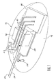
- the reference 10 designates generally a mobile case of a peripheral according to the invention, intended for use on a computer.
- the housing 10 is shown as if it was transparent, so that the elements it contains are visible in the figure.
- This housing 10 has an external shape allowing a user to grab it, move it and direct it at will in a workspace or area three-dimensional.
- the outer surface of the case 10 may have fingerprints (not shown) designed to receive the fingers of the user.
- the mobile unit 10 of the peripheral according to the invention also present on its outer surface a lower face 12, of substantially flat general configuration.
- This face 12 allows the user to place the housing 10 on a planar support, generally horizontal, such as that that has been schematically illustrated at 14 in FIG. 3. More specifically, the housing 10 can be moved and oriented at will on the support 14, in the manner of a classic 2D computer mouse, when its face 12 is placed on this support.
- the input device further includes means for detecting the position and the three-dimensional orientation of the housing 10 to inside the workspace in which this housing can be moved and oriented by the user.
- these means for detecting the position and the three-dimensional orientation of the housing 10 include an electromagnetic sensor 16, mounted at inside this case.
- a stationary source 17 (figure 3), placed on the table supporting the screen computer display or any other fixed installation location, creates a field low frequency 3D magnetic in the work area.
- the electromagnetic sensor 16 is sensitive to changes in this 3D magnetic field caused by his own travels.
- the stationary source 17 is located at the origin of a fixed orthonormal reference frame R (O, i, j, k), in which the electromagnetic sensor 16 measures the variations of x, y, z coordinates and orientations ⁇ , ⁇ , ⁇ of the housing 10 inside the space of work where the latter can be moved by the user.
- R orthonormal reference frame
- the electromagnetic sensor 16, too called “3D tracker”, can in particular be of the type “Fastrak” manufactured by the company “Polhemus” or of the type “Flock of Birds” manufactured by the company “Ascension”. It is generally associated with an electronic circuit pretreatment 18 ( Figure 2). More specifically, the electronic pretreatment circuit 18 is placed in a stationary box located outside the box mobile 10, and it is electrically connected to the sensor electromagnetic 16 by an electrical conductor 20 forming a first serial link between the housing 10 and the rest of the installation.
- the set including the sensor 16, the stationary source 17 and the electronic pretreatment circuit 18 is well known skilled in the art, so that no description detailed will not be made. Such an assembly is described, for example, in US-A-5,237,647.
- the means position and orientation detection three-dimensional housing 10 can be realized differently, for example based on ultrasonic or light systems, or by means accelerometers or gyroscopes.
- a contactor 22 two-state, controlling a switch is placed on the underside 12 of the housing 10. More precisely, the mounting of the contactor 22 on the face 12 is made in such a way that the contactor changes automatically state when the housing 10 is installed on the flat support 14 and when it is lifted from this support. Thus, the contactor 22 occupies for example a closed state when the case is placed on its support 14 and an open state when raised from it support.
- the closed state of contactor 22 constitutes for this a first state, corresponding to a mode two-dimensional operation of the device.
- the open state of contactor 22 constitutes a second state corresponding to an operating mode three-dimensional device.
- contactor 22 on face 12 of the housing 10 therefore allows to pass automatically the input device according to the invention from a 2D operating mode to a 3D operation, and vice versa, depending on whether it is installed or not on the support 14.
- buttons 24 of triggering of computer processing commanding switches are intended for perform functions comparable to those of buttons that usually equip 2D design mice classic. These are therefore well known elements of skilled in the art, so that no description detailed will not be made.
- An electronic circuit 26 for shaping is also placed inside the housing 10 of the peripheral.
- This electronic circuit 26 is connected electrically to the switch of contactor 22 and to switches associated with buttons 24, respectively by electrical conductors 28 and 30. It has for functions to eliminate rebounds related to change status of button switches and contactor and perform state coding of these switches.
- This electronic circuit 26 is similar in its function to the electronic setting circuit shape that equips existing 2D mice, so no detailed description will be given.
- the coded signals coming from the electronic circuit 26 are transmitted to the central processing unit 32 from the computer, driving the screen 34 ( Figure 3) of the display device, by an electrical conductor 36.
- This electrical conductor 36 forms a second serial link between the mobile unit 10 of the input device and central unit 32 of the computer.
- drivers 20 and 36 from box 10 are grouped together in the form of a cable 38 ( Figure 3) connecting this housing to the rest of the installation.
- the electronic circuit 18 for pretreatment is connected to a first serial port 37 of the unit central computer 32 by a first link series materialized by an electrical conductor 38.
- the electrical conductor 36 materializing the second serial link is connected on a second serial port 39 of the central processing unit 32 of the computer.
- the signals admitted by the first port series 37 are processed by a first software module 40 allowing to recover the coordinates x, y and z and the ⁇ , ⁇ and ⁇ orientations of the electromagnetic sensor 16.
- the data accepted by the second serial port 39 of CPU 32 are processed in a second software module 42, allowing to recover the state and the transitions status of switches of contactor 22 and input device buttons 24 conforming to the invention.
- the first software module 40 is a module software conventionally associated with the set constituted by the electromagnetic sensor 16, the source stationary 17 magnetic field and circuit electronic 18 pre-treatment in facilities using a tracker. It is therefore well known to skilled in the art, so that no description detailed will not be made.
- the second software module 42 is similar to the software module usually associated with 2D mouse buttons of classic design. It is therefore also well known to those skilled in the art, so it will not be described either detailed.
- the data from the first software module 40 and the second software module 42 are operated, inside the central processing unit 32 of the computer, by a third software module 44.
- This third software module 44 takes into account the changes in state of contactor 22 and calculates the coordinates and orientations of a 2D 45 cursor or a 3D cursor 46 ( Figure 3), depending on whether the input device is in operating mode two-dimensional or in operating mode three-dimensional.
- the third software module 44 acts automatically in one mode two-dimensional operation of the device, then that it acts according to a mode of operation three-dimensional device when the housing 10 is lifted from its support 14, that is to say when the contactor 22 occupies its second state.
- the third module software 44 transforms the x, y and z coordinates and the ⁇ , ⁇ and ⁇ orientations of the housing 10 in the coordinate system fixed orthonormal R (O, i, j, k) linked to support 14 in two x ", y" coordinates and y "orientation of the 2D cursor 45 in an orthonormal coordinate system R "(O", i ", j", k ") linked to screen 34.
- the third module software 44 transforms the x, y, z coordinates and the orientations ⁇ , ⁇ , ⁇ of the housing 10 in the frame orthonormal fixed R (O, i, j, k) in coordinates x ', y', z 'and orientations ⁇ ', ⁇ ', ⁇ ' of the 3D cursor 46 in an orthonormal coordinate system R '(O', i ', j', k ') linked to a virtual space corresponding to a scene displayed on screen 34.
- displacement and change orientation of the housing 10 in the working area translate into displacement and change corresponding orientation of the 3D cursor 46 in the virtual scene displayed on the screen 34.
- x 1 and y 1 represent the coordinates and ⁇ 1 the orientation of the housing 10 in the frame R, in an initial position P1 of the housing 10 corresponding to the instant when it is placed on the support 14 and triggers the input device to enter 2D operating mode.
- x " 1 and Y” 1 represent the coordinates and ⁇ 1 the orientation of the 2D cursor 45 in the frame R ", in an initial position P" 1 of this cursor corresponding to the position P1 of the housing 10.
- This initial position P "1 of the 2D cursor 45 is also the final position of this cursor, during the previous passage of the peripheral from the 2D operating mode to the 3D operating mode.
- x 2 and y 2 represent the coordinates and ⁇ 2 the orientation of the housing 10 in the frame R, at the instant considered, in a position P2 of the housing on the support.
- x " 2 and y” 2 represent the coordinates and ⁇ " 2 the orientation of the 2D cursor 45 in the frame R", at the same time, in a position P "2 of this cursor corresponding to the position P2 of the housing 10 .
- Fx, Fy and F ⁇ designate the configurable gains, respectively in x, y and ⁇ , in this 2D operating mode.
- x 1 , y 1 , z 1 and ⁇ 1 , ⁇ 1 , ⁇ 1 respectively represent the coordinates and the orientations of the housing 10 in the frame R, in an initial position P1 of this housing.
- x 2 , y 2 , z 2 and ⁇ 2 , ⁇ 2 , ⁇ 2 respectively represent the coordinates and the orientations of the housing 10 in the frame R, in a position P2 of this housing corresponding to the instant considered.
- x ' 1 , y' 1 , z ' 1 and ⁇ ' 1 , ⁇ ' 1 , ⁇ ' 1 respectively represent the coordinates and the orientations of the 3D cursor 46 in the frame R ', in a position P'1 corresponding to the position P1 of the housing.
- x ' 2 , y' 2 , z ' 2 and ⁇ ' 2 , ⁇ ' 2 , Y'2 respectively represent the coordinates and the orientations of the 3D cursor in the frame R', in a position P'2 corresponding to the position P2 of the housing.
- Cx, Cy, Cz, C ⁇ , C ⁇ and C ⁇ represent the configurable gains, respectively in x, y, z, ⁇ , ⁇ , ⁇ , in the 3D operating mode.
- the input device according to the invention constitutes an original device, which allows to switch automatically from an operation two-dimensional to three-dimensional operation, and conversely, without the need to resort to several separate devices. This constitutes a valuable benefit to users called upon to work alternately in a virtual space three-dimensional and in a two-dimensional plane. From this point of view, it should be noted that the mode of two-dimensional operation can also allow move the cursor in a plane different from the screen, by performing a additional transformation of the corresponding data projection of coordinates and orientation in this other shot.
- the mobile device box input can also contain the usual items of a 2D mouse of classical design, in addition to the contactor 22 and means 16 for detecting the three-dimensional position and orientation of the housing.
- the third software module 44 can be replaced by a module operating from the described when the device is in its three-dimensional and working mode of operation in the same way as software associated with classic 2D mice, when the device is in its two-dimensional mode of operation. He is at note, however, that in this case the size of the box 10 is slightly increased and that none cursor 46 cannot be changed controlled in two-dimensional operating mode.
Landscapes
- Engineering & Computer Science (AREA)
- General Engineering & Computer Science (AREA)
- Theoretical Computer Science (AREA)
- Human Computer Interaction (AREA)
- Physics & Mathematics (AREA)
- General Physics & Mathematics (AREA)
- Position Input By Displaying (AREA)
Abstract
Description
- détermination du mode de fonctionnement du périphérique ;
- calcul des coordonnées x', y', z' et orientations α', β', γ' d'un curseur 3D affiché sur l'écran (34), dans un repère orthonormé R' (O',i',j',k') lié à une scène virtuelle représentée sur l'écran, à partir des signaux délivrés par les moyens (16) de détection de position et d'orientation tridimensionnelles, dans le mode de fonctionnement tridimensionnel ;
- calcul des coordonnées x", y" et orientation γ" d'un curseur 2D, dans un repère orthonormé R" (O", i", j", k") lié à l'écran et dont les axes i" et j" sont situés dans le plan de l'écran, à partir des signaux délivrés par les moyens de détection de position et d'orientation tridimensionnelles, dans le mode de fonctionnement bidimensionnel.
- la figure 1 est une vue en perspective représentant schématiquement le boítier d'un périphérique d'entrée conforme à l'invention et les éléments qu'il contient ;
- la figure 2 représente schématiquement un exemple de réalisation du périphérique d'entrée conforme à l'invention, incluant le boítier de la figure 1, ainsi que les éléments extérieurs à ce boítier assurant notamment sa liaison avec l'unité centrale de l'ordinateur associé ; et
- la figure 3 est une perspective très schématique destinée à expliquer les changements de coordonnées effectués dans l'unité centrale, à partir des signaux délivrés par le périphérique d'entrée, pour permettre la représentation de la position et de l'orientation du boítier du périphérique d'entrée par un curseur 2D ou par un curseur 3D, sur l'écran d'affichage de l'ordinateur.
Claims (4)
- Périphérique d'entrée pour ordinateur, comprenant un boítier mobile (10) apte à être saisi par un utilisateur, et des moyens (16,18) de détection de position et d'orientation tridimensionnelles du boítier, caractérisé par le fait qu'un contacteur (22) à deux états est placé sur une face (12)du boítier (10) apte à être posée sur un support plan (14), de façon à occuper un premier état correspondant à un mode de fonctionnement bidimensionnel du périphérique, lorsque le boítier est posé sur le support, et un deuxième état, correspondant à un mode de fonctionnement tridimensionnel du périphérique, lorsque le boítier est soulevé du support.
- Périphérique selon la revendication 1, dans lequel les moyens de détection de position et d'orientation tridimensionnelles du boítier comprennent un capteur électromagnétique (16) monté dans le boítier (10).
- Périphérique selon la revendication 2, dans lequel les moyens de détection de position et d'orientation tridimensionnelles du boítier comprennent de plus un circuit électronique (18) de prétraitement, extérieur au boítier (10), relié au capteur électromagnétique (16) par un conducteur électrique (20).
- Périphérique selon l'une quelconque des revendications précédentes, dans lequel le boítier (10) est muni d'au moins un bouton (24) de déclenchement de traitements informatiques.
Applications Claiming Priority (2)
| Application Number | Priority Date | Filing Date | Title |
|---|---|---|---|
| FR9711646A FR2768528B1 (fr) | 1997-09-18 | 1997-09-18 | Peripherique d'entree pour ordinateur, a commutation automatique entre des modes de fonctionnement 3d et 2d, et son procede d'interaction avec un ecran d'affichage |
| FR9711646 | 1997-09-18 |
Publications (2)
| Publication Number | Publication Date |
|---|---|
| EP0903684A1 true EP0903684A1 (fr) | 1999-03-24 |
| EP0903684B1 EP0903684B1 (fr) | 2003-12-17 |
Family
ID=9511232
Family Applications (1)
| Application Number | Title | Priority Date | Filing Date |
|---|---|---|---|
| EP98402281A Expired - Lifetime EP0903684B1 (fr) | 1997-09-18 | 1998-09-16 | Périphérique d'entrée pour ordinateur, à commutation automatique entre des modes de fonctionnement 3D et 2D, et son procédé d'interaction avec écran d'affichage |
Country Status (7)
| Country | Link |
|---|---|
| US (1) | US6342878B1 (fr) |
| EP (1) | EP0903684B1 (fr) |
| AU (1) | AU9170098A (fr) |
| DE (1) | DE69820554T2 (fr) |
| ES (1) | ES2212237T3 (fr) |
| FR (1) | FR2768528B1 (fr) |
| WO (1) | WO1999014709A1 (fr) |
Cited By (1)
| Publication number | Priority date | Publication date | Assignee | Title |
|---|---|---|---|---|
| WO2003050753A3 (fr) * | 2001-12-11 | 2004-01-22 | Koninkl Philips Electronics Nv | Souris d'ordinateur a double fonctionnalite |
Families Citing this family (23)
| Publication number | Priority date | Publication date | Assignee | Title |
|---|---|---|---|---|
| US6710765B1 (en) | 1999-10-05 | 2004-03-23 | Nippon Telegraph And Telephone Corporation | Input device of 3-D translation and rotation and its method and recording medium |
| US7061468B2 (en) * | 2001-04-10 | 2006-06-13 | Logitech Europe S.A. | Hybrid presentation controller and computer input device |
| JP3762309B2 (ja) * | 2002-02-18 | 2006-04-05 | キヤノン株式会社 | 位置方向測定装置および情報処理方法 |
| FR2847994B1 (fr) * | 2002-11-28 | 2005-06-10 | Ge Med Sys Global Tech Co Llc | Peripherique pour la manipulation d'images 3d, ensemble comportant un tel peripherique et installation pour la visualisation d'images medicales en salle d'intervention et/ou d'examen |
| AU2002952977A0 (en) * | 2002-11-28 | 2002-12-12 | Hi-Fi Design Pty Ltd | Computer mouse with magnetic orientation features |
| JP2004199496A (ja) * | 2002-12-19 | 2004-07-15 | Sony Corp | 情報処理装置および方法、並びにプログラム |
| US7209116B2 (en) | 2003-10-08 | 2007-04-24 | Universal Electronics Inc. | Control device having integrated mouse and remote control capabilities |
| WO2005119356A2 (fr) | 2004-05-28 | 2005-12-15 | Erik Jan Banning | Systeme interactif de pointage direct et de controle de presentation facile a deployer et procede d'etalonnage correspondant |
| US7821494B2 (en) * | 2005-05-13 | 2010-10-26 | Industrial Technology Research Institute | Inertial mouse |
| KR100739980B1 (ko) * | 2005-05-13 | 2007-07-16 | 인더스트리얼 테크놀로지 리서치 인스티튜트 | 관성 감지 입력장치 |
| US9285897B2 (en) | 2005-07-13 | 2016-03-15 | Ultimate Pointer, L.L.C. | Easily deployable interactive direct-pointing system and calibration method therefor |
| TWI300473B (en) * | 2005-12-14 | 2008-09-01 | Ind Tech Res Inst | A status sensing mechanism and the cursor-control device applying the same |
| TWI319539B (en) * | 2006-11-29 | 2010-01-11 | Ind Tech Res Inst | Pointing device |
| US11228753B1 (en) | 2006-12-28 | 2022-01-18 | Robert Edwin Douglas | Method and apparatus for performing stereoscopic zooming on a head display unit |
| US11315307B1 (en) | 2006-12-28 | 2022-04-26 | Tipping Point Medical Images, Llc | Method and apparatus for performing rotating viewpoints using a head display unit |
| US10795457B2 (en) | 2006-12-28 | 2020-10-06 | D3D Technologies, Inc. | Interactive 3D cursor |
| US11275242B1 (en) | 2006-12-28 | 2022-03-15 | Tipping Point Medical Images, Llc | Method and apparatus for performing stereoscopic rotation of a volume on a head display unit |
| TWI334559B (en) * | 2007-08-28 | 2010-12-11 | Ind Tech Res Inst | Interactive pointing device |
| WO2010108499A2 (fr) * | 2009-03-22 | 2010-09-30 | Algreatly Cherif Atia | Procédé et système de navigation 3d |
| US8552980B2 (en) * | 2009-04-30 | 2013-10-08 | Gregory A. Shaver | Computer input devices and associated computing devices, software, and methods |
| US9829996B2 (en) * | 2012-06-25 | 2017-11-28 | Zspace, Inc. | Operations in a three dimensional display system |
| EP2801891B1 (fr) * | 2013-05-09 | 2018-12-26 | Samsung Electronics Co., Ltd | Appareil d'entrée, dispositif de pointage, procédé d'affichage de pointeur et support enregistrable |
| US10890982B2 (en) * | 2018-12-18 | 2021-01-12 | Samsung Electronics Co., Ltd. | System and method for multipurpose input device for two-dimensional and three-dimensional environments |
Citations (3)
| Publication number | Priority date | Publication date | Assignee | Title |
|---|---|---|---|---|
| EP0420500A2 (fr) * | 1989-09-26 | 1991-04-03 | Cyber Scientific Incorporated | Système acoustique digital |
| US5144594A (en) * | 1991-05-29 | 1992-09-01 | Cyber Scientific | Acoustic mouse system |
| US5237647A (en) * | 1989-09-15 | 1993-08-17 | Massachusetts Institute Of Technology | Computer aided drawing in three dimensions |
Family Cites Families (2)
| Publication number | Priority date | Publication date | Assignee | Title |
|---|---|---|---|---|
| US5019809A (en) * | 1988-07-29 | 1991-05-28 | University Of Toronto Innovations Foundation | Two-dimensional emulation of three-dimensional trackball |
| WO1993011526A1 (fr) * | 1991-12-03 | 1993-06-10 | Logitech, Inc. | Souris tridimensionnelle montee sur un support |
-
1997
- 1997-09-18 FR FR9711646A patent/FR2768528B1/fr not_active Expired - Fee Related
-
1998
- 1998-09-01 US US09/145,420 patent/US6342878B1/en not_active Expired - Fee Related
- 1998-09-16 ES ES98402281T patent/ES2212237T3/es not_active Expired - Lifetime
- 1998-09-16 DE DE69820554T patent/DE69820554T2/de not_active Expired - Lifetime
- 1998-09-16 EP EP98402281A patent/EP0903684B1/fr not_active Expired - Lifetime
- 1998-09-17 WO PCT/FR1998/001996 patent/WO1999014709A1/fr not_active Ceased
- 1998-09-17 AU AU91700/98A patent/AU9170098A/en not_active Abandoned
Patent Citations (3)
| Publication number | Priority date | Publication date | Assignee | Title |
|---|---|---|---|---|
| US5237647A (en) * | 1989-09-15 | 1993-08-17 | Massachusetts Institute Of Technology | Computer aided drawing in three dimensions |
| EP0420500A2 (fr) * | 1989-09-26 | 1991-04-03 | Cyber Scientific Incorporated | Système acoustique digital |
| US5144594A (en) * | 1991-05-29 | 1992-09-01 | Cyber Scientific | Acoustic mouse system |
Non-Patent Citations (1)
| Title |
|---|
| "THREE-DIMENSIONAL POINTING DEVICE", IBM TECHNICAL DISCLOSURE BULLETIN, vol. 37, no. 6A, 1 June 1994 (1994-06-01), pages 597, XP000455898 * |
Cited By (1)
| Publication number | Priority date | Publication date | Assignee | Title |
|---|---|---|---|---|
| WO2003050753A3 (fr) * | 2001-12-11 | 2004-01-22 | Koninkl Philips Electronics Nv | Souris d'ordinateur a double fonctionnalite |
Also Published As
| Publication number | Publication date |
|---|---|
| US6342878B1 (en) | 2002-01-29 |
| DE69820554D1 (de) | 2004-01-29 |
| FR2768528A1 (fr) | 1999-03-19 |
| DE69820554T2 (de) | 2004-09-23 |
| EP0903684B1 (fr) | 2003-12-17 |
| ES2212237T3 (es) | 2004-07-16 |
| FR2768528B1 (fr) | 2001-01-12 |
| WO1999014709A1 (fr) | 1999-03-25 |
| AU9170098A (en) | 1999-04-05 |
Similar Documents
| Publication | Publication Date | Title |
|---|---|---|
| EP0903684B1 (fr) | Périphérique d'entrée pour ordinateur, à commutation automatique entre des modes de fonctionnement 3D et 2D, et son procédé d'interaction avec écran d'affichage | |
| JP3785902B2 (ja) | デバイス、デバイスの制御方法、ポインタの移動方法 | |
| US7358963B2 (en) | Mouse having an optically-based scrolling feature | |
| US7102626B2 (en) | Multi-function pointing device | |
| US9703398B2 (en) | Pointing device using proximity sensing | |
| US20200409532A1 (en) | Input device for vr/ar applications | |
| US5900863A (en) | Method and apparatus for controlling computer without touching input device | |
| US7382352B2 (en) | Optical joystick for hand-held communication device | |
| US7366540B2 (en) | Hand-held communication device as pointing device | |
| US20030226968A1 (en) | Apparatus and method for inputting data | |
| US10558279B2 (en) | Dual mode optical navigation device | |
| US20060164382A1 (en) | Image manipulation in response to a movement of a display | |
| US10268277B2 (en) | Gesture based manipulation of three-dimensional images | |
| FR2686440A1 (fr) | Dispositif de gestion multimode d'un curseur sur l'ecran d'un dispositif d'affichage. | |
| KR102799611B1 (ko) | 이동 단말기 | |
| KR100936046B1 (ko) | 촉각 센서를 이용한 마우스 기능을 갖는 터치패드 구현방법 | |
| WO2003003185A1 (fr) | Systeme permettant la mise en oeuvre d'une interface utilisateur | |
| KR100749033B1 (ko) | 두 눈에서 반사되는 빛을 추적하여 단말기를 조작하는방법, 및 그 장치 | |
| Matulic et al. | Above-Screen Fingertip Tracking with a Phone in Virtual Reality | |
| EP1424710B1 (fr) | Dispositif de commande d'au moins deux fonctions d'un organe et/ ou d'au moins deux parties distinctes d'un organe | |
| US20060284831A1 (en) | Optical input device with a rotatable surface | |
| KR100473843B1 (ko) | 정보선택장치및방법,휴대정보단말기용정보선택장치및방법 | |
| KR100648964B1 (ko) | 격자 또는 인식 가능한 패턴 이동의 감지를 이용한 2차원포인팅 장치 | |
| CN1985237A (zh) | 集成无线指示装置、具有该装置的终端设备及使用该无线指示装置的指示方法 | |
| US11500103B2 (en) | Mobile terminal |
Legal Events
| Date | Code | Title | Description |
|---|---|---|---|
| PUAI | Public reference made under article 153(3) epc to a published international application that has entered the european phase |
Free format text: ORIGINAL CODE: 0009012 |
|
| AK | Designated contracting states |
Kind code of ref document: A1 Designated state(s): CH DE ES GB IT LI NL SE |
|
| AX | Request for extension of the european patent |
Free format text: AL;LT;LV;MK;RO;SI |
|
| 17P | Request for examination filed |
Effective date: 19990908 |
|
| AKX | Designation fees paid |
Free format text: CH DE ES GB IT LI NL SE |
|
| GRAH | Despatch of communication of intention to grant a patent |
Free format text: ORIGINAL CODE: EPIDOS IGRA |
|
| GRAH | Despatch of communication of intention to grant a patent |
Free format text: ORIGINAL CODE: EPIDOS IGRA |
|
| GRAA | (expected) grant |
Free format text: ORIGINAL CODE: 0009210 |
|
| AK | Designated contracting states |
Kind code of ref document: B1 Designated state(s): CH DE ES GB IT LI NL SE |
|
| REG | Reference to a national code |
Ref country code: GB Ref legal event code: FG4D Free format text: NOT ENGLISH |
|
| REG | Reference to a national code |
Ref country code: CH Ref legal event code: EP |
|
| REF | Corresponds to: |
Ref document number: 69820554 Country of ref document: DE Date of ref document: 20040129 Kind code of ref document: P |
|
| REG | Reference to a national code |
Ref country code: SE Ref legal event code: TRGR |
|
| GBT | Gb: translation of ep patent filed (gb section 77(6)(a)/1977) |
Effective date: 20040303 |
|
| REG | Reference to a national code |
Ref country code: ES Ref legal event code: FG2A Ref document number: 2212237 Country of ref document: ES Kind code of ref document: T3 |
|
| PLBE | No opposition filed within time limit |
Free format text: ORIGINAL CODE: 0009261 |
|
| STAA | Information on the status of an ep patent application or granted ep patent |
Free format text: STATUS: NO OPPOSITION FILED WITHIN TIME LIMIT |
|
| 26N | No opposition filed |
Effective date: 20040920 |
|
| PGFP | Annual fee paid to national office [announced via postgrant information from national office to epo] |
Ref country code: ES Payment date: 20090924 Year of fee payment: 12 |
|
| PGFP | Annual fee paid to national office [announced via postgrant information from national office to epo] |
Ref country code: SE Payment date: 20090915 Year of fee payment: 12 Ref country code: NL Payment date: 20090915 Year of fee payment: 12 Ref country code: GB Payment date: 20090922 Year of fee payment: 12 Ref country code: CH Payment date: 20090923 Year of fee payment: 12 |
|
| PGFP | Annual fee paid to national office [announced via postgrant information from national office to epo] |
Ref country code: DE Payment date: 20090922 Year of fee payment: 12 |
|
| PGFP | Annual fee paid to national office [announced via postgrant information from national office to epo] |
Ref country code: IT Payment date: 20090925 Year of fee payment: 12 |
|
| REG | Reference to a national code |
Ref country code: NL Ref legal event code: V1 Effective date: 20110401 |
|
| REG | Reference to a national code |
Ref country code: CH Ref legal event code: PL |
|
| REG | Reference to a national code |
Ref country code: SE Ref legal event code: EUG |
|
| GBPC | Gb: european patent ceased through non-payment of renewal fee |
Effective date: 20100916 |
|
| PG25 | Lapsed in a contracting state [announced via postgrant information from national office to epo] |
Ref country code: IT Free format text: LAPSE BECAUSE OF NON-PAYMENT OF DUE FEES Effective date: 20100916 |
|
| REG | Reference to a national code |
Ref country code: DE Ref legal event code: R119 Ref document number: 69820554 Country of ref document: DE Effective date: 20110401 |
|
| PG25 | Lapsed in a contracting state [announced via postgrant information from national office to epo] |
Ref country code: LI Free format text: LAPSE BECAUSE OF NON-PAYMENT OF DUE FEES Effective date: 20100930 Ref country code: DE Free format text: LAPSE BECAUSE OF NON-PAYMENT OF DUE FEES Effective date: 20110401 Ref country code: CH Free format text: LAPSE BECAUSE OF NON-PAYMENT OF DUE FEES Effective date: 20100930 |
|
| PG25 | Lapsed in a contracting state [announced via postgrant information from national office to epo] |
Ref country code: GB Free format text: LAPSE BECAUSE OF NON-PAYMENT OF DUE FEES Effective date: 20100916 Ref country code: NL Free format text: LAPSE BECAUSE OF NON-PAYMENT OF DUE FEES Effective date: 20110401 |
|
| REG | Reference to a national code |
Ref country code: ES Ref legal event code: FD2A Effective date: 20111019 |
|
| PG25 | Lapsed in a contracting state [announced via postgrant information from national office to epo] |
Ref country code: ES Free format text: LAPSE BECAUSE OF NON-PAYMENT OF DUE FEES Effective date: 20100917 |
|
| PG25 | Lapsed in a contracting state [announced via postgrant information from national office to epo] |
Ref country code: SE Free format text: LAPSE BECAUSE OF NON-PAYMENT OF DUE FEES Effective date: 20100917 |