EP0903671B1 - A sound warning circuit for a PCI hot plug - Google Patents
A sound warning circuit for a PCI hot plug Download PDFInfo
- Publication number
- EP0903671B1 EP0903671B1 EP98306109A EP98306109A EP0903671B1 EP 0903671 B1 EP0903671 B1 EP 0903671B1 EP 98306109 A EP98306109 A EP 98306109A EP 98306109 A EP98306109 A EP 98306109A EP 0903671 B1 EP0903671 B1 EP 0903671B1
- Authority
- EP
- European Patent Office
- Prior art keywords
- input
- bit
- warning circuit
- output
- sound warning
- Prior art date
- Legal status (The legal status is an assumption and is not a legal conclusion. Google has not performed a legal analysis and makes no representation as to the accuracy of the status listed.)
- Expired - Lifetime
Links
Images


Classifications
-
- G—PHYSICS
- G06—COMPUTING OR CALCULATING; COUNTING
- G06F—ELECTRIC DIGITAL DATA PROCESSING
- G06F1/00—Details not covered by groups G06F3/00 - G06F13/00 and G06F21/00
-
- G—PHYSICS
- G06—COMPUTING OR CALCULATING; COUNTING
- G06F—ELECTRIC DIGITAL DATA PROCESSING
- G06F13/00—Interconnection of, or transfer of information or other signals between, memories, input/output devices or central processing units
- G06F13/38—Information transfer, e.g. on bus
- G06F13/40—Bus structure
- G06F13/4063—Device-to-bus coupling
- G06F13/4068—Electrical coupling
- G06F13/4081—Live connection to bus, e.g. hot-plugging
Definitions
- This invention relates to a sound warning circuit for a Peripheral Components Interconnects (PCI) hot plug.
- PCI Peripheral Components Interconnects
- the speaker warns the user when the user mistakenly accesses another adapter card while executing the PCI hot plug.
- the PCI hot plug system manages the adapter card in the PCI slot that controls the computer's auxiliary equipment. Researched by numerous companies, the PCI system can renew the adapter card to a new version while the system is operating and, when damage to the adapter card is discovered, can change to a new adapter card.
- the user gives a command to use the computer's system port B. After the system creates the environment for PCI hot plug, it exchanges the adapter card.
- EP-A-0637793 discloses a docking station for a portable computer which is arranged to allow hot docking. Either or both of the docking station and the portable computer are provided with sensing mechanisms which detect the approach of the portable computer to the docking station and cause the device(s) to enter suspension routines which, for example, close programs and data files, power down connector pins etc.
- WO-A-90/15551 discloses a card holder for a chip card which issues an audible warning to remind the user to enter a transaction into the card via a keypad mounted on the holder.
- An aim of the invention is to provide a sound warning circuit for a PCI hot plug.
- the invention has been devised to solve the above problems. If the PCI hot plug accesses an unprepared adapter card, the speaker sounds a warning to the user to prevent further PCI hot plug execution.
- a sound warning circuit for a PCI hot plug as defined in claim 1.
- the sound warning circuit may comprise a timer adapted to enable the first input signal as an oscillating signal when the said first bit of the system port is at the said first logic level.
- the audible warning is generated by a speaker receiving as its drive signal the output of a speaker driver responsive to the said output signal.
- the first input signal may be enabled when the said first bit of the system port is at the said first logic level.
- the audible warning is generated by a buzzer receiving as its drive signal the said output signal.
- the said first input signal may be disabled when the said first bit of the system port is not at the said first logic level.
- the said second input signal may be disabled when the said second bit of the system port is not at the said second logic level.
- the chassis ground cable may be connected to the PCI card VDD input and to a fixed screw comprising a ground metal plate reserved pin used to fix the PCI card to the system.
- the fixed screw is always LOW if the screw is connected to the PCI card VDD input, and if power to the PCI card is off, the screw is LOW if power is on and the screw is connected to the ground metal plate and the screw is HIGH if the screw is separated from the ground metal plate.
- the chassis ground cable may be connected to the fixed screw by going through the input/output board and the PCI card or via the input/output board.
- the said second input signal may be derived from the result of Oring the said second bit of the system port with one or more chassis ground cable inputs.
- the sound warning circuit may further comprise:
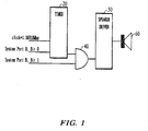
- Figure 1 is a preferred embodiment of a sound warning circuit for a PCI hot plug based on the present invention.
- the sound warning circuit comprises a timer 20 which receives as inputs a clock signal and the system port B's bit 0 input.
- the output of timer 20 is connected to an input of AND gate 40, the other input of which receives the system port B's bit 1.
- the output of AND gate 40 is provided as an input to speaker driver 50, the output of which drives the speaker 60.
- the timer 20 starts dividing the clock by user programmed number n, resulting in a signal with 1.19318/n MHz frequency. Furthermore, when the system port B's bit 1 (input/output address is 0061h) is set to '1' by the user's command, the 1.19318/n MHz signal goes through the logic AND gate 40 to the speaker driver 50 where it is amplified and is played through the speaker 60.
- the produced sound can be changed to a high or low frequency sound, depending on its use, by the user changing the timer's n.
- the sound warning circuit for the PCI hot plug constructed as described above, can interface with the system using a PCI card, as now described.
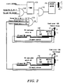
- FIGS 2 and 3 are diagrams of a first embodiment of the sound warning circuit as connected to a system using a PCI card
- Figures 4 and 5 are diagrams of a second embodiment of the sound warning circuit as connected to system using a PCI card.
- a screw 10 fixes a wire 12, 13 to a grounded metal plate 11.
- the grounded metal plate 11 is used to secure the PCI card 160, 170, 260, 270 to the wire 12, 13 which is "pulled up" to logic level '1' and receives VDD from the input/output board through a 10 kW resistance 14.
- wire 12, 13, set to level T is connected to screw 10 of the metal plate 11, which secures said PCI card, its logic level becomes '0' due to the chassis ground.
- the sound warning circuit includes a timer 120 having as inputs a clock input and the output of a logic OR gate 110.
- the logic OR gate 110 receives as inputs the system port B's bit 0 and a PCI card VDD input.
- the output of timer 120 is provided as one input to logic AND gate 140, the other input of which is connected to the output of logic OR gate 130.
- Logic OR gate 130 receives as inputs the system port B's bit 1 input, a chassis ground cable 0 input from the I/O board associated with PCI card 170, and a chassis ground cable 1 input from the I/O board associated with PCI card 160.
- Logic AND gate 140 provides its output to speaker driver 150, and driver 150 drives audio output device 180.
- the chassis ground cable 0 is connected to the input/output board-speaker circuit, and connects through the PCI card 170, to a fixed screw comprising PCI card 170's reserved pin.
- the chassis ground cable 1 connects, through the PCI card 160, to the fixed screw which serves as the reserved pin of PCI card 160.
- the chassis ground cable 1 connected to the PCI card 160's fixed screw receives VDD from the input/output board because the PCI card's power is on, and its level drops to '0' because said fixed screw is connected to the metal plate, as grounded to secure the PCI card 160.
- the chassis ground cable 0, connected to the unfixable PCI card 170's fixed screw cannot receive the VDD from the input/output board when the power is off, its level remains '0', even if the fixed screw is disconnected from the metal plate. Therefore, unless the user sets the system port B's bit 1 to 0' to test the speaker's performance, the speaker driver 150 does not operate, and consequently the speaker does not operate.
- the "power on” PCI card 160 does not run the speaker 180 because the screw is connected to the metal plate; the "power off” PCI card 170 cannot run the speaker 180 because the screw cannot receive the VDD from the input/output board.
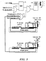
- FIG 3 shows the operation of the sound warning circuit, connected to a system using a card when the user makes a mistake.
- the cable level becomes '1' and it runs the speaker 180. If the user mistakenly separates the fixed screw from the metal plate when the PCI card's power is on, the speaker 180 warns the user that PCI hot plug is unprepared.
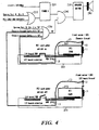
- Figures 4 and 5 show a further embodiment of the sound warning circuit, as connected directly to the system. That is, the fixed screws associated with the PCI card are connected directly to the respective chassis ground cables (as opposed to the previous two embodiments of Figures 2 and 3 , wherein the fixed screws associated with the PCI cards were connected through the respective PCI cards to the respective chassis ground cables).
- FIG 4 shows the operation of the sound warning circuit, connected directly to the system, when the user does not make a mistake.
- the chassis ground cable 1 connected to the input/output board-speaker circuit, connects directly, through the input/output board 265, to the fixed screw serving as PCI card 260's reserved pin.
- the chassis ground cable 1, connected to the secured PCI card 260's fixed screw receives VDD from the input/output board when the power is on, and its level drops to '0' because the fixed screw is connected to the metal plate, grounded to secure the PCI card 260.
- the "power on" PCI card 260 does not run the speaker 280 because the screw is connected to the metal plate; the "power off” PCI card 270 cannot run the speaker 280 because the screw cannot receive the VDD from the input/output board.
- FIG. 5 shows the operation of the sound warning circuit, connected directly to the system, when a user makes a mistake.
- the chassis ground cable 1 connected to fixed PCI card 260's fixed screw, receives VDD from the input/output board because PCI card 260's power is on, and its level drops to '0' because the fixed screw is connected to the metal plate, grounded to secure the PCI card 260.
- the cable level becomes '1' and it runs the speaker 280. If the user mistakenly separates the fixed screw from the metal plate when the PCI card's power is on, the speaker 280 warns the user that the PCI hot plug is unprepared.
- the user can reset the speaker using a reset switch, as now described.
- Figure 6 is a schematic diagram of a sound warning circuit, according to the invention, having a reset arrangement.
- the arrangement of Figure 6 is similar to the previous arrangements of Figures 2-5 . However, there are differences.
- the circuit of Figure 6 comprises: a logic AND gate 370 that takes as inputs the system reset # that is set to '0' during system reset or rerun, and the ground that goes through the reset switch 380; a D Flip-Flop 360 that takes as inputs VDD and said logic AND gate 370 output and makes the chassis ground cable the clock, the cable becoming '1' when each PCI card in the on state is separated from the system; a logic OR gate 310 that takes as inputs the system port B's bit 0 and said PCI card's VDD; a timer 320 that takes as an input a fixed frequency clock and divides it by said OR gate 310's output; a logic OR gate 330 that takes as inputs said D Flip-Flop 360's output and the system port B's bit 1; a logic AND gate 340 that takes as inputs said timer 320's output and said OR gate 330's output; a speaker driver 350 that takes as an input said AND gate 340 output; and a speaker 390 that runs
- logic OR gate 310 receives as inputs system port B's bit 0 and the PCI card VDD input.
- Timer 320 receives as inputs a clock input and the output of OR gate 310.
- the output of timer 320 is provided as an input to AND gate 340, the other input of which receives the output of OR gate 330.
- OR gate 330 receives as inputs system port B's bit 1, as well as the output of a D-type Flip-Flop 360.
- the D Flip-Flop 360 receives a chassis ground cable input, as well as a reset input from a reset arrangement including AND gate 370 and reset switch 380.
- the operation of the arrangement of Figure 6 is as follows.
- the speaker 390 operates when the timer 320's output is '1' and logic OR gate 330's output is '1'. Ignoring system port B, the logic OR gate 330 outputs a '1' when the chassis ground cable is set to a '1'. The chassis ground cable becomes a '1' when the user mistakenly separates the "power on" PCI card (described above in Figures 3 and 5 ). If the speaker 390 operates due to user mistake, the user turns on the reset switch 380. Then, because '0' is input to the logic AND gate 310, the D Flip-Flop 360 is cleared.
- the speaker 390 can be initialised by resetting the system, or by sending a system reset # signal '0' to AND gate 370 when the system power is on, or by making D Flip-Flop 360 use a '1' when the power is on.
- the sound warning circuit can use the speaker 390 to warn about the PCI hot plug.
- the fixed output frequency buzzer can also be used for warning.
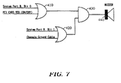
- FIG. 7 is a schematic diagram of a sound warning circuit according to the invention as used to drive a buzzer.
- a logic OR gate 410 receives the system port B's bit 0 and the PCI card VDD input.
- the output of OR gate 410 is provided as an input to AND gate 430, the other input of which receives the output of OR gate 420.
- OR gate 420 receives as inputs the system port B's bit 1 and the chassis ground cable input.
- the output of AND gate 430 is used to drive the buzzer 440. The operation of this arrangement will now be described.
- the chassis ground cable is in the power-on state through the PCI card or through the direct connection to the fixed screw of the PCI card, and the cable level becomes '1' when the fixed screw is separated.
- the logic OR gate 410 When the system port B's bit 0 becomes a 1' 1' or the PCI card VDD is on, the logic OR gate 410 outputs a '1'.
- system port B's bit 1 become a '1' or chassis ground cable becomes a '1'
- the logic OR gate 420 outputs a '1'.
- AND gate 430 outputs a '1', a condition which causes the buzzer 440 to sound.
- the buzzer 440 has a fixed output frequency and a driver within the buzzer, a clock input and timer are not required, and a warning can be produced with setup alone.
- a D Flip-Flop (such as Flip Flop 360 in Figure 6 ) can be used to reset the buzzer after its operation or during system operation.
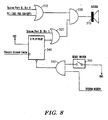
- FIG 8 is a schematic diagram of a sound warning circuit which employs both a buzzer and a reset arrangement similar to that shown in Figure 6 . That is to say, gates 510, 520 and 530, as well as buzzer 570, correspond to the gates 410, 420 and 430, as well as buzzer 440, shown in Figure 7 . However, the chassis ground cable input to gate 420 in Figure 7 is replaced, in Figure 8 , by the output of D Flip-Flop 540.
- the reset arrangement, including Flip-Flop 540, gate 550 and reset switch 560, as shown in Figure 8 is virtually identical to the reset arrangement, including Flip-Flop 360, gate 370 and reset switch 380, shown in Figure 6 .
- Figure 8 shows a sound warning circuit for the PCI hot plug comprising: a log AND gate 550 that takes as inputs the system reset that is set to '0' during system reset or rerun, and the ground that goes through the reset switch 560; a D Flip-Flop 540 that takes as inputs VDD and said AND gate 550 output and makes said chassis ground cable the clock, and the cable inputs become '1' when each PCI card in on state is separated from the system; a logic OR gate 510 that takes as inputs the system port B's bit 0 and PCI card's VDD; a logic OR gate 520 that takes as inputs the system port B's bit 1 and D Flip-Flop 540 output; a logic AND gate 530 that takes as inputs said OR gate 510 and OR gate 520 outputs; and a buzzer 570 that sounds when said AND gate 530 output is '1'. Operation of the arrangement of Figure 8 is as follows.
- the invention when operated as described above, prevents the entire system from going down because of an access to an unprepared PCI card by warning, through a speaker or buzzer, that the PCI card is in power-on state and is not to be separated.
Landscapes
- Engineering & Computer Science (AREA)
- Theoretical Computer Science (AREA)
- General Engineering & Computer Science (AREA)
- Physics & Mathematics (AREA)
- General Physics & Mathematics (AREA)
- Computer Hardware Design (AREA)
- Emergency Alarm Devices (AREA)
- Debugging And Monitoring (AREA)
- Electronic Switches (AREA)
Description
- This invention relates to a sound warning circuit for a Peripheral Components Interconnects (PCI) hot plug. In particular, in the circuit, the speaker warns the user when the user mistakenly accesses another adapter card while executing the PCI hot plug.
- The PCI hot plug system manages the adapter card in the PCI slot that controls the computer's auxiliary equipment. Researched by numerous companies, the PCI system can renew the adapter card to a new version while the system is operating and, when damage to the adapter card is discovered, can change to a new adapter card.
- The user gives a command to use the computer's system port B. After the system creates the environment for PCI hot plug, it exchanges the adapter card.
- Even when the entire system crashes because another, unprepared adapter card is accessed mistakenly by a user, a method to sense this has not been developed to the present day.
- In addition, a PCI hot plug is possible only when power to the input/output board and to the PCI card is off. Therefore, there is a need for the development of a method to determine whether the applicable card's power is off when the PCI hot plug is readied according to the system's command.
-
EP-A-0637793 discloses a docking station for a portable computer which is arranged to allow hot docking. Either or both of the docking station and the portable computer are provided with sensing mechanisms which detect the approach of the portable computer to the docking station and cause the device(s) to enter suspension routines which, for example, close programs and data files, power down connector pins etc.WO-A-90/15551 - An aim of the invention is to provide a sound warning circuit for a PCI hot plug. The invention has been devised to solve the above problems. If the PCI hot plug accesses an unprepared adapter card, the speaker sounds a warning to the user to prevent further PCI hot plug execution.
- According to a first aspect of the present invention there is provided a sound warning circuit for a PCI hot plug, as defined in
claim 1. - The sound warning circuit may comprise a timer adapted to enable the first input signal as an oscillating signal when the said first bit of the system port is at the said first logic level. Preferably in such a case, the audible warning is generated by a speaker receiving as its drive signal the output of a speaker driver responsive to the said output signal.
- Alternatively, the first input signal may be enabled when the said first bit of the system port is at the said first logic level. Preferably, in such a case, the audible warning is generated by a buzzer receiving as its drive signal the said output signal.
- The said first input signal may be disabled when the said first bit of the system port is not at the said first logic level.
- The said second input signal may be disabled when the said second bit of the system port is not at the said second logic level.
- The chassis ground cable may be connected to the PCI card VDD input and to a fixed screw comprising a ground metal plate reserved pin used to fix the PCI card to the system. Preferably, the fixed screw is always LOW if the screw is connected to the PCI card VDD input, and if power to the PCI card is off, the screw is LOW if power is on and the screw is connected to the ground metal plate and the screw is HIGH if the screw is separated from the ground metal plate.
- The chassis ground cable may be connected to the fixed screw by going through the input/output board and the PCI card or via the input/output board.
- The said second input signal may be derived from the result of Oring the said second bit of the system port with one or more chassis ground cable inputs.
- The sound warning circuit may further comprise:
- a logic AND gate for receiving a system reset #, set to LOW during system reset and rerun, and a reset switch input, and for producing an AND output;
- a reset switch connected at its input to ground and producing the said reset input at its output;
- a D Flip-Flop receiving the said AND output and a VDD input, the said D Flip-Flop receiving a clock input comprising a chassis ground cable input, the said chassis ground cable input being HIGH when each of a plurality of PCI cards is in an "on" state and is separated from the system, the said D Flip-Flop producing a D Flip-Flop output as the said further signal.
- The present invention will now be described by way of example with reference to the accompanying drawings in which:
-
Figure 1 is a preferred embodiment of the sound warning circuit for the PCI hot plug based on the invention. -
Figure 2 shows the operation of the sound warning circuit, as connected to the system, using the card when a user does not make mistake. -
Figure 3 shows the operation of the sound warning circuit, as connected to the system, using the card when a user makes a mistake. -
Figure 4 shows the operation of the sound warning circuit, as connected directly to the system, when a user does not make a mistake. -
Figure 5 shows the operation of the sound warning circuit, as connected directly to the system, when a user makes a mistake. -
Figure 6 is a schematic diagram of the sound warning circuit, according to the invention, and its reset switch. -
Figure 7 is a schematic diagram of the sound warning circuit, according to the invention, used to drive a buzzer. -
Figure 8 is a schematic diagram of the sound warning circuit used with a reset switch and driving a buzzer. -
Figure 1 is a preferred embodiment of a sound warning circuit for a PCI hot plug based on the present invention. As seen inFigure 1 , the sound warning circuit comprises atimer 20 which receives as inputs a clock signal and the system port B'sbit 0 input. The output oftimer 20 is connected to an input of AND gate 40, the other input of which receives the system port B'sbit 1. The output of AND gate 40 is provided as an input tospeaker driver 50, the output of which drives thespeaker 60. - In this embodiment, when the system port B's bit 0 (input/ output address is 0061h) is set to '1' by the user's command, the
timer 20 starts dividing the clock by user programmed number n, resulting in a signal with 1.19318/n MHz frequency. Furthermore, when the system port B's bit 1 (input/output address is 0061h) is set to '1' by the user's command, the 1.19318/n MHz signal goes through the logic AND gate 40 to thespeaker driver 50 where it is amplified and is played through thespeaker 60. The produced sound can be changed to a high or low frequency sound, depending on its use, by the user changing the timer's n, The sound warning circuit for the PCI hot plug, constructed as described above, can interface with the system using a PCI card, as now described. -
Figures 2 and3 are diagrams of a first embodiment of the sound warning circuit as connected to a system using a PCI card, whileFigures 4 and5 are diagrams of a second embodiment of the sound warning circuit as connected to system using a PCI card. InFigures 2-5 , ascrew 10 fixes awire grounded metal plate 11. Thegrounded metal plate 11 is used to secure thePCI card wire kW resistance 14. As soon aswire screw 10 of themetal plate 11, which secures said PCI card, its logic level becomes '0' due to the chassis ground. If thescrew 10 separates from the chassis, thewire fixed screw 10, and its result causes the "power on" adapter card'smetal plate screw 10 to disconnect, thespeaker Figure 2 illustrates the operation of the circuit when the user does not make a mistake, whileFigure 3 illustrates the operation of the system when the user makes a mistake. - As seen in
Figures 2 and3 , the sound warning circuit includes atimer 120 having as inputs a clock input and the output of a logic ORgate 110. The logic ORgate 110 receives as inputs the system port B'sbit 0 and a PCI card VDD input. The output oftimer 120 is provided as one input to logic ANDgate 140, the other input of which is connected to the output of logic ORgate 130. Logic ORgate 130 receives as inputs the system port B'sbit 1 input, achassis ground cable 0 input from the I/O board associated withPCI card 170, and achassis ground cable 1 input from the I/O board associated withPCI card 160. Logic ANDgate 140 provides its output tospeaker driver 150, anddriver 150 drivesaudio output device 180. - The
chassis ground cable 0 is connected to the input/output board-speaker circuit, and connects through thePCI card 170, to a fixed screw comprisingPCI card 170's reserved pin. Thechassis ground cable 1 connects, through thePCI card 160, to the fixed screw which serves as the reserved pin ofPCI card 160. Thechassis ground cable 1 connected to thePCI card 160's fixed screw receives VDD from the input/output board because the PCI card's power is on, and its level drops to '0' because said fixed screw is connected to the metal plate, as grounded to secure thePCI card 160. However, because thechassis ground cable 0, connected to theunfixable PCI card 170's fixed screw, cannot receive the VDD from the input/output board when the power is off, its level remains '0', even if the fixed screw is disconnected from the metal plate. Therefore, unless the user sets the system port B'sbit 1 to 0' to test the speaker's performance, thespeaker driver 150 does not operate, and consequently the speaker does not operate. When there is no user mistake, the "power on"PCI card 160 does not run thespeaker 180 because the screw is connected to the metal plate; the "power off"PCI card 170 cannot run thespeaker 180 because the screw cannot receive the VDD from the input/output board. -
Figure 3 shows the operation of the sound warning circuit, connected to a system using a card when the user makes a mistake. Thechassis ground cable 0, connected to the input/output board-speaker circuit, connects through thePCI card 170 to the fixed screw serving as a reserved pin. Thechassis ground cable 1, in the same way, connects through thePCI card 160 to the fixed screw serving as a reserved pin. Since thechassis ground cable 1, connected tofixed PCI card 160's fixed screw, receives VDD from the input/output board when power is on, its level drops to '0' because the fixed screw is connected to the metal plate, as grounded to secure thePCI card 160. However, if the fixed screw is disconnected from the metal plate while thechassis ground cable 0, connected to theunfixable PCI card 170's fixed screw, is receiving the VDD from the input/output board because power is on, the cable level becomes '1' and it runs thespeaker 180. If the user mistakenly separates the fixed screw from the metal plate when the PCI card's power is on, thespeaker 180 warns the user that PCI hot plug is unprepared. -
Figures 4 and5 show a further embodiment of the sound warning circuit, as connected directly to the system. That is, the fixed screws associated with the PCI card are connected directly to the respective chassis ground cables (as opposed to the previous two embodiments ofFigures 2 and3 , wherein the fixed screws associated with the PCI cards were connected through the respective PCI cards to the respective chassis ground cables). - Thus, referring to
Figures 4 and5 , the arrangements shown therein are virtually identical to the arrangement ofFigures 2 and3 , respectively, except for the previously described direct connection of the fixed screws associated withPCI cards chassis ground cable 1 andchassis ground cable 0, respectively, the latter serving as inputs to the logic ORgate 230. -
Figure 4 shows the operation of the sound warning circuit, connected directly to the system, when the user does not make a mistake. Thechassis ground cable 1, connected to the input/output board-speaker circuit, connects directly, through the input/output board 265, to the fixed screw serving asPCI card 260's reserved pin. Thechassis ground cable 0, in the same way, connects directly, through the input/output board 275, to the fixed screw serving asPCI card 270's reserved pin. Thechassis ground cable 1, connected to thesecured PCI card 260's fixed screw, receives VDD from the input/output board when the power is on, and its level drops to '0' because the fixed screw is connected to the metal plate, grounded to secure thePCI card 260. However, because thechassis ground cable 0, connected to theunfixable PCI card 170's fixed screw, cannot receive the VDD from the input/output board when the power is off, its level remains at '0', even if the fixed screw disconnects from the metal plate. Therefore, unless the user sets the system port B'sbit 1 to '1' to test the speaker's performance, thespeaker driver 250 does not operate, and so thespeaker 280 does not operate. When there is no user mistake, the "power on"PCI card 260 does not run thespeaker 280 because the screw is connected to the metal plate; the "power off"PCI card 270 cannot run thespeaker 280 because the screw cannot receive the VDD from the input/output board. -
Figure 5 shows the operation of the sound warning circuit, connected directly to the system, when a user makes a mistake. Thechassis ground cable 0, connected to the input/output board-speaker circuit, connects through the input/output board to the fixed screw serving as aPCI card 270's reserved pin. Thechassis ground cable 1, in the same way, connects through the input/output board to the fixed screw serving asPCI card 260's reserved pin. Thechassis ground cable 1, connected tofixed PCI card 260's fixed screw, receives VDD from the input/output board becausePCI card 260's power is on, and its level drops to '0' because the fixed screw is connected to the metal plate, grounded to secure thePCI card 260. If the fixed screw is disconnected from the metal plate while thechassis ground cable 0, connected to theunfixable PCI card 270's fixed screw, is receiving the VDD from the input/output board because thePCI card 270's power is on, the cable level becomes '1' and it runs thespeaker 280. If the user mistakenly separates the fixed screw from the metal plate when the PCI card's power is on, thespeaker 280 warns the user that the PCI hot plug is unprepared. Through setup, when the user disconnects the PCI card's fixed screw while the PCI card's power is on and a warning sounds, the user can reset the speaker using a reset switch, as now described. -
Figure 6 is a schematic diagram of a sound warning circuit, according to the invention, having a reset arrangement. The arrangement ofFigure 6 is similar to the previous arrangements ofFigures 2-5 . However, there are differences. - The circuit of
Figure 6 comprises: a logic ANDgate 370 that takes as inputs the system reset # that is set to '0' during system reset or rerun, and the ground that goes through thereset switch 380; a D Flip-Flop 360 that takes as inputs VDD and said logic ANDgate 370 output and makes the chassis ground cable the clock, the cable becoming '1' when each PCI card in the on state is separated from the system; a logic ORgate 310 that takes as inputs the system port B'sbit 0 and said PCI card's VDD; atimer 320 that takes as an input a fixed frequency clock and divides it by saidOR gate 310's output; a logic ORgate 330 that takes as inputs said D Flip-Flop 360's output and the system port B'sbit 1; a logic ANDgate 340 that takes as inputs saidtimer 320's output and saidOR gate 330's output; aspeaker driver 350 that takes as an input said ANDgate 340 output; and aspeaker 390 that runs based on saidspeaker driver 350. - Thus, logic OR
gate 310, the output of which is provided as an input totimer 320, receives as inputs system port B'sbit 0 and the PCI card VDD input.Timer 320 receives as inputs a clock input and the output of ORgate 310. The output oftimer 320 is provided as an input to ANDgate 340, the other input of which receives the output of ORgate 330. - OR
gate 330 receives as inputs system port B'sbit 1, as well as the output of a D-type Flip-Flop 360. The D Flip-Flop 360 receives a chassis ground cable input, as well as a reset input from a reset arrangement including ANDgate 370 and resetswitch 380. The operation of the arrangement ofFigure 6 is as follows. - Except for the situation in which the system port B's
bit 0 andbit 1 equal '1', thespeaker 390 operates when thetimer 320's output is '1' and logic ORgate 330's output is '1'. Ignoring system port B, the logic ORgate 330 outputs a '1' when the chassis ground cable is set to a '1'. The chassis ground cable becomes a '1' when the user mistakenly separates the "power on" PCI card (described above inFigures 3 and5 ). If thespeaker 390 operates due to user mistake, the user turns on thereset switch 380. Then, because '0' is input to the logic ANDgate 310, the D Flip-Flop 360 is cleared. Then, after passing through the Flip-Flop 360, '0' is input to ORgate 330 after passing through the logic ANDgate 340, and thespeaker 390 is reset. Thespeaker 390 can be initialised by resetting the system, or by sending a system reset # signal '0' to ANDgate 370 when the system power is on, or by making D Flip-Flop 360 use a '1' when the power is on. As mentioned above, the sound warning circuit can use thespeaker 390 to warn about the PCI hot plug. However, the fixed output frequency buzzer can also be used for warning. -
Figure 7 is a schematic diagram of a sound warning circuit according to the invention as used to drive a buzzer. As seen inFigure 7 , a logic ORgate 410 receives the system port B'sbit 0 and the PCI card VDD input. The output of ORgate 410 is provided as an input to ANDgate 430, the other input of which receives the output of ORgate 420. ORgate 420 receives as inputs the system port B'sbit 1 and the chassis ground cable input. The output of ANDgate 430 is used to drive thebuzzer 440. The operation of this arrangement will now be described. - The chassis ground cable is in the power-on state through the PCI card or through the direct connection to the fixed screw of the PCI card, and the cable level becomes '1' when the fixed screw is separated. When the system port B's
bit 0 becomes a 1' 1' or the PCI card VDD is on, the logic ORgate 410 outputs a '1'. When system port B'sbit 1 become a '1' or chassis ground cable becomes a '1', the logic ORgate 420 outputs a '1'. When ORgates gate 430 outputs a '1', a condition which causes thebuzzer 440 to sound. Because thebuzzer 440 has a fixed output frequency and a driver within the buzzer, a clock input and timer are not required, and a warning can be produced with setup alone. As mentioned above, a D Flip-Flop (such asFlip Flop 360 inFigure 6 ) can be used to reset the buzzer after its operation or during system operation. -
Figure 8 is a schematic diagram of a sound warning circuit which employs both a buzzer and a reset arrangement similar to that shown inFigure 6 . That is to say,gates buzzer 570, correspond to thegates buzzer 440, shown inFigure 7 . However, the chassis ground cable input togate 420 inFigure 7 is replaced, inFigure 8 , by the output of D Flip-Flop 540. The reset arrangement, including Flip-Flop 540,gate 550 and resetswitch 560, as shown inFigure 8 , is virtually identical to the reset arrangement, including Flip-Flop 360,gate 370 and resetswitch 380, shown inFigure 6 . - Thus,
Figure 8 shows a sound warning circuit for the PCI hot plug comprising: a log ANDgate 550 that takes as inputs the system reset that is set to '0' during system reset or rerun, and the ground that goes through thereset switch 560; a D Flip-Flop 540 that takes as inputs VDD and said ANDgate 550 output and makes said chassis ground cable the clock, and the cable inputs become '1' when each PCI card in on state is separated from the system; a logic ORgate 510 that takes as inputs the system port B'sbit 0 and PCI card's VDD; a logic ORgate 520 that takes as inputs the system port B'sbit 1 and D Flip-Flop 540 output; a logic ANDgate 530 that takes as inputs said ORgate 510 andOR gate 520 outputs; and abuzzer 570 that sounds when said ANDgate 530 output is '1'. Operation of the arrangement ofFigure 8 is as follows. - When a '0' enters the logic AND
gate 550 due to the user's pressing the reset switch or system reset or system operation, a '1' enters D Flip-Flop 540's clear input and the D Flip-Flop 530 outputs a '0'. Then, the '0' passes through the logic ORgate 520 and the logic ANDgate 530 sends a '0' to thebuzzer 570, a condition which resets thebuzzer 570. - The invention, when operated as described above, prevents the entire system from going down because of an access to an unprepared PCI card by warning, through a speaker or buzzer, that the PCI card is in power-on state and is not to be separated.
Claims (13)
- A sound warning circuit for a PCI hot plug comprising:means for logically combining a first input signal which is enabled when a first bit of a system port is at a first logic level and a second input signal which is enabled when a second bit of the system port is at the first logic level to yield an output signal which is enabled when both the first and second input signals are enabled; andmeans for producing an audible warning if the said output signal is enabled, wherein said first bit is bit 0 of a system port B (b0) and said second bit is bit 1 of the system port B (b1), the means for logically combining the first and second input signals is an AND gate, the said first input signal is derived from the result of Oring the said first bit of the system port with a PCI card VDD input, and the said second input signal is derived from the result of Oring the said second bit of the system port with a further signal derived from a chassis ground cable input provided by a chassis ground cable associated with a PCI card, the arrangement being such that said second input signal is enabled when the PCI card is in an "on" state and the associated chassis ground cable is disconnected from ground.
- A sound warning circuit according to any preceding claim comprising a timer adapted to enable the first input signal as an oscillating signal when the said first bit of the system port is at the said first logic level.
- A sound warning circuit according claim 2 in which the audible warning is generated by a speaker receiving as its drive signal the output of a speaker driver responsive to the said output signal.
- A sound warning circuit according to claim 1 in which the first input signal is enabled when the said first bit of the system port is at the said first logic level.
- A sound warning circuit according claim 4 in which the audible warning is generated by a buzzer receiving as its drive signal the said output signal.
- A sound warning circuit according to any preceding claim in which the said first input signal is disabled when the said first bit of the system port is not at the said first logic level.
- A sound warning circuit according to any preceding claim in which the said second input signal is disabled when the said second bit of the system port is noL at the said second logic level.
- A sound warning circuit according to any preceding claim in which the chassis ground cable is connected to the PCI card VDD inputs and to a fixed screw comprising a ground metal plate reserved pin used to fix the PCI card to the system.
- A sound warning circuit according to claim 8 in which the fixed screw is always LOW if the screw is connected to the PCI card VDD input, and if power to the PCI card is off, the screw is LOW if power is on and the screw is connected to the ground metal plate and the screw is HIGH if the screw is separated from the ground metal plate.
- A sound warning circuit according to claim 8 or claim 9 in which the chassis ground cable is connected to the fixed screw by going through the input/output board and the per card.
- A sound warning circuit according to claim 8 or claim 9 in which the chassis ground cable is connected to the fixed screw via the input/output board.
- A sound warning circuit according to any preceding claim in which the said second input signal is derived from the result of Oring the said second bit of the system port with one or more said chassis ground cable inputs.
- A sound warning circuit according to any preceding claim further comprising:a logic AND gate for receiving a system reset #, set to LOW during system reset and rerun, and a reset switch input, and for producing an AND outputa reset switch connected at its input to ground and producing the said reset input at its output;a D Flip-Flop receiving the said AND output and a VDD input, the said D Flip-Flop receiving a clock input comprising a chassis ground cable input, the said chassis ground cable input being HIGH when each of a plurality of PCI cards is in an "on" state and is separated from the system, the said D Flip-Flop producing a D Flip-Flop output as the said further signal.
Applications Claiming Priority (2)
| Application Number | Priority Date | Filing Date | Title |
|---|---|---|---|
| KR9736516 | 1997-07-31 | ||
| KR1019970036516A KR100256944B1 (en) | 1997-07-31 | 1997-07-31 | Alarm device for PCI hot plug |
Publications (3)
| Publication Number | Publication Date |
|---|---|
| EP0903671A2 EP0903671A2 (en) | 1999-03-24 |
| EP0903671A3 EP0903671A3 (en) | 2003-01-15 |
| EP0903671B1 true EP0903671B1 (en) | 2008-04-23 |
Family
ID=19516464
Family Applications (1)
| Application Number | Title | Priority Date | Filing Date |
|---|---|---|---|
| EP98306109A Expired - Lifetime EP0903671B1 (en) | 1997-07-31 | 1998-07-31 | A sound warning circuit for a PCI hot plug |
Country Status (6)
| Country | Link |
|---|---|
| US (1) | US6008730A (en) |
| EP (1) | EP0903671B1 (en) |
| JP (1) | JP3372026B2 (en) |
| KR (1) | KR100256944B1 (en) |
| CA (1) | CA2244589C (en) |
| DE (1) | DE69839382T2 (en) |
Families Citing this family (5)
| Publication number | Priority date | Publication date | Assignee | Title |
|---|---|---|---|---|
| CN102759973A (en) * | 2011-04-26 | 2012-10-31 | 鸿富锦精密工业(深圳)有限公司 | Power supply system and method for displaying power of power supply system |
| TWI546654B (en) | 2014-01-29 | 2016-08-21 | 群暉科技股份有限公司 | Electronic device and operating method of electronic device |
| CN104809086B (en) * | 2014-01-29 | 2017-11-21 | 群晖科技股份有限公司 | Electronic device and method for operating the electronic device |
| TWI545431B (en) * | 2015-04-30 | 2016-08-11 | 群暉科技股份有限公司 | Method for performing power management in an electronic system, and associated apparatus |
| CN109733513B (en) * | 2018-11-28 | 2020-12-15 | 合肥联宝信息技术有限公司 | Vehicle, horn false touch prevention device and method for vehicle |
Family Cites Families (19)
| Publication number | Priority date | Publication date | Assignee | Title |
|---|---|---|---|---|
| FR2648331B1 (en) * | 1989-06-20 | 1991-12-06 | Rey Jean Yves | MEMENTO CASE FOR CREDIT CARD OR THE LIKE |
| US5467295A (en) * | 1992-04-30 | 1995-11-14 | Intel Corporation | Bus arbitration with master unit controlling bus and locking a slave unit that can relinquish bus for other masters while maintaining lock on slave unit |
| US5502824A (en) * | 1992-12-28 | 1996-03-26 | Ncr Corporation | Peripheral component interconnect "always on" protocol |
| US5649162A (en) * | 1993-05-24 | 1997-07-15 | Micron Electronics, Inc. | Local bus interface |
| EP0637793A1 (en) * | 1993-07-28 | 1995-02-08 | AT&T GLOBAL INFORMATION SOLUTIONS INTERNATIONAL INC. | Docking station for portable computer |
| US5455915A (en) * | 1993-12-16 | 1995-10-03 | Intel Corporation | Computer system with bridge circuitry having input/output multiplexers and third direct unidirectional path for data transfer between buses operating at different rates |
| US5446869A (en) * | 1993-12-30 | 1995-08-29 | International Business Machines Corporation | Configuration and RAM/ROM control of PCI extension card residing on MCA adapter card |
| US5426740A (en) * | 1994-01-14 | 1995-06-20 | Ast Research, Inc. | Signaling protocol for concurrent bus access in a multiprocessor system |
| US5533204A (en) * | 1994-04-18 | 1996-07-02 | Compaq Computer Corporation | Split transaction protocol for the peripheral component interconnect bus |
| DE4432676A1 (en) * | 1994-09-14 | 1996-03-21 | Bernd Kuehling | Monitoring device for computers with connected devices such as monitors, printers or the like |
| US5689660A (en) * | 1995-02-28 | 1997-11-18 | Hewlett-Packard Co. | Enhanced peripheral component interconnect bus protocol |
| US5734847A (en) * | 1995-06-15 | 1998-03-31 | Intel Corporation | Method and apparatus for enabling intelligent I/O subsystems using PCI I/O devices |
| DE69620062T2 (en) * | 1995-07-07 | 2002-11-14 | Sun Microsystems, Inc. | Data access implementation of device driver interface |
| US5737544A (en) * | 1996-04-08 | 1998-04-07 | Vlsi Technology, Inc. | Link system controller interface linking a PCI bus to multiple other buses |
| US5732226A (en) * | 1996-04-08 | 1998-03-24 | Vlsi Technology, Inc. | Apparatus for granting either a CPU data bus or a memory data bus or a memory data bus access to a PCI bus |
| US5712754A (en) * | 1996-04-15 | 1998-01-27 | Compaq Computer Corporation | Hot plug protection system |
| US5793987A (en) * | 1996-04-18 | 1998-08-11 | Cisco Systems, Inc. | Hot plug port adapter with separate PCI local bus and auxiliary bus |
| US5754114A (en) * | 1996-08-26 | 1998-05-19 | Delco Electronics Corporation | Safety ground detector |
| US5898844A (en) * | 1996-09-13 | 1999-04-27 | International Business Machines Corporation | Data processing system including a hot-plug circuit for receiving high-power adaptor cards |
-
1997
- 1997-07-31 KR KR1019970036516A patent/KR100256944B1/en not_active Expired - Fee Related
-
1998
- 1998-07-06 US US09/110,188 patent/US6008730A/en not_active Expired - Lifetime
- 1998-07-31 JP JP21753598A patent/JP3372026B2/en not_active Expired - Fee Related
- 1998-07-31 EP EP98306109A patent/EP0903671B1/en not_active Expired - Lifetime
- 1998-07-31 CA CA002244589A patent/CA2244589C/en not_active Expired - Fee Related
- 1998-07-31 DE DE69839382T patent/DE69839382T2/en not_active Expired - Lifetime
Also Published As
| Publication number | Publication date |
|---|---|
| JP3372026B2 (en) | 2003-01-27 |
| US6008730A (en) | 1999-12-28 |
| EP0903671A2 (en) | 1999-03-24 |
| CA2244589C (en) | 2000-11-07 |
| KR19990012935A (en) | 1999-02-25 |
| JPH11161377A (en) | 1999-06-18 |
| DE69839382D1 (en) | 2008-06-05 |
| EP0903671A3 (en) | 2003-01-15 |
| DE69839382T2 (en) | 2009-07-23 |
| KR100256944B1 (en) | 2000-05-15 |
Similar Documents
| Publication | Publication Date | Title |
|---|---|---|
| TW466418B (en) | Method and apparatus for providing a portable computer with hot pluggable modular bays | |
| US7447822B2 (en) | Hot-plug control system and method | |
| JP3304292B2 (en) | Automatic detection device for detecting attachment or identification of an external device, information processing device, and external device | |
| EP1011050B1 (en) | A method and system for providing hot plug of adapter cards in an expanded slot environment | |
| JP3386640B2 (en) | Computer system and expansion unit used in this system | |
| US5546563A (en) | Single chip replacement upgradeable computer motherboard with enablement of inserted upgrade CPU chip | |
| KR200141956Y1 (en) | A computer system | |
| JP3418128B2 (en) | EMS enhancement circuit for USB system | |
| US6185642B1 (en) | Bus for high frequency operation with backward compatibility and hot-plug ability | |
| US6237048B1 (en) | Adapter card with vendor unique differentiation and customization using PCI sideband signals | |
| EP0841620A1 (en) | Motherboard with automatic configuration | |
| WO1998018080A1 (en) | Enabling pci configuration space for multiple functions | |
| CN112084481A (en) | All-in-one machine based on Feiteng 2000-4 processor | |
| EP0903671B1 (en) | A sound warning circuit for a PCI hot plug | |
| US6647436B1 (en) | Selection apparatus and method | |
| US5898843A (en) | System and method for controlling device which is present in media console and system unit of a split computer system | |
| KR100216870B1 (en) | Bios sharing apparatus and method of computer | |
| US6195723B1 (en) | Method and system for providing peer-to-peer control in an expanded slot environment using a bridge as an agent for controlling peripheral device | |
| EP1323049A2 (en) | A system and method for hot swapping daughtercards in high availability computer systems | |
| JPH0567028A (en) | Information processing equipment | |
| US5889977A (en) | Method and apparatus for ensuring feature compatability and communicating feature settings between processors and motherboards | |
| US7409484B2 (en) | Integrated circuit having reduced pin count | |
| JP3363004B2 (en) | Computer system and security management method | |
| KR100238763B1 (en) | Automatic identification of floppy disk drives for expansion of notebook PCs | |
| JPH118030A (en) | PC card connector, PC card and PC card processing device |
Legal Events
| Date | Code | Title | Description |
|---|---|---|---|
| PUAI | Public reference made under article 153(3) epc to a published international application that has entered the european phase |
Free format text: ORIGINAL CODE: 0009012 |
|
| 17P | Request for examination filed |
Effective date: 19980812 |
|
| AK | Designated contracting states |
Kind code of ref document: A2 Designated state(s): AT BE CH CY DE DK ES FI FR GB GR IE IT LI LU MC NL PT SE |
|
| AX | Request for extension of the european patent |
Free format text: AL;LT;LV;MK;RO;SI |
|
| PUAL | Search report despatched |
Free format text: ORIGINAL CODE: 0009013 |
|
| AK | Designated contracting states |
Kind code of ref document: A3 Designated state(s): AT BE CH CY DE DK ES FI FR GB GR IE IT LI LU MC NL PT SE |
|
| AX | Request for extension of the european patent |
Free format text: AL;LT;LV;MK;RO;SI |
|
| AKX | Designation fees paid |
Designated state(s): DE FR GB |
|
| 17Q | First examination report despatched |
Effective date: 20060222 |
|
| GRAP | Despatch of communication of intention to grant a patent |
Free format text: ORIGINAL CODE: EPIDOSNIGR1 |
|
| RTI1 | Title (correction) |
Free format text: A SOUND WARNING CIRCUIT FOR A PCI HOT PLUG |
|
| GRAS | Grant fee paid |
Free format text: ORIGINAL CODE: EPIDOSNIGR3 |
|
| GRAA | (expected) grant |
Free format text: ORIGINAL CODE: 0009210 |
|
| AK | Designated contracting states |
Kind code of ref document: B1 Designated state(s): DE FR GB |
|
| REG | Reference to a national code |
Ref country code: GB Ref legal event code: FG4D |
|
| REF | Corresponds to: |
Ref document number: 69839382 Country of ref document: DE Date of ref document: 20080605 Kind code of ref document: P |
|
| ET | Fr: translation filed | ||
| PLBE | No opposition filed within time limit |
Free format text: ORIGINAL CODE: 0009261 |
|
| STAA | Information on the status of an ep patent application or granted ep patent |
Free format text: STATUS: NO OPPOSITION FILED WITHIN TIME LIMIT |
|
| 26N | No opposition filed |
Effective date: 20090126 |
|
| REG | Reference to a national code |
Ref country code: GB Ref legal event code: 732E Free format text: REGISTERED BETWEEN 20090305 AND 20090311 |
|
| PG25 | Lapsed in a contracting state [announced via postgrant information from national office to epo] |
Ref country code: DE Free format text: LAPSE BECAUSE OF FAILURE TO SUBMIT A TRANSLATION OF THE DESCRIPTION OR TO PAY THE FEE WITHIN THE PRESCRIBED TIME-LIMIT Effective date: 20080724 |
|
| REG | Reference to a national code |
Ref country code: FR Ref legal event code: TP |
|
| PGFP | Annual fee paid to national office [announced via postgrant information from national office to epo] |
Ref country code: GB Payment date: 20120625 Year of fee payment: 15 |
|
| PGFP | Annual fee paid to national office [announced via postgrant information from national office to epo] |
Ref country code: DE Payment date: 20120731 Year of fee payment: 15 Ref country code: FR Payment date: 20120712 Year of fee payment: 15 |
|
| GBPC | Gb: european patent ceased through non-payment of renewal fee |
Effective date: 20130731 |
|
| REG | Reference to a national code |
Ref country code: DE Ref legal event code: R119 Ref document number: 69839382 Country of ref document: DE Effective date: 20140201 |
|
| REG | Reference to a national code |
Ref country code: FR Ref legal event code: ST Effective date: 20140331 |
|
| PG25 | Lapsed in a contracting state [announced via postgrant information from national office to epo] |
Ref country code: DE Free format text: LAPSE BECAUSE OF FAILURE TO SUBMIT A TRANSLATION OF THE DESCRIPTION OR TO PAY THE FEE WITHIN THE PRESCRIBED TIME-LIMIT Effective date: 20140201 Ref country code: GB Free format text: LAPSE BECAUSE OF NON-PAYMENT OF DUE FEES Effective date: 20130731 |
|
| PG25 | Lapsed in a contracting state [announced via postgrant information from national office to epo] |
Ref country code: FR Free format text: LAPSE BECAUSE OF NON-PAYMENT OF DUE FEES Effective date: 20130731 |