EP0903577A2 - Acoustic consumption monitor - Google Patents
Acoustic consumption monitor Download PDFInfo
- Publication number
- EP0903577A2 EP0903577A2 EP98113036A EP98113036A EP0903577A2 EP 0903577 A2 EP0903577 A2 EP 0903577A2 EP 98113036 A EP98113036 A EP 98113036A EP 98113036 A EP98113036 A EP 98113036A EP 0903577 A2 EP0903577 A2 EP 0903577A2
- Authority
- EP
- European Patent Office
- Prior art keywords
- gas
- reactor
- reacted
- determining
- composition
- Prior art date
- Legal status (The legal status is an assumption and is not a legal conclusion. Google has not performed a legal analysis and makes no representation as to the accuracy of the status listed.)
- Withdrawn
Links
Images

Classifications
-
- G—PHYSICS
- G01—MEASURING; TESTING
- G01N—INVESTIGATING OR ANALYSING MATERIALS BY DETERMINING THEIR CHEMICAL OR PHYSICAL PROPERTIES
- G01N29/00—Investigating or analysing materials by the use of ultrasonic, sonic or infrasonic waves; Visualisation of the interior of objects by transmitting ultrasonic or sonic waves through the object
- G01N29/02—Analysing fluids
- G01N29/024—Analysing fluids by measuring propagation velocity or propagation time of acoustic waves
-
- G—PHYSICS
- G01—MEASURING; TESTING
- G01N—INVESTIGATING OR ANALYSING MATERIALS BY DETERMINING THEIR CHEMICAL OR PHYSICAL PROPERTIES
- G01N29/00—Investigating or analysing materials by the use of ultrasonic, sonic or infrasonic waves; Visualisation of the interior of objects by transmitting ultrasonic or sonic waves through the object
- G01N29/02—Analysing fluids
- G01N29/036—Analysing fluids by measuring frequency or resonance of acoustic waves
-
- G—PHYSICS
- G01—MEASURING; TESTING
- G01N—INVESTIGATING OR ANALYSING MATERIALS BY DETERMINING THEIR CHEMICAL OR PHYSICAL PROPERTIES
- G01N29/00—Investigating or analysing materials by the use of ultrasonic, sonic or infrasonic waves; Visualisation of the interior of objects by transmitting ultrasonic or sonic waves through the object
- G01N29/22—Details, e.g. general constructional or apparatus details
- G01N29/222—Constructional or flow details for analysing fluids
-
- G—PHYSICS
- G01—MEASURING; TESTING
- G01N—INVESTIGATING OR ANALYSING MATERIALS BY DETERMINING THEIR CHEMICAL OR PHYSICAL PROPERTIES
- G01N2291/00—Indexing codes associated with group G01N29/00
- G01N2291/02—Indexing codes associated with the analysed material
- G01N2291/021—Gases
- G01N2291/0215—Mixtures of three or more gases, e.g. air
-
- G—PHYSICS
- G01—MEASURING; TESTING
- G01N—INVESTIGATING OR ANALYSING MATERIALS BY DETERMINING THEIR CHEMICAL OR PHYSICAL PROPERTIES
- G01N2291/00—Indexing codes associated with group G01N29/00
- G01N2291/02—Indexing codes associated with the analysed material
- G01N2291/028—Material parameters
- G01N2291/02809—Concentration of a compound, e.g. measured by a surface mass change
-
- Y—GENERAL TAGGING OF NEW TECHNOLOGICAL DEVELOPMENTS; GENERAL TAGGING OF CROSS-SECTIONAL TECHNOLOGIES SPANNING OVER SEVERAL SECTIONS OF THE IPC; TECHNICAL SUBJECTS COVERED BY FORMER USPC CROSS-REFERENCE ART COLLECTIONS [XRACs] AND DIGESTS
- Y10—TECHNICAL SUBJECTS COVERED BY FORMER USPC
- Y10T—TECHNICAL SUBJECTS COVERED BY FORMER US CLASSIFICATION
- Y10T436/00—Chemistry: analytical and immunological testing
- Y10T436/25—Chemistry: analytical and immunological testing including sample preparation
- Y10T436/25875—Gaseous sample or with change of physical state
Definitions
- the invention relates to chemical vapor deposition reactors, and in particular to a method and related apparatus for continuously determining the reaction efficiency of a chemical vapor deposition reactor.
- the reaction efficiency can then be used to determine an in-situ growth rate of a metalorganic or other material on a substrate as well as quantitative information relating to reacted and unreacted components exhausted from the reactor.
- the process of Chemical Vapor Deposition is extensively used to grow layers of various thicknesses of metals, semiconductors, dielectrics and the like.
- the CVD process typically requires that the desired growth materials be attached to a ligand, or volatile adduct, that allows the transport of the desired species in the gas phase to a reaction zone in a reactor where a substrate(s) is located.
- This complex molecule is referred to as the precursor.
- Different materials have different precursor structures.
- the decomposition reaction is driven thermally; that is, the substrates are heated to a sufficiently high temperature such that when the volatile compound contacts the substrate, sufficient energy is made available to break the connectivity between the volatile ligand and the desired atom.
- the desired atom remains deposited on the substrate, while the volatile portion of the precursor gas is then exhausted from the reactor through an exit port.
- CVD explicitly includes chemical vapor deposition processes assisted by other excitation means, including plasma discharge and photo-assisted means, among others, both in the reactor and by upstream excitation of the source gasses before they enter the reactor.
- CVD reactors The engineering design of CVD reactors is based on: (1) the transport and even distribution of the volatile species over the entire area of substrate(s) and (2) the creation of an even temperature over the entirety of the substrate(s). Should these two criteria be met, the desired material will grow at a predictable rate evenly over the substrates. With experience, the producer learns the proper settings of precursor flow, temperature, and time to produce the correct thickness of the desired film.
- a primary object of the present invention is to determine the exhausted reacted and unreacted by-products of any reaction process.
- Another primary object of the present invention is to improve chemical vapor deposition (CVD) reactors.
- Another primary object of the present invention is to quantitatively deduce the efficiency of a CVD reaction.
- the reactive gas is a mixture that includes at least one reactive precursor with or without at least one carrier gas.
- the inlet composition is known.
- the process includes the steps of controlling the inlet composition of the gas mixture and determining the reacted fraction of the gas mixture by comparison of the measured inlet and outlet compositions of the gas mixture.
- a method of determining the growth rate of a thin film onto a substrate in a reactor based on a chemical vapor deposition of a reactive gas entering the reactor comprising the steps of:
- the above method utilizes, but is not limited to, a reactive gas mixture containing at least one precursor and at least one carrier gas.
- a method for evaluating the efficiency of a chemical vapor deposition reactor for a reaction including at least two precursors, such as the case of oxygen (O 2 )and TEOS (tetraethoxysilane), comprising the steps of:
- the present invention can also be applied to thermal CVD processes conventionally carried out in hot-wall quartz furnace tubes including but not limited to the following conventionally standard manufacturing processes:
- an apparatus for determining the reaction efficiency of a chemical vapor deposition reactor said reactor having a defined cavity for retaining at least one substrate onto which is deposited a solid reaction product from a reacted binary gas mixture e.g. ( aA + bB ⁇ cC + dD ), said reactor further including an inlet port and an outlet port, said apparatus comprising:
- a pair of acoustic cells are used to determine the compositions of gas at the inlet and outlet of the reactor, respectively.
- apparatus or methods may alternately be utilized, such as mass spectroscopy, atomic absortion, gas chromatography, etc, capable of accurately measuring the inlet and outlet composition.
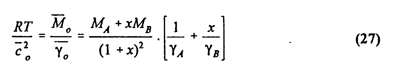
- an acoustic cell can be used to determine the composition of a binary gas mixture from knowledge of the molecular weights of the gasses in a particular gas mixture, their individual specific heat ratios (C p /C v ), and the measurement of the speed of sound.
- C p /C v individual specific heat ratios
- a number of benefits can be derived. These benefits include a determination of the growth rate of thin film material, which can be determined from quantitative information derived from a pair of acoustic cells, or comparable apparatus disposed at the inlet and the outlet of the reactor, and either a knowledge of the reaction chemistry or some independent empirical determination of the absolute efficiency of the acoustic cell measurement.
- a frequency ratio related to the speed of sound ratio ( c / c o ) is measured at the outlet of the reactor by a first acoustic cell while a second acoustic cell measures the inlet composition of the binary gas combination at the inlet; that is, an arriving composition ratio at the reactor inlet.
- a derivation of the reaction fraction ( ⁇ ) can then be calculated from this data alone for each reaction process. The above information provides the reactor's efficiency.
- the growth rate of the thin film can then also be derived.
- information pertaining to the reacted and unreacted products exhausted from the reactor can also be derived using the reaction efficiency, as well as known information pertaining to the mass flow entering the reactor chamber and the dominant chemical reaction in a manner described in greater detail below.
- the above information could also be obtained using a single acoustic cell and by either reducing the temperature, or otherwise turning off the reaction, or by adding a by pass line.
- An advantage of the present invention is that the thin film growth rate onto a substrate, such as, resulting from a chemical vapor deposition reaction, can be calculated easily and quickly using known data and at least one test cell capable of determining the composition of the gas mixture.
- Another advantage of the present invention is that a quantitative analysis of the reaction at the inlet and outlet ports of the reactor is useful in calculating the reaction efficiency and thereby determining information relating to the exhaust product, including the presence of unreacted gasses resulting from an uncompleted reaction.
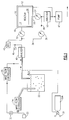
- the CVD reactor 10 includes a housing 12 having an internal cavity or chamber 14 and respective inlet and outlet ports 16, 18.
- a carrier gas bottle 20 is interconnected to a bubbler chamber 22 containing high purity liquid or solid as CVD precursor.
- the bubble chamber 22 is designed to allow carrier gas flow through the precursor while some small amount of the precursor evaporates into the carrier gas.
- the flow of the carrier gas (H 2 according to this embodiment) into the bubble chamber 22 is controlled by a first mass flow controller 24 at a fixed rate and pressure, by known means.
- the precursor is picked up from the liquid and leaves the bubble chamber 22 in gaseous form with the carrier gas obtained from the headspace 23.
- a dilution flow of gas can be carried in a parallel circuit by opening an adjacent valve 33 into a second mass flow controller 25.
- the mass flow controllers or flow meters 24, 25 each include a pair of fine platinum resistance thermometers 28 spaced an equal distance from a small heater element 26, as shown more particularly in FIG. 4.
- the output from the thermometers 28 control an adjacent solenoid-controlled leak valve 35, in a manner commonly known to those in the field.
- some types of precursors can be alternately supplied directly by a gas bottle 20A having an attached pressure regulator 31, as shown.
- some CVD processes utilize direct conversion of the precursor from the liquid state to the vapor state by the careful quantitative metering of the liquid precursor from a source 15, such as using an injector 17 and its subsequent vaporization by a vaporizer 37.
- This vapor is usually carried to the reactor's chamber 10A by a carrier gas, such as hydrogen, oxygen, ammonia (NH 3 ) or argon added to the vaporizer 37 from a supply 29, as monitored by an inline mass flow controller 27.
- a carrier gas such as hydrogen, oxygen, ammonia (NH 3 ) or argon added to the vaporizer 37 from a supply 29, as monitored by an inline mass flow controller 27.
- oxygen (O 2 ) and TEOS are examples of large commercial interest. It is consequently important to know the composition ratio of this mixture as it is carried to the reactor. Again, it is possible to pass all of the mixture through the analyzing means, but in many cases it will be necessary to draw only a representative sample through the analyzer 41 because of flow limitations through the sensor.
- the flow restriction, shown as 43, is used to ensure some portion passes through the acoustic cell. In these cases, a bypass mode of operation will be necessary and can be implemented as described in greater detail below, according to Figs. 5, 6 or 7 as circumstances dictate.
- a first acoustic gas composition cell 40 is positioned adjacent the inlet port 16 external to the reactor 10, while a second acoustic gas composition cell 50 is similarly positioned adjacent the outlet port 18.
- a by-pass line 38 interconnects the first and second acoustic cells 40, 50 bypassing the reactor 10.
- the acoustic cells described by this embodiment are essentially identical, this limitation is not critical to the workings of the present invention. That is, the cells, for example, may vary in size and configuration.
- a back pressure controller 42 having an external pressure gauge 45 is used for maintaining the pressure in the bubbler 22 constant and thereby aiding the stability of precursor pickup by the carrier gas.
- a substrate 30 typically made from silicon or other materials such as GaAs or even various metals or glasses.
- the reactor 10 also includes means (not shown) for uniformly heating the substrate 30 to a reacting temperature. Valves 32, 34, and 36 control the flow of the gas mixture into and out of the reactor cavity 14, and the by-pass line 38, respectively.
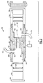
- each of the acoustic cells 40, 50 include a housing 44, preferably made of a metallic material and including a plurality of acoustic cavities 46, 48, and 52, forming a resonator chamber 64.
- a housing 44 preferably made of a metallic material and including a plurality of acoustic cavities 46, 48, and 52, forming a resonator chamber 64.
- First and second diaphragms 54, 56 preferably made from a non-oxidizing and non-reacting metal alloy, such as INCONEL, are installed in the housing 44, using a sealing O-ring 58, which is fit into a groove 60.
- the groove 60 is designed to make a leak tight seal when a diaphragm 54, 56 is sufficiently pressed into it to provide metal-to-metal contact with the front surface of the groove.
- a gas inlet tube 62 is connected to the acoustic cavity 46 via a gas inlet 66, while a corresponding gas outlet tube 74 is connected to the acoustic cavity 52 via gas outlet 76.
- a pair of heater mounting holes 64 are preferably drilled through the housing 44 to maintain the cells 40, 50, Fig. 1, at a given temperature within about 0.1° C or less of the set point as measured by a platinum RTD 77.
- a driving means such as a microphone 68
- a microphone 70 at one end of the cell housing 44 sends an acoustic signal through the gas flowing through the cell housing 44 which is received by a microphone 70 or other receiving means at the other end of the cell housing.
- the microphones 68, 70 are inserted into a chamber 90 provided on either side of the housing 44. End washers 84 retain each microphone 68,70, along with an additional housing 86, (only one side shown), and provide sufficient force to compress the O-ring 58.
- the gas is flowed through the acoustic cell and a driving acoustic signal is transmitted through the gas where the signal is received on the other end.
- the acoustic signal is converted into an electrical signal which is subsequently processed by circuitry (not shown) to detect a resonant frequency resulting from the specific gasses and their composition ratios. Based on this resonant frequency and the resonant frequency of the pure carrier gas, the composition of the binary gas mixture can be calculated. Additional details regarding the operation and features of the acoustic cell 40 are provided in the above cross-referenced application.
- an analysis of the composition of a gas is achieved by the measurement of the speed of sound in a specific gas media using an acoustic gas composition analyzer or cell as shown as reference numerals 40, 50 and briefly described above.
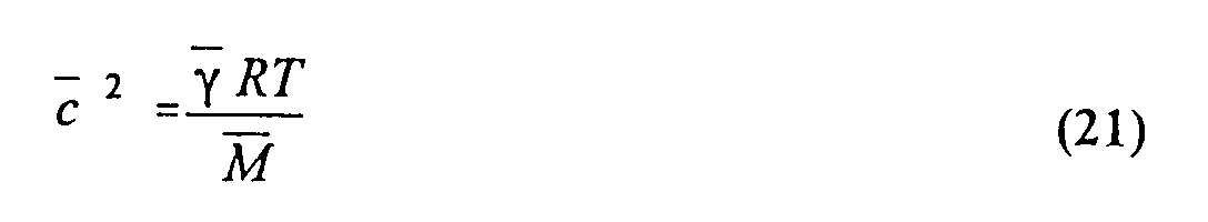
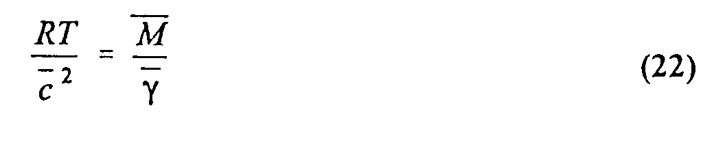
- ⁇ is the average specific heat ratio of the gas mixture
- M is the average molecular weight of the gas mixture
- R is equal to 8311.7 mks units (commonly referred to as the Universal Gas Constant)
- T is the temperature as measured in degrees Kelvin.
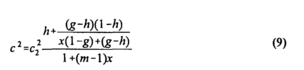
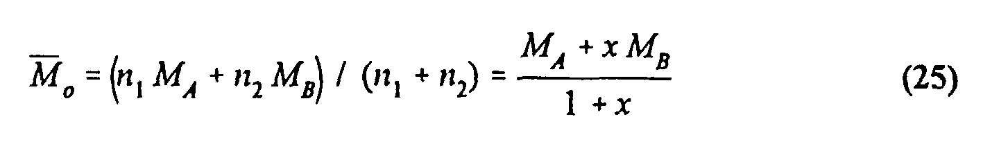
- the average specific heat ratio ⁇ is written as the weighted harmonic average: which can be rewritten as:
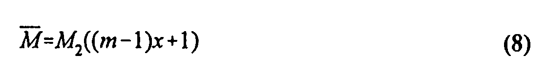
- the average molecular weight, M is the simple weighted average: in which the subscripts 1 and 2 denote the precursor gas and the carrier gas, respectively.
- the mole fraction information for a given binary gas combination is obtained from equations (1) through (4) as follows. For convenience, the following quantities are defined:
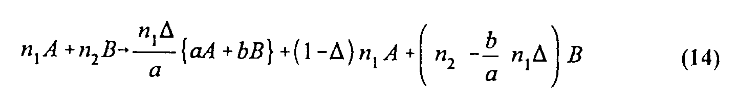
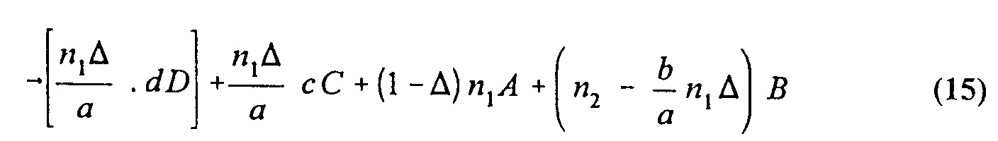
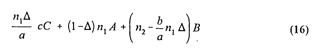
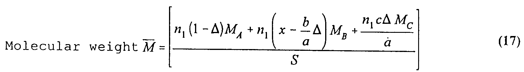
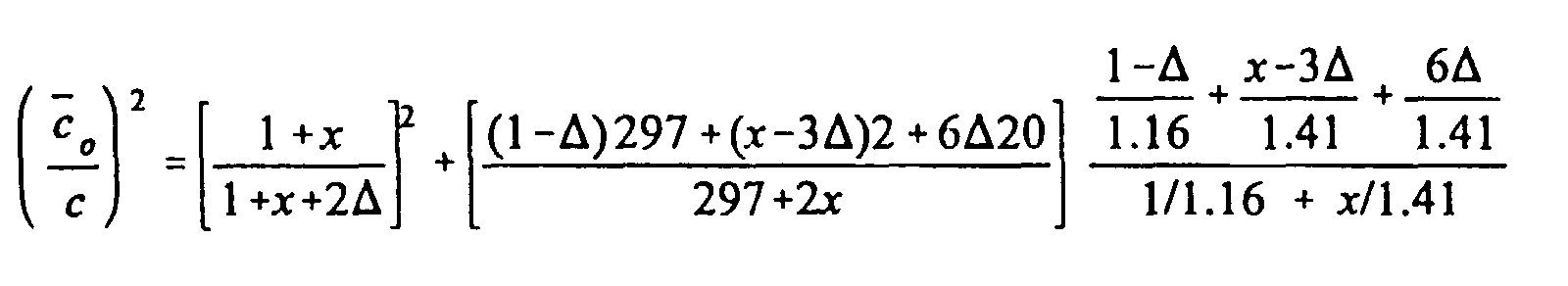
- the gas composition after reaction is therefore: having three components A, B, C in the proportions of n 1 (1- ⁇ ), n 1 ( x - b/a ⁇ ) and n 1 c / a ⁇ , respectively.
- the important gas-related parameters are found as:
- the frequency ratio at the outlet port 16 of the reactor 10 can be determined for a given reaction and inlet mole fraction.
- the decomposition reaction for tungsten hexafluoride and hydrogen having the below reaction equation is herein provided as a working example:
- reaction fraction ( ⁇ ) can be derived using the acoustic cells 40, 50 provided at the inlet and outlet ports 16, 18 of the reactor 10, as follows:
- the inlet composition ( x ) of the binary gas composition is measured and/or controlled by the acoustic cell 40 using the associated mass flow meter 25 in a known manner.
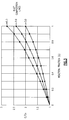
- a graphical representation can be made between the mole fraction (x) and sensor frequency ratio (speed of sound ratio) for a given binary gas composition using an acoustic cell.
- the frequency ratio, c o / c can therefore be determined by measuring the speed of sound in the bypass mode using the bypass line 38, and the speed of sound for the reacted gas combination exhausted through the outlet port 18 of the reactor using valves 32, 34, 36.
- the reacted fraction ( ⁇ ) is then calculated from equation (28) or can be deduced from the graphical representation of Fig. 3.
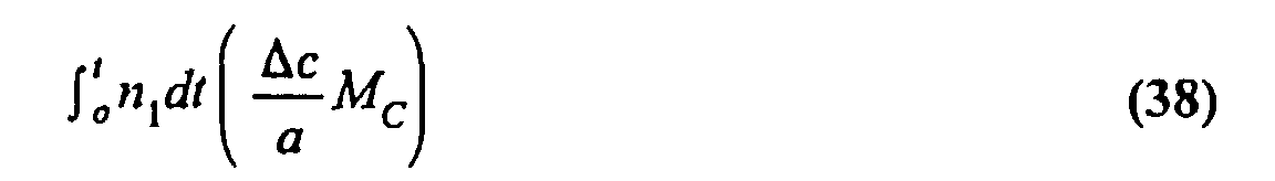
- the reacted fraction ( ⁇ ) provides the reaction efficiency of the CVD reactor 10. Subsequently, the total number of atoms deposited over time in the reactor can be determined by the following equation: where
- the mass flow rate (F) of precursor is derived from and/or measured by the input's mass flow controller 25 and the inlet's measured (or controlled) mole fraction, x , using the acoustic cell 40. in which:
- a volumetric growth rate can be calculated as follows: in which:
- V volumetric growth rate
- the thickness of the thin film, T, deposited on the substrate is therefore equal to the below time-integrated expression: where the limits of the integral are from the start of the deposition, 0, to the end of the deposition process, t.
- W is the measured flow rate of the input precursor (sccm).
- the volatile reaction by-products are calculated from the known decomposition reaction (equation (29)) and the reactor's measured efficiency, E; previously derived using equation (28) and a nomograph such as depicted in Fig. 3, or a calculating machine to determine the reacted fraction from the measureables. This calculation is derived from the chemical reaction and the chemical balance of the particular disassociation process, starting from the mass quantity reacted.
- the chemical breakdown equations form the basis of the calculation of each of the individual reaction components being exhausted. There may be several reaction components created by the reaction, each of which must be calculated according to its particular molecular weight and mass balance considerations.
- n 1 can be deduced (moles/unit time). Then the composition of the exhaust stream is completely known in terms of its constituents and the respective weights of each. Thus, yields the number of gms of species C exhausted in the time interval t . Similar relations hold for the remaining species in the exhaust stream.
- any means of quantitative analysis capable of measuring relative composition with accuracy and stability for the input gasses and the byproducts found in the exhaust may be substituted for the acoustic cells.
- a pair of mass spectrometers specifically tuned for the particular binary gas combination can be substituted for the acoustic cells 40, 50.
- Utilization can be calculated by measuring the gas composition at each mass spectrometer location and subtracting the relative amounts of precursor gas (WF 6 )found at each spectrometer, inlet and outlet. Once the utilization factor has been calculated, the growth rate on the substrate is determined as above.
- one or more infrared spectrometers may be used to measure the precursor density at the inlet and outlet to determine the utilization factor.
- the utilization factor can then be used to determine the growth rate on the substrate in the reactor.
Landscapes
- Physics & Mathematics (AREA)
- Acoustics & Sound (AREA)
- Health & Medical Sciences (AREA)
- Life Sciences & Earth Sciences (AREA)
- Chemical & Material Sciences (AREA)
- Analytical Chemistry (AREA)
- Biochemistry (AREA)
- General Health & Medical Sciences (AREA)
- General Physics & Mathematics (AREA)
- Immunology (AREA)
- Pathology (AREA)
- Chemical Vapour Deposition (AREA)
Abstract
Description
wherein said outlet composition determining means is an acoustic cell capable of measuring relative differences in the speed of sound for gasses passing therethrough, in which the reacted product is derived from the relation:


The important gas-related parameters are found as:


- 10
- reactor
- 10A
- reactor
- 12
- housing
- 14
- cavity
- 15
- liquid precursor source
- 16
- inlet port
- 17
- liquid injector
- 18
- outlet port
- 20
- gas bottle
- 20A
- gas bottle
- 22
- bubble chamber
- 23
- head space
- 24
- mass flow controller
- 25
- mass flow controller
- 26
- thermometers
- 27
- mass flow controller
- 28
- heater element
- 29
- carrier gas source
- 30
- substrate
- 31
- regulator
- 32
- valve
- 33
- valve
- 34
- valve
- 35
- solenoid leak valve
- 36
- valve
- 37
- vaporizer
- 38
- by-pass line
- 40
- acoustic cell
- 41
- analyzer
- 42
- back pressure controller
- 43
- flow restrictions
- 44
- housing
- 45
- pressure gauge
- 46
- acoustic cavity
- 47
- exhaust pump
- 48
- acoustic cavity
- 50
- acoustic cell
- 52
- acoustic cavity
- 54
- diaphragm
- 56
- diaphragm
- 58
- O-ring
- 60
- groove
- 62
- gas-inlet tube
- 64
- gas inlet
- 66
- mounting holes
- 68
- microphone, driver
- 70
- microphone, receiver
- 74
- gas-outlet tube
- 76
- gas outlet
- 77
- platinum RTD
- 84
- end washers
- 86
- housing
- 90
- chamber
Claims (15)
- A method of determining the reaction efficiency of a chemical vapor deposition of a reactive gas reactor, said gas leaving a solid reaction product deposited as a thin film onto a substrate in said reactor, the method comprising the steps of:measuring the gas composition at the outlet of said reactor; anddetermining the reacted fraction of precursor from inlet and outlet gas compositions.
- A method as recited in Claim 1, wherein said gas includes at least one reactive precursor.
- A method as recited in Claim 1, wherein said gas includes a mixture at least one reactive precursor and at least one carrier gas, said method including the additional steps of:controlling the inlet composition of said mixture; anddetermining the reacted fraction from the measured inlet and outlet gas compositions.
- A method as recited in Claim 3, including an acoustic cell at the outlet of said reactor, said method including the additional steps of:determining the speed of sound of the unreacted gas composition at the outlet port;determining the speed of sound of the reacted gas composition at the outlet port;calculating the ratio of the measured speed of sounds of the reacted and unreacted gas compositions; anddetermining the fraction of reacted product using known relationships between the speeds of sound and gas properties, species, and composition.
- A method as recited in Claim 4, wherein a second acoustic cell is positioned adjacent the inlet of said reactor, said method including the steps of:controlling the mass fraction of precursor gas entering said reactor using said second acoustic cell; measuring the speed of sound adjacent the outlet of said reactor of the reacted gas combination using the second acoustic cell;measuring the speed of sound using the second acoustic cell of an unreacted gas combination;calculating the ratio of the speeds measured by the second acoustic cell; andcalculating the fraction of reacted product in the reactor.
- A method as recited in Claim 4, for a binary gas combination of a precursor and a carrier gas, in which the fraction of reacted product is determined using the relationship: for the general chemical reaction equation:
c o is the speed of sound of the unreacted gas mixture;c is the speed of sound of the reacted gas mixture;MA , MB , and MC are the molecular weights of the reaction components;Δ is the fraction of the solid component that has reacted;γ A , γ B , and γ C are the specific heat rates of the reacted components; andx is the mole fraction of the entering precursor in the binary gas mixture. - A method of determining the growth rate of a thin film onto a substrate in a reactor based on a chemical vapor deposition of a reactive gas entering said reactor, the method comprising the steps of:measuring the composition of the reactive gas at an inlet port of the reactor;measuring the composition between the reacted gasses and unreacted gasses at an outlet port of the reactor; anddetermining the reacted fraction of the precursor gas from the measured compositions at the inlet and the outlet of said reactor;determining the mass flow rate of precursor entering said reactor; anddetermining the rate of reacted product deposited onto said substrate.
- A method as recited in Claim 7, wherein said reactive gas includes at least one reactive precursor.
- A method as recited in Claim 7, wherein said gas includes a mixture containing at least one reactive precursor and at least one carrier gas.
- A method as recited in Claim 9, including means for controlling the mass flow rate of precursor into said reactor, said method including the step of controlling the mass flow rate of precursor to a known value.
- A method of calculating the composition of gasses exhausted from a chemical vapor deposition reactor, said method comprising the steps of:measuring the inlet composition of said gas composition;measuring the composition of the gas mixture at the outlet of said reactor;determining the reaction efficiency of the reactor from the measured inlet and outlet gas compositions;determining the unreacted mass fraction of the exhausted gas components;determining the composition of the reacted gas components; andadding the reacted and unreacted gas components to determine the total exhausted gasses.
- A method as recited in Claim 11, wherein the unreacted fraction is calculated from the following relationship:in which:W= input mass flow rate of precursor; andE= reaction efficiency for the chemical reaction
- An apparatus for determining the reaction efficiency of a chemical vapor deposition reactor, said reactor having a defined cavity for retaining at least one substrate onto which is deposited a solid reactionmeans for determining the composition of said gas mixture at the outlet port of the reactor;means for determining the composition of said gas mixture at the inlet port of the reactor;
wherein said outlet composition determining means is an acoustic cell capable of measuring relative differences in the speed of sound for gasses passing therethrough, in which the reacted product is derived from the relation:in which: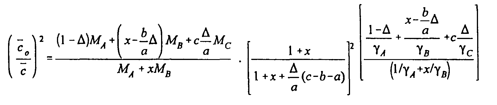 Δ = reacted product;MA , MB , MC =molecular weights of A, B, C;γ A , γ B , γ c =specific heat ratios of A, B, C;x = mole fraction of A; and
 is the measured speed of sound ratio of the gas mixture between a reacted mode and a bypass mode.
 - Apparatus as recited in Claim 13, wherein said inlet determining means is an acoustic cell.
- Apparatus as recited in Claim 14, wherein said inlet determining means includes at least one mass flow meter for controlling the mole fraction of A entering said inlet port.
Applications Claiming Priority (2)
| Application Number | Priority Date | Filing Date | Title |
|---|---|---|---|
| US90241997A | 1997-07-29 | 1997-07-29 | |
| US902419 | 1997-07-29 |
Publications (2)
| Publication Number | Publication Date |
|---|---|
| EP0903577A2 true EP0903577A2 (en) | 1999-03-24 |
| EP0903577A3 EP0903577A3 (en) | 2003-03-05 |
Family
ID=25415841
Family Applications (1)
| Application Number | Title | Priority Date | Filing Date |
|---|---|---|---|
| EP98113036A Withdrawn EP0903577A3 (en) | 1997-07-29 | 1998-07-14 | Acoustic consumption monitor |
Country Status (3)
| Country | Link |
|---|---|
| US (1) | US6482649B1 (en) |
| EP (1) | EP0903577A3 (en) |
| JP (1) | JPH11172453A (en) |
Families Citing this family (6)
| Publication number | Priority date | Publication date | Assignee | Title |
|---|---|---|---|---|
| US6701255B2 (en) * | 2000-04-28 | 2004-03-02 | Ppl Electric Utilities Corp. | Emission monitoring system and method |
| US6772072B2 (en) * | 2002-07-22 | 2004-08-03 | Applied Materials, Inc. | Method and apparatus for monitoring solid precursor delivery |
| US8438933B2 (en) * | 2009-07-15 | 2013-05-14 | Restek Corporation | Flowmeter and manifold therefor |
| US9127361B2 (en) | 2009-12-07 | 2015-09-08 | Mks Instruments, Inc. | Methods of and apparatus for controlling pressure in multiple zones of a process tool |
| JP7281285B2 (en) * | 2019-01-28 | 2023-05-25 | 株式会社堀場エステック | DENSITY CONTROLLER, ZERO POINT ADJUSTMENT METHOD, AND PROGRAM FOR DENSITY CONTROLLER |
| US12596030B2 (en) | 2023-07-12 | 2026-04-07 | General Electric Company | Vibration sensor and methods for deposition monitoring |
Family Cites Families (19)
| Publication number | Priority date | Publication date | Assignee | Title |
|---|---|---|---|---|
| US3449071A (en) * | 1965-09-28 | 1969-06-10 | Lexington Lab Inc | Preparation of alumina crystals from a vapor phase reaction by monitoring the spectral scattering of light |
| BE817066R (en) | 1973-11-29 | 1974-10-16 | REACTION ENCLOSURE FOR THE DEPOSIT OF SEMI-CONCURRING MATERIAL ON HEATED SUPPORT BODIES | |
| US4148931A (en) | 1976-03-08 | 1979-04-10 | Siemens Aktiengesellschaft | Process for depositing elemental silicon semiconductor material from a gas phase |
| JPS55158623A (en) | 1979-05-29 | 1980-12-10 | Hitachi Ltd | Method of controlling semiconductor vapor phase growth |
| US4381894A (en) | 1980-11-06 | 1983-05-03 | Inficon Leybold-Heraeus, Inc. | Deposition monitor and control system |
| US4681640A (en) | 1986-08-06 | 1987-07-21 | The United States Of America As Represented By The Secretary Of The Army | Laser-induced chemical vapor deposition of germanium and doped-germanium films |
| EP0311446A3 (en) * | 1987-10-08 | 1990-11-22 | Mitsubishi Rayon Co., Ltd. | Apparatus for producing compound semiconductor |
| US4857136A (en) | 1988-06-23 | 1989-08-15 | John Zajac | Reactor monitoring system and method |
| US5032435A (en) | 1989-03-27 | 1991-07-16 | The United States Of America As Represented By The United States Department Of Energy | UV absorption control of thin film growth |
| US5060507A (en) * | 1989-06-21 | 1991-10-29 | John Urmson | Method and apparatus for fluid mixture monitoring, constituent analysis, and composition control |
| US5525156A (en) | 1989-11-24 | 1996-06-11 | Research Development Corporation | Apparatus for epitaxially growing a chemical compound crystal |
| JPH04295089A (en) | 1991-03-26 | 1992-10-20 | Kokusai Chodendo Sangyo Gijutsu Kenkyu Center | Apparatus for producing oxide superconducting film |
| US5534066A (en) | 1993-10-29 | 1996-07-09 | International Business Machines Corporation | Fluid delivery apparatus having an infrared feedline sensor |
| US5528924A (en) | 1993-11-29 | 1996-06-25 | Leybold Inficon Inc. | Acoustic tool for analysis of a gaseous substance |
| US5392635A (en) * | 1993-12-30 | 1995-02-28 | At&T Corp. | Acoustic analysis of gas mixtures |
| US5431734A (en) | 1994-04-28 | 1995-07-11 | International Business Machines Corporation | Aluminum oxide low pressure chemical vapor deposition (LPCVD) system-fourier transform infrared (FTIR) source chemical control |
| US5648113A (en) | 1994-09-30 | 1997-07-15 | International Business Machines Corporation | Aluminum oxide LPCVD system |
| JPH08222182A (en) | 1995-02-10 | 1996-08-30 | Hitachi Ltd | Mass spectrometer |
| US5768937A (en) | 1996-11-13 | 1998-06-23 | Leybold Inficon, Inc. | Acoustic sensor for in-line continuous monitoring of gasses |
-
1998
- 1998-07-14 EP EP98113036A patent/EP0903577A3/en not_active Withdrawn
- 1998-07-29 JP JP10214566A patent/JPH11172453A/en active Pending
-
1999
- 1999-09-23 US US09/404,136 patent/US6482649B1/en not_active Expired - Lifetime
Also Published As
| Publication number | Publication date |
|---|---|
| JPH11172453A (en) | 1999-06-29 |
| US6482649B1 (en) | 2002-11-19 |
| EP0903577A3 (en) | 2003-03-05 |
Similar Documents
| Publication | Publication Date | Title |
|---|---|---|
| Smith et al. | Mechanism of SiN x H y Deposition from NH 3‐SiH4 Plasma | |
| Knapas et al. | In situ studies on reaction mechanisms in atomic layer deposition | |
| US7829353B2 (en) | Pulsed mass flow delivery system and method | |
| Funke et al. | Techniques for the measurement of trace moisture in high-purity electronic specialty gases | |
| KR101042133B1 (en) | Method for producing silicon nitride film and silicon oxynitride film by thermochemical vapor deposition | |
| Tsu et al. | Local atomic structure in thin films of silicon nitride and silicon diimide produced by remote plasma-enhanced chemical-vapor deposition | |
| US5288325A (en) | Chemical vapor deposition apparatus | |
| Heil et al. | Reaction mechanisms during plasma-assisted atomic layer deposition of metal oxides: A case study for Al2O3 | |
| CN101466865A (en) | Method for making sedimentation of silicon nitride film and/or silicon nitride oxide film through chemical vapor deposition | |
| WO1999028529A1 (en) | Silicon based films formed from iodosilane precursors and method of making the same | |
| Lucovsky et al. | Atomic structure in SiO2 thin films deposited by remote plasma‐enhanced chemical vapor deposition | |
| EP0903577A2 (en) | Acoustic consumption monitor | |
| CN105228738A (en) | Feedback Control of a Gas Decomposition Reactor Using Raman Spectroscopy | |
| Langlais et al. | Chemical vapour deposition of silicon under reduced pressure in a hot-wall reactor: Equilibrium and kinetics | |
| JP3219184B2 (en) | Organometallic supply and organometallic vapor phase epitaxy | |
| KR20050021446A (en) | Method and apparatus for forming nitrided silicon film | |
| O’Neill et al. | Infrared absorption spectroscopy for monitoring condensible gases in chemical vapor deposition applications | |
| Decosterd et al. | An innovative GC-MS, NMR and ESR combined, gas-phase investigation during chemical vapor deposition of silicon oxynitrides films from tris (dimethylsilyl) amine | |
| Vasilev et al. | Chemical vapour deposition of thin-film dielectrics | |
| Friedman et al. | Electron attachment to Ni (PF3) 4 and Pt (PF3) 4 | |
| Baucom et al. | Monitoring of MOCVD reactants by UV absorption | |
| Zambov et al. | Composition, structure and properties of silicon nitride films grown from dichlorosilane and ammonia at low pressure | |
| ter Heerdt et al. | Surface kinetics in copper CVD | |
| Christe et al. | Fluorine perchlorate. Vibrational spectra, force field, and thermodynamic properties | |
| Kusakabe et al. | Investigation of Precursors Formed by Mixing S i H 2 C l 2 with NH 3 for Chemical Vapor Deposition of Silicon nitride Films |
Legal Events
| Date | Code | Title | Description |
|---|---|---|---|
| PUAI | Public reference made under article 153(3) epc to a published international application that has entered the european phase |
Free format text: ORIGINAL CODE: 0009012 |
|
| AK | Designated contracting states |
Kind code of ref document: A2 Designated state(s): AT BE CH CY DE DK ES FI FR GB GR IE IT LI LU MC NL PT SE |
|
| AX | Request for extension of the european patent |
Free format text: AL;LT;LV;MK;RO;SI |
|
| RIN1 | Information on inventor provided before grant (corrected) |
Inventor name: RUBLOFF, GARY Inventor name: WAJID, ABDUL Inventor name: GOGOL, CARL A., JR. |
|
| RIN1 | Information on inventor provided before grant (corrected) |
Inventor name: RUBLOFF, GARY Inventor name: WAJID, ABDUL Inventor name: GOGOL, CARL A., JR. |
|
| RIC1 | Information provided on ipc code assigned before grant |
Free format text: 7G 01N 29/02 A, 7G 01N 25/00 B, 7G 01N 1/00 B, 7C 23C 16/52 B, 7C 23C 16/44 B, 7G 01N 29/18 B |
|
| PUAL | Search report despatched |
Free format text: ORIGINAL CODE: 0009013 |
|
| AK | Designated contracting states |
Kind code of ref document: A3 Designated state(s): AT BE CH CY DE DK ES FI FR GB GR IE IT LI LU MC NL PT SE Designated state(s): AT BE CH CY DE DK ES FI FR GB GR IE IT LI LU MC NL PT SE |
|
| AX | Request for extension of the european patent |
Extension state: AL LT LV MK RO SI |
|
| AKX | Designation fees paid |
Designated state(s): DE GB |
|
| STAA | Information on the status of an ep patent application or granted ep patent |
Free format text: STATUS: THE APPLICATION IS DEEMED TO BE WITHDRAWN |
|
| 18D | Application deemed to be withdrawn |
Effective date: 20030906 |